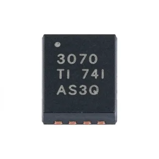
LM2904LVQDGKRQ1 - 5.5V 1MHz Automotive Dual Op Amp | Texas Instruments
MPN: LM2904LVQDGKRQ1 ✓ ActiveLM2904LVQDGKRQ1 Overview
An operational amplifier is an analog integrated circuit that uses high-gain differential amplification to compare an inverting input with a non-inverting input. Within the broader hierarchy, it is a voltage-feedback amplifier, an amplifier IC, and a signal-conditioning semiconductor. The dual configuration allows one device to process two related channels, reducing board area when both channels share the same supply and ground reference.
The LM2904LV-Q1 family targets automotive and industrial low-voltage applications where supply efficiency, cost, and dependable operation are important. The 2.7 V to 5.5 V operating range supports systems powered from regulated 3.3 V and 5 V rails. Its 1 MHz bandwidth makes it suitable for general-purpose amplification, buffering, voltage comparison, filtering, and sensor-interface functions rather than high-speed signal processing.
The dual amplifier architecture is useful in sensor conditioning, current sensing, control loops, line-driver buffers, and automotive body electronics. Each amplifier can be used independently, allowing the two channels to monitor complementary signals or perform separate functions in a compact circuit. Input and output stability, common-mode range, and output-drive capability should be checked against the actual signal levels and load conditions.
The principal design trade-off is that this is a general-purpose, low-voltage amplifier rather than a precision or high-speed device. Its 3 mV offset specification is appropriate for many sensing and control paths, but systems requiring tighter offset accuracy need to evaluate the bias current, input voltage range, noise, and application error budget.
This page combines the manufacturer specifications, package information, application guidance, comparison parameters, and practical drop-in selection notes for engineers evaluating the LM2904LVQDGKRQ1.
Drop-in alternatives for LM2904LVQDGKRQ1 — same package, pin-to-pin compatible. Different-package parts requiring PCB rework are excluded.
LM2904LVQDRQ1
✅ Drop-InContact for price
View Datasheet →LM2904LVQDGKRQ1
✅ Drop-InContact for price
View Datasheet →LM2904LVQDGKRQ1-Q1
✅ Drop-In ⚠️ Specs Unverified📋 Reference alternative (not in catalog)
LM2904QDGKRQ1
✅ Drop-In ⚠️ Specs Unverified📋 Reference alternative (not in catalog)
LM2902LVQDGKRQ1
✅ Drop-In ⚠️ Specs Unverified📋 Reference alternative (not in catalog)
LM2904LVQDGKRQ1 Maximum Ratings & Electrical Characteristics
| Product Type | Dual operational amplifier |
| Number of Amplifier Circuits | 2 circuits |
| Supply Voltage Range | 2.7 V to 5.5 V |
| Maximum Supply Voltage | 5.5 V |
| Gain-Bandwidth Product | 1 MHz |
| Input Offset Voltage | 3 mV |
| Automotive Qualification | AEC-Q100 automotive-grade device |
| Package | 8-VSSOP |
| Mounting Type | Surface mount |
| Standard Product | General-purpose operational amplifier |
LM2904LVQDGKRQ1 8-vssop Pin Configuration Guide
Pin configuration for LM2904LVQDGKRQ1 (8-vssop package). This analog component features input, output, and power supply pins. Refer to the manufacturer datasheet for offset null, compensation, and enable pin configurations. Ideal for signal conditioning and amplifier circuits.

No detailed pinout data available for LM2904LVQDGKRQ1.
Refer to the datasheet for full pin configuration.
Typical Applications
LM2904LVQDGKRQ1 is suitable for 6 applications: Automotive Sensor Signal Conditioning, 3.3V Control-Loop Amplification, Automotive Actuator Drive Interface, Battery-Powered Monitoring Circuit, Active Filtering and Buffering, Low-Voltage Industrial Interface.
Automotive Sensor Signal Conditioning
The LM2904LVQDGKRQ1 fits low-voltage automotive sensor conditioning because it accepts a 2.7 V to 5.5 V supply and provides two amplifier channels for related inputs. Its 1 MHz gain-bandwidth product is adequate for buffering and modest-gain stages in 3.3 V or 5 V sensor interfaces. The 3 mV input offset specification must be included in the system error budget, while the dual layout helps reduce board area compared with two separate single amplifiers.
Recommended
3.3V Control-Loop Amplification
In a 3.3 V control system, the LM2904LVQDGKRQ1 can amplify error signals, support active filtering, or buffer a feedback node. Its 2.7 V lower supply limit provides operating margin below a nominal 3.3 V rail, while the 1 MHz bandwidth supports general-purpose control-loop functions. The designer should verify the input common-mode range, output swing, stability with the selected feedback network, and the offset contribution of 3 mV.
Recommended
Automotive Actuator Drive Interface
The dual amplifier can serve as the input and feedback stage for a low-voltage automotive actuator interface. Placing the device between a sensor or command signal and a downstream driver stage can improve drive capability and isolate the source from the load. The 5.5 V maximum supply keeps the device aligned with low-voltage automotive rails, while the 3 mV offset and 1 MHz bandwidth define the main error and dynamic-performance constraints.
Recommended
Battery-Powered Monitoring Circuit
For a battery-powered monitor, the LM2904LVQDGKRQ1 can amplify a low-level sensor signal near a regulated 3.3 V rail. Its low-voltage supply operation reduces the need for a high-voltage amplifier in portable or energy-limited systems, and two channels can monitor two measurements with a shared supply. The application must account for battery variation, common-mode input limits, output headroom, and the offset error introduced by the 3 mV specification.
Recommended
Active Filtering and Buffering
The LM2904LVQDGKRQ1 is suitable for first-order active filters, unity-gain buffers, and general analog conditioning when the required bandwidth is near the 1 MHz gain-bandwidth class. The dual package allows two filters or buffers to share one package and supply node. Design the feedback network around the actual load and source impedance, and confirm that the operating point keeps both input and output signals within the device's voltage limits.
Recommended
Low-Voltage Industrial Interface
The LM2904LVQDGKRQ1 can support general-purpose industrial interfaces running from regulated 3.3 V or 5 V supplies. It can buffer transducer outputs, compare control signals, or provide gain before a communications or power-control stage. The automotive-qualified family status is useful when ruggedized sourcing is preferred, but the designer should still verify the exact temperature range, input/output limits, and board-level noise behavior.
Recommended
Recommended Products Summary
Engineering reference data for LM2904LVQDGKRQ1 — comparison, design guidance, and compliance information.
Selection Guide
Comparison with Alternatives
| Parameter | This Product | LM2904LVQDRQ1 | LM2904LVQDGKRQ1 | LM2904LVQDGKRQ1-Q1 | LM2904QDGKRQ1 | LM2902LVQDGKRQ1 |
|---|---|---|---|---|---|---|
| Brand | Texas Instruments | Texas Instruments | Texas Instruments | Texas Instruments | Texas Instruments | Texas Instruments |
| Package | 8-VSSOP | 8-VSSOP | 8-VSSOP | 8-VSSOP | 8-VSSOP | 8-VSSOP |
| Amplifier Configuration | Dual, 2 circuits | Dual, 2 circuits | Dual, 2 circuits | Dual, 2 circuits | Dual, 2 circuits | Quad, 4 circuits |
| Automotive Grade | Yes | Yes | Yes | Yes | Yes | Yes |
Key Differentiators
- Low-voltage operation (vs LM2904QDGKRQ1)
- Dual-channel integration (vs LM2902LVQDGKRQ1)
- Automotive-oriented family positioning (vs LM2904LVQDRQ1)
Design Notes
Place the supply bypass capacitor as close as practical to the V+ and ground pins, and use a short, low-inductance return path. Keep input, feedback, and output routing compact because parasitic capacitance in the feedback network can alter stability. The exact decoupling value and layout should follow the manufacturer recommendations for the LM290xLV-Q1 family.
Do not assume that a 5.5 V maximum supply allows a 5.5 V signal at every pin. Check the input common-mode range and output swing before using the amplifier near either supply rail. For low-voltage designs, calculate the offset contribution from the 3 mV input-offset specification and confirm that the feedback network remains stable with the selected source and load impedances.
Estimated: the device power dissipation is approximately the supply voltage multiplied by total supply current plus output-stage load dissipation. The input values for an exact calculation are 5.5 V maximum supply and the application-specific supply current. Use the manufacturer thermal data and the actual board copper area for junction-temperature verification.
Compliance Information
Texas Instruments identifies the LM2904LV-Q1 family as automotive-grade. Specific RoHS, REACH, lead-free, halogen-free, and conflict-minerals statuses require confirmation for the exact ordering code.