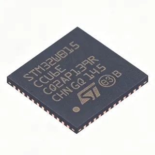
MFRC52202HN1,157 - 13.56MHz MIFARE NFC Reader IC | NXP
MPN: MFRC52202HN1,157 ✗ End of Life| Qty | Unit Price | Extended |
|---|---|---|
| 1 | $6.9 | $6.90 |
| 10 | $6.45 | $64.50 |
| 100 | $5.8 | $580.00 |
| 500 | $5.2 | $2,600.00 |
| 1,000 | $4.9 | $4,900.00 |
MFRC52202HN1,157 Overview
A 13.56 MHz NFC reader front-end is a radio-frequency integrated circuit that generates the carrier field, modulates and demodulates data, and handles the ISO/IEC 14443 Type A protocol framing needed to communicate with contactless cards, MIFARE classics, and NTAG tags. It sits inside the NFC/HF radio hierarchy: contactless reader IC -> HF RFID transceiver -> RF transceiver -> mixed-signal semiconductor, bridging the analog RF domain and the digital host system.
Key features include the 13.56 MHz carrier for contactless communication, support for ISO/IEC 14443 A, MIFARE and NTAG card families, flexible host interfaces (SPI, I2C, and serial UART selected via pin strap options), and a compact 32-VFQFN exposed-pad package that aids thermal dissipation and RF grounding. An integrated analog front-end with low-power mode makes it suitable for battery-conscious reader designs.
Technically, the device integrates the complete analog front end: a 13.56 MHz oscillator interface for an external crystal, Tx drivers feeding an external antenna matching network, Rx gain stages for load-modulated tag responses, and a digital engine handling framing, CRC, and the parallel-host or serial-host register interface. Version 2.0 silicon refinements improve RF timing robustness compared with the original MFRC522 v1.0.
Typical applications include access-control card readers, embedded NFC/RFID development platforms (notably Arduino RC522 shields), smart labeling and tagging stations, and point-of-interaction read stations for MIFARE and NTAG credentials. The 2.5 V to 3.3 V supply range pairs naturally with 3.3 V microcontrollers.
Design consideration: this part is Not Recommended for New Designs; NXP directs new designs to the CLRC663 plus family, so budget for migration in long-lived products. RF performance depends heavily on the antenna matching network and PCB ground plane.
This page synthesizes distributor pricing, availability, drop-in family alternatives, and practical migration guidance not consolidated in the manufacturer datasheet.
Drop-in alternatives for MFRC52202HN1,157 — same package, pin-to-pin compatible. Different-package parts requiring PCB rework are excluded.
Quick Comparison Tool — Select alternative parts for side-by-side comparison:
MFRC52201HN1,157
✅ Drop-In ⚠️ 参数待验证📋 Reference alternative (not in catalog)
MFRC52301HN1,157
✅ Drop-In ⚠️ 参数待验证📋 Reference alternative (not in catalog)
PN5120A1HN,157
✅ Drop-In ⚠️ 参数待验证📋 Reference alternative (not in catalog)
MFRC52202HN1,157 Specifications
| Function | Contactless reader/writer front-end IC (Read/Write) |
| Operating Frequency | 13.56 MHz |
| Supported Standards | ISO/IEC 14443 A, MIFARE, NTAG |
| Host Interfaces | SPI, I2C, UART |
| Supply Voltage Range | 2.5 V to 3.3 V (per distributor listing) |
| Interface Logic Level | 2.5 V to 3.3 V |
| Package | 32-VFQFN (HVQFN-32) Exposed Pad |
| Silicon Version | Version 2.0 |
| Low Power Mode | Yes |
| Mounting Type | Surface Mount |
| Packaging | Tray |
| Lifecycle Status | Not Recommended for New Designs (successor: CLRC663 plus) |
| Category | NFC/RFID Tags & Transponders / RFID Reader ICs |
MFRC52202HN1,157 32-vfqfn (hvqfn-32) exposed pad Pin Configuration Guide
Pin configuration for MFRC52202HN1,157 (32-vfqfn (hvqfn-32) exposed pad package). Pin numbering, functions, and connection diagrams are defined in the manufacturer datasheet. Refer to it for the exact footprint and soldering guidelines.

No detailed pinout data available for MFRC52202HN1,157.
Refer to the datasheet for full pin configuration.
Typical Applications
MFRC52202HN1,157 is suitable for 6 applications: Access Control Card Readers, Embedded Development and Prototyping (RC522 Modules), Smart Labeling and Inventory Tagging Stations, Point-of-Interaction and Payment-Adjacent Terminals, IoT Devices and Smart Home NFC Nodes, Public Transport and Ticketing Read Points.
Access Control Card Readers
The MFRC52202HN1,157 fits door and gate access-control readers that credential with MIFARE Classic or NTAG cards at 13.56 MHz. Its ISO/IEC 14443 A front-end handles the full reader-to-card transaction, while the SPI/I2C/UART host interface connects directly to a 3.3 V microcontroller managing the relay or Wiegand output. The 2.5 V to 3.3 V supply range simplifies integration in reader head units powered from 3.3 V rails. Because antenna performance is set by the external matching network, a typical 50 to 60 mm diameter loop antenna tuned to 13.56 MHz delivers read distances in the several-centimeter class appropriate for deliberate card presentation. Note the NRND status: long-lifetime building infrastructure should plan CLRC663 plus migration while using the MFRC522 for footprint-proven continuity in existing product lines.
Recommended
Embedded Development and Prototyping (RC522 Modules)
The MFRC52202HN1,157 is the silicon inside the ubiquitous RC522 NFC/RFID modules used with Arduino, ESP32 and STM32 platforms. The bare IC's SPI interface runs at logic levels of 2.5 V to 3.3 V, so 3.3 V hosts connect directly while 5 V hosts need level shifting. For prototyping MIFARE and NTAG reading, the Version 2.0 front-end provides the same 13.56 MHz carrier and ISO 14443 A framing as production parts, letting firmware move directly from breadboard to product. Developers should remember the exposed-pad HVQFN-32 is hand-soldering-challenging, which is why module form factors dominate hobby use. Given NRND status, prototypes for commercial products should be validated against the CLRC663 plus early, using the MFRC522 for algorithm development since the MIFARE/NTAG protocol handling carries over conceptually.
Recommended
Smart Labeling and Inventory Tagging Stations
Desktop tag programmers and inventory stations write NTAG and MIFARE Ultralight tags using the MFRC52202HN1,157 as the read/write engine. The 13.56 MHz front-end supports the anti-collision framing needed to reliably address a single tag presented on the antenna, and the UART interface allows a simple host such as a label printer controller to issue write commands. Low-power mode reduces consumption when the station idles between scans, useful in battery-backed portable inventory terminals. The exposed-pad QFN-32 keeps the RF section compact enough for handheld enclosures. For stations requiring longer read range than the MFRC522's proximity-class performance, NXP's higher-power reader ICs are the upgrade path; for standard tag programming at 0 to 5 cm, this part is cost-effective, with the caveat that new station designs should adopt the recommended CLRC663 plus successor.
Recommended
Point-of-Interaction and Payment-Adjacent Terminals
Kiosks and loyalty terminals that read MIFARE-based transit cards or NFC loyalty tags can integrate the MFRC52202HN1,157 as the 13.56 MHz proximity front-end. Its ISO/IEC 14443 A support covers the card-side protocols of MIFARE ecosystems, and the selectable SPI/I2C/UART interface eases integration with payment terminal main boards, which commonly expose I2C or SPI peripherals. The 2.5 V to 3.3 V operation matches typical terminal logic rails, and the HVQFN exposed pad conducts RF ground to the PCB, containing emissions within regulatory EMC limits when the datasheet EMC filter network is used. Strictly for EMV contactless payment, higher-certified NXP reader ICs are required; the MFRC522 suits non-payment card reading, badge scanning and tagging functions, with CLRC663 plus as the forward-looking choice given NRND status.
Recommended
IoT Devices and Smart Home NFC Nodes
Battery-conscious IoT nodes use the MFRC52202HN1,157's low-power mode to poll for NTAG tap events without draining the supply. A typical smart-home setup pairs the reader IC with a Wi-Fi or BLE MCU: the reader wakes on card field detection, the MCU then reads the NTAG UID or NDEF payload over SPI at 3.3 V logic and forwards it to the cloud. The 32-VFQFN exposed-pad package occupies minimal board area in wall sensors and smart locks. Energy budgeting should account for transmit-phase current during field generation, which dominates the duty cycle; keeping the antenna small for tap-to-unlock use cases limits peak current. Because this silicon is NRND, battery-powered products with multi-year service expectations should design against the active CLRC663 plus, reserving the MFRC522 for short-run or legacy-compatible builds.
Recommended
Public Transport and Ticketing Read Points
Transit validators and fare-gate read points built on MIFARE card ecosystems historically used MFRC522-class front-ends for the 13.56 MHz ISO/IEC 14443 A air interface. The MFRC52202HN1,157's Version 2.0 silicon improves RF timing margins relevant to fast card presentation at gates, where transactions must complete in a few hundred milliseconds. The differential Tx1/Tx2 drive pairs with a gate-sized antenna through the datasheet matching network, and the IRQ pin lets the host MCU sleep until a card enters the field, reducing validator idle power. For fleet-wide deployments, however, the NRND status is decisive: fare infrastructure lives 10 to 15 years, so NXP's recommended CLRC663 plus, with its broader protocol support (including FeliCa and ISO 15693 for multimodal ticketing), is the correct platform for future validators.
Recommended
Recommended Products Summary
Engineering reference data for MFRC52202HN1,157 — comparison, design guidance, and compliance information.
Selection Guide
Comparison with Alternatives
| Parameter | This Product | MFRC52201HN1,157 | MFRC52301HN1,157 | PN5120A1HN,157 |
|---|---|---|---|---|
| Package | 32-VFQFN (HVQFN) Exposed Pad | 32-VFQFN (HVQFN) Exposed Pad - same | 32-VFQFN (HVQFN) Exposed Pad - same | 32-VFQFN (HVQFN) Exposed Pad - same |
| Brand | NXP Semiconductors | NXP Semiconductors | NXP Semiconductors | NXP Semiconductors |
| Operating Frequency | 13.56 MHz | 13.56 MHz | 13.56 MHz | 13.56 MHz |
| Supported Protocols | ISO/IEC 14443 A, MIFARE, NTAG | ISO/IEC 14443 A, MIFARE, NTAG | ISO/IEC 14443 A + MIFARE (broader family coverage) | ISO/IEC 14443 A, MIFARE (NTAG support per family revision) |
| Host Interfaces | SPI, I2C, UART | SPI, I2C, UART | SPI, I2C, UART | SPI, I2C, UART |
Key Differentiators
- Version 2.0 silicon of the proven MFRC522 family (vs MFRC52201HN1,157)
- MIFARE and NTAG protocol coverage at standard performance tier (vs PN5120A1HN,157)
- Direct ecosystem compatibility (RC522 module libraries) (vs CLRC663 plus)
Design Notes
Solder the exposed pad of the HVQFN-32 to a grounded copper pour with an array of thermal vias; the pad is the primary RF and thermal ground for the MFRC52202HN1,157. Place the 13.56 MHz crystal within 5 mm of OSCIN/OSCOUT with short traces, and keep the antenna matching network (series capacitors on Tx1/Tx2 plus the antenna tank) symmetrical and close to the device. Decouple TVDD, DVDD and AVSS individually with 100 nF ceramics placed within a few millimeters of each pin. Follow NXP's antenna design application note for the matching component values.
The MFRC52202HN1,157 operates from 2.5 V to 3.3 V; do not connect it to a 5 V rail or 5 V logic without level shifting, a common failure mode in Arduino-based designs. Estimated: transmit-phase current during field generation is the dominant load (datasheet-table value marked [DATA_NEEDED: typical supply current]); budget the local 3.3 V regulator for the datasheet Tx peak figure plus margin, and use low-ESR bulk capacitance near TVDD to prevent field-collapse during RF bursts.
The part is NRND: NXP explicitly directs new designs to the CLRC663 plus, so do not start multi-year-lifetime products on this IC without a migration plan. Additionally, the SPI/I2C/UART selection is pin-strapped, so mislabeled strap resistors are a frequent bring-up failure; verify the interface pins per the datasheet table before debugging communication. Finally, remember protocol support is limited to ISO/IEC 14443 A/MIFARE/NTAG - Type B or FeliCa requirements cannot be met by firmware changes.
Compliance Information
The ,157 ordering suffix in NXP convention denotes lead-free/RoHS-compliant packaging, but explicit compliance statements were not present in the provided verified data; verify on the NXP product page before publication-critical use.