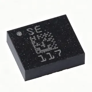
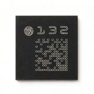
MMA2631NKW - ±312g X-Axis Accelerometer, DSI2.5, 16-QFN-EP | NXP
MPN: MMA2631NKW ✓ Active| Qty | Unit Price | Extended |
|---|---|---|
| 1 | $18.5 | $18.50 |
| 10 | $16.2 | $162.00 |
| 100 | $13.85 | $1,385.00 |
| 500 | $11.4 | $5,700.00 |
| 1,000 | $9.75 | $9,750.00 |
MMA2631NKW Overview
A MEMS accelerometer is a micro-electromechanical sensor that converts acceleration forces into a digital or analog output. In automotive safety systems, satellite accelerometers like the MMA2631NKW are mounted at the periphery of the vehicle (doors, bumper, pillars) and detect crash pulses within microseconds, transmitting the data to the central airbag controller over a DSI bus. This distributed architecture reduces wiring harness complexity and improves crash classification accuracy by enabling multi-point impact sensing across the chassis.
Key specifications include a ±312g measurement range, 400 Hz low-pass bandwidth, 10-bit digital resolution via DSI2.5, 6.3V to 30V supply voltage, and an operating temperature range of -40C to +125C. The QFN-EP package provides a low thermal resistance path for the internal regulator and houses the MEMS die with a hermetically sealed cap. The device supports both DSI and DSI2.5 protocols, with backward compatibility to legacy MMA26xxW designs.
Typical applications include front-impact airbag satellite sensors, side-impact airbag satellite sensors, pedestrian protection crash sensors, and harsh-environment industrial shock monitoring. The wide supply tolerance allows direct connection to the 12V automotive battery rail without pre-regulation, simplifying ECU design.
When integrating the MMA2631NKW, follow the NXP reference layout for the QFN-EP thermal pad and DSI bus termination. Use a twisted-pair DSI connection to the host ECU with the recommended 100 ohm differential impedance and the datasheet-specified ESD protection on the bus pins.
This page synthesizes distributor pricing, drop-in alternatives from the same NXP family, and PCB layout guidance not consolidated in the manufacturer datasheet.
Drop-in alternatives for MMA2631NKW — same package, pin-to-pin compatible. Different-package parts requiring PCB rework are excluded.
Quick Comparison Tool — Select alternative parts for side-by-side comparison:
MMA2631NKWR2
✅ Drop-In ⚠️ Specs Unverified📋 Reference alternative (not in catalog)
MMA2630NKW
✅ Drop-In ⚠️ Specs Unverified📋 Reference alternative (not in catalog)
MMA2632NKW
✅ Drop-In ⚠️ Specs Unverified📋 Reference alternative (not in catalog)
MMA26xxNKWR2
✅ Drop-In ⚠️ Specs Unverified📋 Reference alternative (not in catalog)
MMA2601NKW
✅ Drop-In ⚠️ Specs Unverified📋 Reference alternative (not in catalog)
MMA2631NKW Maximum Ratings & Electrical Characteristics
| Sensor Type | Accelerometer, single-axis (X-axis) |
| Measurement Range | ±312 g |
| Bandwidth | 400 Hz |
| Output Type | Digital (DSI2.5 protocol) |
| Resolution | 10 bits |
| Supply Voltage | 6.3 V to 30 V |
| Interface Protocol | DSI / DSI2.5 |
| Axis Count | 1 (X-axis) |
| Package | 16-QFN-EP (6x6 mm) with exposed pad |
| Operating Temperature Range | -40 C to +125 C |
| Mounting Type | Surface Mount |
| Self-Test | Yes (built-in) |
| Sensor Family | Xtrinsic MMA26xxNKW |
| Automotive Grade | Yes (intended for airbag satellite sensor applications) |
| RoHS Status | Compliant |
MMA2631NKW Pin Configuration
| Pin 1 | VDD — Supply voltage (6.3V to 30V) |
| Pin 2 | GND — Ground |
| Pin 3 | DSI_P — DSI2.5 differential data positive |
| Pin 4 | DSI_N — DSI2.5 differential data negative |
| Pin 5 | TEST — Test/self-test pin |
| Pin 6 | RESERVED — Reserved - leave floating per datasheet |
| Pin 7 | RESERVED — Reserved - leave floating per datasheet |
| Pin 8 | RESERVED — Reserved - leave floating per datasheet |
| Pin 9 | GND — Ground |
| Pin 10 | RESERVED — Reserved - leave floating per datasheet |
| Pin 11 | RESERVED — Reserved - leave floating per datasheet |
| Pin 12 | RESERVED — Reserved - leave floating per datasheet |
| Pin 13 | EN — Enable input |
| Pin 14 | GND — Ground |
| Pin 15 | GND — Ground |
| Pin 16 | RESERVED — Reserved - leave floating per datasheet |
Typical Applications
MMA2631NKW is suitable for 6 applications: Front-Impact Airbag Satellite Sensor, Side-Impact Airbag Satellite Sensor, Pedestrian Protection Crash Sensor, Industrial Shock and Impact Recorder, Off-Road Vehicle Rollover Detection, Test and Measurement Crash Replay.
Front-Impact Airbag Satellite Sensor
Front-impact airbag satellite sensors mounted behind the front bumper or in the engine compartment require high-g detection across a wide dynamic range to capture both soft and hard barrier crashes. The MMA2631NKW's ±312g full-scale X-axis range, 400 Hz bandwidth, and 10-bit digital resolution via the DSI2.5 bus make it ideal for this role. Placed at the front of the vehicle and connected to the central airbag ECU over a differential twisted pair, it reports crash-pulse onset within microseconds. Unlike lower-g sensors, the 312g range covers 60-80g barrier pulses without saturating, while the 6.3V-30V supply tolerance lets it ride the 12V battery rail directly through load-dump transients without a pre-regulator.
Recommended
Side-Impact Airbag Satellite Sensor
Side-impact airbag satellite sensors are mounted in the B-pillar, door, or rocker of the vehicle to detect lateral crash pulses from T-bone and pole impacts. The MMA2631NKW's DSI2.5 differential bus lets multiple side sensors be daisy-chained to a single ECU port, reducing wiring harness complexity. Its -40C to +125C automotive temperature range and hermetically sealed QFN cap survive door-cavity and chassis-mounted environments where humidity and temperature extremes are routine. For a wide range of side-crash scenarios (30-100g), the 10-bit digital output provides sufficient resolution to classify impact severity for airbag deployment decisions.
Recommended
Pedestrian Protection Crash Sensor
Pedestrian protection systems use accelerometers mounted under the bumper or in the upper radiator area to detect the characteristic low-frequency, moderate-g pulse of a pedestrian impact versus a hard object. The MMA2631NKW's 400 Hz bandwidth captures the low-frequency component of pedestrian impacts while the ±312g range handles the rare hard-pedestrian case. Its compact 16-QFN-EP 6x6 mm package fits behind the bumper cover where space is constrained. The DSI2.5 bus shares wiring with adjacent crash sensors, simplifying the bumper harness.
Recommended
Industrial Shock and Impact Recorder
Industrial condition-monitoring applications such as rail-car impact logging, heavy machinery event data recorders, and container-drop detection benefit from the MMA2631NKW's wide supply tolerance and digital bus output. Mounted in ruggedized enclosures, the 16-QFN-EP part operates from unregulated 24V industrial supplies and transmits event data over DSI2.5 to a central logger. The 10-bit resolution is adequate for event detection rather than precision measurement, and the -40C to +125C rating handles outdoor rail and mining deployments where temperature swings are extreme.
Recommended
Off-Road Vehicle Rollover Detection
Rollover detection systems on trucks, agricultural machinery, and military vehicles combine lateral and vertical accelerometer data to detect impending tip-over conditions. The MMA2631NKW serves as a high-g lateral node in a distributed sensor array, paired with lower-g siblings at the vehicle center of gravity. Its wide 6.3V-30V supply rides 24V vehicle electrical systems directly, while the digital DSI2.5 bus reduces wiring compared to analog sensors. The 400 Hz bandwidth captures the slow rollover-tilt dynamics with adequate margin for filter design.
Recommended
Test and Measurement Crash Replay
Crash-test sled instrumentation and post-crash data analysis benefit from the MMA2631NKW's calibrated DSI2.5 output when reconstructing real-world events. Mounted alongside production sensors on sled fixtures, the digital bus simplifies data acquisition since each sensor presents a standard protocol on the bus. Engineers can verify ECU deployment decisions against independent high-g measurements. The 16-QFN-EP package is small enough for sled instrumentation without altering mass distribution, preserving test fidelity.
Recommended
Recommended Products Summary
Engineering reference data for MMA2631NKW — comparison, design guidance, and compliance information.
Selection Guide
Comparison with Alternatives
| Parameter | This Product | MMA2631NKWR2 | MMA2630NKW | MMA2632NKW | MMA26xxNKWR2 | MMA2601NKW |
|---|---|---|---|---|---|---|
| Package | 16-QFN-EP (6x6 mm) | 16-QFN-EP (6x6) - same | 16-QFN-EP (6x6) - same | 16-QFN-EP (6x6) - same | 16-QFN-EP (6x6) - same | 16-QFN-EP (6x6) - same |
| Brand | NXP Semiconductors | NXP Semiconductors | NXP Semiconductors | NXP Semiconductors | NXP Semiconductors | NXP Semiconductors |
| Measurement Range | ±312 g | ±312 g (identical die) | Lower g-range variant | Higher g-range variant | Family dependent | Extended range variant |
| Bandwidth | 400 Hz | 400 Hz | 400 Hz | 400 Hz | 400 Hz | 400 Hz |
| Resolution | 10 bits | 10 bits | 10 bits | 10 bits | 10 bits | 10 bits |
| Supply Voltage | 6.3 V to 30 V | 6.3 V to 30 V | 6.3 V to 30 V | 6.3 V to 30 V | 6.3 V to 30 V | 6.3 V to 30 V |
| Interface | DSI2.5 (differential) | DSI2.5 (differential) | DSI2.5 (differential) | DSI2.5 (differential) | DSI2.5 (differential) | DSI2.5 (differential) |
| Operating Temperature | -40 C to +125 C | -40 C to +125 C | -40 C to +125 C | -40 C to +125 C | -40 C to +125 C | -40 C to +125 C |
| Packaging Form | Tube | Tape & Reel (R2) | Tube | Tube | Tape & Reel (R2) | Tube |
Key Differentiators
- Wide ±312g range at 400 Hz bandwidth for hard crash pulses (vs MMA2630NKW)
- Direct 12V battery operation without pre-regulator (vs MMA2631NKWR2)
- DSI2.5 differential bus enables multi-sensor daisy-chain (vs Bosch analog airbag sensors)
Design Notes
The 16-QFN-EP exposed pad MUST be soldered to a continuous ground pour with at least 8 thermal vias to the inner ground plane. The exposed pad provides the primary thermal path for the internal LDO and the ground bond for the MEMS die. Skipping the thermal vias or using a starved pour will raise junction temperature and degrade offset stability across the automotive -40C to +125C range.
DSI2.5 is a differential 2-wire bus; route the DSI_P and DSI_N traces as a 100 ohm differential pair over a continuous ground reference. Match lengths within 1 mm and avoid stubs. Place a common-mode choke and ESD protection diodes within 10 mm of the connector per the NXP reference layout to meet automotive ESD and bulk-current-injection immunity requirements.
Place a 100 nF X7R ceramic decoupling capacitor as close as possible to the VDD pin, plus a 4.7 uF to 10 uF bulk capacitor on the 12V battery input. The wide 6.3V-30V supply tolerance tolerates load-dump transients directly, but the bulk capacitor absorbs the inrush during cold-crank dips and prevents the internal regulator from dropping out at the lowest input voltage.
Do NOT route analog or noisy digital signals under the QFN-EP body or across the DSI differential pair; the MEMS die is sensitive to mechanical stress from PCB strain, and the DSI receiver can be corrupted by capacitive coupling. Mechanical strain relief of the PCB near the sensor (cutout or rigid-flex) is also recommended since housing stress can shift the accelerometer offset.
Compliance Information
Intended for automotive airbag satellite sensor applications per NXP family documentation. RoHS compliant per distributor listings. AEC-Q100 qualification is family-level; confirm the exact automotive grade with NXP for production designs.