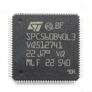
STM32L073VZT6 - 192KB Flash, 32MHz ARM Cortex-M0+ MCU | STMicroelectronics
MPN: STM32L073VZT6 ✓ Active| Qty | Unit Price | Extended |
|---|---|---|
| 1 | $6.5 | $6.50 |
| 10 | $5.85 | $58.50 |
| 100 | $5.2 | $520.00 |
| 500 | $4.68 | $2,340.00 |
| 1,000 | $4.16 | $4,160.00 |
STM32L073VZT6 Overview
What is an ARM Cortex-M0+ microcontroller? It is a 32-bit processor core designed for low-power and cost-sensitive embedded applications. The Cortex-M0+ is the smallest and most energy-efficient ARM processor, offering a balance between performance and power consumption. In the system hierarchy, it sits above 8-bit microcontrollers (like AVR or PIC) but below higher-performance Cortex-M3/M4 cores. It is widely used in IoT devices, sensor nodes, and portable electronics where long battery life is critical.
Key features of the STM32L073VZT6 include an ultra-low-power mode with 0.29uA standby current, a 12-bit ADC with hardware oversampling, multiple communication interfaces (USART, SPI, I2C, USB 2.0 full-speed), and a real-time clock with calendar. It also integrates an LCD driver supporting up to 8x40 segments, making it suitable for display applications. The device operates from 1.8V to 3.6V, with a wide temperature range of -40C to +85C.
Technically, the STM32L073VZT6 is built on a 40nm process technology, enabling its low power consumption. It features a flexible clock system with an internal 16MHz RC oscillator and an external crystal oscillator up to 32MHz. The microcontroller includes a memory protection unit (MPU) and a single-cycle multiply instruction, enhancing its computational efficiency. The 12-bit ADC can achieve up to 1.14 Msps with hardware oversampling, providing high-resolution analog measurements.
Typical applications include smart meters, industrial sensors, portable medical devices, and IoT endpoints. Its ultra-low-power modes and rich peripheral set make it ideal for battery-operated systems that require long operational life. For example, in a smart meter, the STM32L073VZT6 can handle metering calculations, display updates, and wireless communication while maintaining low average power consumption.
When designing with this device, pay attention to the power supply decoupling: place a 100nF capacitor close to each VDD pin and a 4.7uF capacitor on the main supply. Also, configure the clock system carefully to balance performance and power consumption, using the low-speed external oscillator for RTC and the high-speed internal RC for fast wake-up.
Drop-in alternatives for STM32L073VZT6 — same package, pin-to-pin compatible. Different-package parts requiring PCB rework are excluded.
Variants in this series
Same-series models that are drop-in compatible with STM32L073VZT6 (same form factor and footprint) — differing in Communication Interfaces, Package.
Quick Comparison Tool — Select alternative parts for side-by-side comparison:
STM32L073VBT6
✅ Drop-In ⚠️ Specs Unverified📋 Reference alternative (not in catalog)
STM32L073VCT6
✅ Drop-In ⚠️ Specs Unverified📋 Reference alternative (not in catalog)
STM32L071VZT6
✅ Drop-In ⚠️ Specs Unverified📋 Reference alternative (not in catalog)
STM32L072VZT6
✅ Drop-In ⚠️ Specs Unverified✓ In Stock
$5.44 / Unit
View Datasheet →STM32L073VZT6 Maximum Ratings & Electrical Characteristics
| Core | ARM Cortex-M0+ |
| Maximum Frequency | 32 MHz |
| Flash Memory | 192 KB |
| RAM | 20 KB |
| Package | LQFP-100 (14x14 mm) |
| Supply Voltage | 1.8 V to 3.6 V |
| Operating Temperature | -40C to +85C |
| Standby Current | 0.29 uA |
| ADC Resolution | 12-bit |
| ADC Sampling Rate | 1.14 Msps |
| Communication Interfaces | USART, SPI, I2C, USB 2.0 Full-Speed |
| LCD Driver | Up to 8x40 segments |
| Real-Time Clock | Yes (with calendar) |
| Process Technology | 40 nm |
| RoHS Status | Compliant |
STM32L073VZT6 Pin Configuration
| Pin 1 | VDD — Power supply |
| Pin 2 | VSS — Ground |
| Pin 3 | PA0 — GPIO / ADC input |
| Pin 4 | PA1 — GPIO / ADC input |
| Pin 5 | PA2 — GPIO / USART2_TX |
| Pin 6 | PA3 — GPIO / USART2_RX |
| Pin 7 | PA4 — GPIO / SPI1_NSS |
| Pin 8 | PA5 — GPIO / SPI1_SCK |
| Pin 9 | PA6 — GPIO / SPI1_MISO |
| Pin 10 | PA7 — GPIO / SPI1_MOSI |
| Pin 11 | PB0 — GPIO / ADC input |
| Pin 12 | PB1 — GPIO / ADC input |
| Pin 13 | PB2 — GPIO / BOOT1 |
| Pin 14 | PB3 — GPIO / SWO |
| Pin 15 | PB4 — GPIO / NJTRST |
| Pin 16 | PB5 — GPIO / I2C1_SMBA |
| Pin 17 | PB6 — GPIO / I2C1_SCL |
| Pin 18 | PB7 — GPIO / I2C1_SDA |
| Pin 19 | PB8 — GPIO / I2C1_SCL |
| Pin 20 | PB9 — GPIO / I2C1_SDA |
Typical Applications
STM32L073VZT6 is suitable for 6 applications: Smart Meters, Industrial Sensors, Portable Medical Devices, IoT Endpoints, Smart Home Devices, Wearable Devices.
Smart Meters
The STM32L073VZT6 is ideal for smart meters due to its integrated LCD driver, ultra-low-power modes, and multiple communication interfaces. It can handle metering calculations, display updates, and wireless communication while maintaining low average power consumption. The 12-bit ADC with hardware oversampling ensures accurate measurement of voltage and current. The device's 0.29 uA standby current extends battery life, and the 32 MHz Cortex-M0+ core provides sufficient processing power for real-time metering algorithms. The LCD driver supports up to 8x40 segments, enabling a clear display of consumption data. Communication interfaces like USART and SPI allow integration with PLC or RF modules for remote data collection. The wide operating voltage range (1.8V to 3.6V) accommodates various power supply designs, including battery and energy harvesting. Overall, the STM32L073VZT6 provides a cost-effective, energy-efficient solution for smart metering applications.
Recommended
Industrial Sensors
The STM32L073VZT6 is well-suited for industrial sensors that require low power consumption and reliable operation in harsh environments. Its 12-bit ADC with hardware oversampling enables precise measurement of analog signals from temperature, pressure, or flow sensors. The device's multiple USART, SPI, and I2C interfaces allow easy connection to external sensors and actuators. The ultra-low-power modes, including a 0.29 uA standby current, are critical for battery-powered or energy-harvesting sensor nodes. The wide operating temperature range (-40C to +85C) ensures reliable operation in industrial settings. The Cortex-M0+ core provides efficient processing for sensor data fusion and communication protocols. The integrated LCD driver can be used for local display of sensor readings, reducing the need for external display components. Overall, the STM32L073VZT6 offers a compact, low-power solution for industrial sensor applications.
Recommended
Portable Medical Devices
The STM32L073VZT6 is an excellent choice for portable medical devices such as glucose meters, pulse oximeters, and wearable health monitors. Its ultra-low-power consumption, with a 0.29 uA standby current, extends battery life, which is crucial for devices that need to operate for months on a single charge. The 12-bit ADC with hardware oversampling provides high-resolution measurements for biosignals. The device's small footprint and rich peripheral set, including USB 2.0 Full-Speed, enable data transfer to a host for analysis. The LCD driver can be used to display vital signs directly on the device. The Cortex-M0+ core is efficient enough to run signal processing algorithms while maintaining low power. The wide operating voltage range (1.8V to 3.6V) allows direct battery operation. Overall, the STM32L073VZT6 provides a reliable, low-power platform for portable medical applications.
Recommended
IoT Endpoints
The STM32L073VZT6 is a popular choice for IoT endpoints due to its ultra-low-power modes and rich connectivity options. It can operate for years on a single battery, making it ideal for wireless sensor nodes, smart home devices, and asset trackers. The device supports multiple communication interfaces, including USART, SPI, I2C, and USB, allowing easy integration with Wi-Fi, Bluetooth, or LoRa modules. The 32 MHz Cortex-M0+ core provides sufficient processing power for edge computing tasks, such as data filtering and protocol handling. The 12-bit ADC enables analog sensor interfacing, while the LCD driver can be used for local displays. The device's low standby current (0.29 uA) ensures minimal power draw during idle periods. The wide operating voltage range (1.8V to 3.6V) accommodates various battery configurations. Overall, the STM32L073VZT6 is a versatile, energy-efficient MCU for IoT endpoint applications.
Recommended
Smart Home Devices
The STM32L073VZT6 is well-suited for smart home devices such as thermostats, smart locks, and lighting controls. Its ultra-low-power consumption ensures long battery life for battery-powered devices, while its rich peripheral set enables connectivity with sensors and actuators. The integrated LCD driver can be used for user interfaces, and the multiple communication interfaces allow integration with home automation protocols like Zigbee or Z-Wave via external modules. The 12-bit ADC with hardware oversampling provides accurate analog measurements for temperature or light sensors. The Cortex-M0+ core is efficient enough to handle control algorithms and communication stacks. The device's wide operating voltage range (1.8V to 3.6V) supports various power supply designs. Overall, the STM32L073VZT6 offers a low-power, feature-rich solution for smart home applications.
Recommended
Wearable Devices
The STM32L073VZT6 is an ideal MCU for wearable devices like fitness trackers and smartwatches due to its ultra-low-power consumption and small form factor. The 0.29 uA standby current extends battery life, which is critical for wearables that need to last days or weeks on a small battery. The 12-bit ADC with hardware oversampling enables accurate measurement of biometric signals, such as heart rate or skin conductance. The device's multiple communication interfaces, including USB and I2C, allow connection to sensors and wireless modules. The LCD driver can be used for a simple display, and the Cortex-M0+ core is efficient enough to run real-time algorithms. The wide operating voltage range (1.8V to 3.6V) supports coin cell batteries. Overall, the STM32L073VZT6 provides a low-power, compact solution for wearable applications.
Recommended
Recommended Products Summary
Engineering reference data for STM32L073VZT6 — comparison, design guidance, and compliance information.
Selection Guide
Comparison with Alternatives
| Parameter | This Product | STM32L073VBT6 | STM32L073VCT6 | STM32L071VZT6 | STM32L072VZT6 | LPC845 |
|---|---|---|---|---|---|---|
| Package | LQFP-100 | LQFP-100 | LQFP-100 | LQFP-100 | LQFP-100 | LQFP-48 |
| Brand | STMicroelectronics | STMicroelectronics | STMicroelectronics | STMicroelectronics | STMicroelectronics | NXP Semiconductors |
| Flash Memory | 192 KB | 128 KB | 256 KB | 192 KB | 192 KB | 64 KB |
| RAM | 20 KB | 20 KB | 20 KB | 20 KB | 20 KB | 16 KB |
| Maximum Frequency | 32 MHz | 32 MHz | 32 MHz | 32 MHz | 32 MHz | 30 MHz |
| Standby Current | 0.29 uA | 0.29 uA | 0.29 uA | 0.29 uA | 0.29 uA | 0.5 uA |
| USB Interface | Yes (Full-Speed) | Yes (Full-Speed) | Yes (Full-Speed) | No | Yes (Full-Speed) | No |
| LCD Driver | Yes (8x40) | Yes (8x40) | Yes (8x40) | No | No | No |
Key Differentiators
- Integrated LCD driver supporting up to 8x40 segments (vs STM32L072VZT6)
- USB 2.0 Full-Speed interface (vs STM32L071VZT6)
- 192 KB Flash memory (vs STM32L073VBT6)
Design Notes
For ultra-low-power operation, use the device's low-power modes (Sleep, Stop, Standby) appropriately. In Standby mode, the current is only 0.29 uA, but all SRAM contents are lost. Use the RTC to wake the device periodically. Ensure the power supply is stable and decoupled with a 100nF capacitor near each VDD pin and a 4.7uF bulk capacitor on the main supply.
Place decoupling capacitors as close as possible to the VDD and VSS pins to minimize noise and ensure stable operation. For the LQFP-100 package, use a 100nF ceramic capacitor for each VDD pin and a 4.7uF tantalum or ceramic capacitor for the main supply. Also, provide a solid ground plane to reduce EMI and improve signal integrity.
When using the internal RC oscillator, be aware of its accuracy (typically +/-1% after calibration). For applications requiring precise timing, use an external crystal. Also, ensure the BOOT0 pin is configured correctly to avoid accidental bootloader entry. Finally, do not exceed the absolute maximum ratings for VDD (3.6V) to prevent damage.
Compliance Information
RoHS compliant per STMicroelectronics product page. Not AEC-Q100 qualified - this is a general-purpose MCU, not automotive-grade.