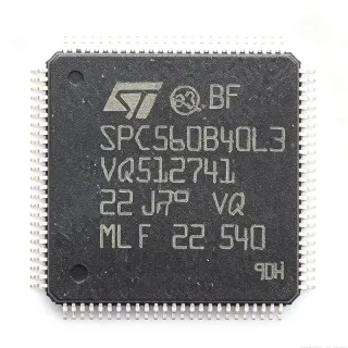
STM32L162VET6 - 512KB Flash Ultra-Low-Power MCU | STMicroelectronics
MPN: STM32L162VET6 ✓ Active| Qty | Unit Price | Extended |
|---|---|---|
| 1 | $8.5 | $8.50 |
| 10 | $7.65 | $76.50 |
| 100 | $6.8 | $680.00 |
| 500 | $6.12 | $3,060.00 |
| 1,000 | $5.44 | $5,440.00 |
STM32L162VET6 Overview
An ultra-low-power microcontroller (MCU) is a system-on-chip that combines a processor core, memory, and peripherals while minimizing power consumption to extend battery life. The STM32L1 series is STMicroelectronics' flagship ultra-low-power family, positioned within the broader hierarchy of microcontrollers -> 32-bit MCUs -> ARM Cortex-M based MCUs -> STM32 family. These devices are essential in IoT, wearable, and portable medical devices where energy efficiency is critical.
Key features include multiple low-power modes (Sleep, Low-power Run, Low-power Sleep, Stop with RTC, Standby with RTC), a 12-bit ADC with hardware oversampling, a 12-bit DAC, an LCD driver supporting up to 8x40 segments, and an AES-128 hardware encryption engine. The device operates from 1.8V to 3.6V and supports a wide temperature range of -40°C to +85°C. Its ultra-low-power design achieves 230 µA/MHz in Run mode and 0.3 µA in Standby mode with RTC, making it ideal for energy-harvesting and long-life battery applications.
The STM32L162VET6 is built on a 130nm ultra-low-leakage process technology, enabling industry-leading power efficiency. The Cortex-M3 core includes a memory protection unit (MPU) and supports single-cycle multiplication and hardware division. The device features a flexible clock tree with multiple internal and external oscillators, including a 32 kHz RTC oscillator and a 16 MHz HSI RC oscillator, allowing designers to optimize performance versus power consumption.
Typical applications include smart meters, medical devices such as glucose monitors and hearing aids, industrial sensors, and portable consumer electronics. The integrated LCD controller and AES encryption make it particularly suitable for secure, display-equipped battery-powered devices. The USB 2.0 full-speed interface with internal PHY enables direct connectivity to hosts for data logging and firmware updates.
When designing with this MCU, careful attention to the power supply decoupling and clock configuration is essential. Use a 1 µF and 100 nF capacitor pair on each VDD pin, and select the appropriate low-power mode based on wake-up latency requirements. The STM32L162VET6 supports in-application programming (IAP) via USART, SPI, or USB, facilitating field firmware updates.
Drop-in alternatives for STM32L162VET6 — same package, pin-to-pin compatible. Different-package parts requiring PCB rework are excluded.
Quick Comparison Tool — Select alternative parts for side-by-side comparison:
STM32L162VET6TR
✅ Drop-In📋 Reference alternative (not in catalog)
STM32L152VET6
✅ Drop-In📋 Reference alternative (not in catalog)
STM32L162VET6
✅ Drop-In✓ In Stock
$5.44 / Unit
View Datasheet →STM32L151VET6
✅ Drop-In ⚠️ Specs Unverified📋 Reference alternative (not in catalog)
STM32L152VET6TR
✅ Drop-In ⚠️ Specs Unverified📋 Reference alternative (not in catalog)
STM32L162VCT6
✅ Drop-In ⚠️ Specs Unverified📋 Reference alternative (not in catalog)
STM32L162VET6 Maximum Ratings & Electrical Characteristics
| Core | ARM Cortex-M3 |
| Max Clock Frequency | 32 MHz |
| Flash Memory | 512 KB |
| SRAM | 80 KB |
| Supply Voltage | 1.8 V to 3.6 V |
| Operating Temperature | -40°C to +85°C |
| Package | LQFP-100 (14x14 mm) |
| GPIO Pins | 83 |
| ADC | 12-bit, 16 channels |
| DAC | 12-bit, 2 channels |
| LCD Controller | 8x40 segments |
| AES Encryption | 128-bit hardware |
| USB | 2.0 Full-speed device |
| Low-power Run Mode | 230 µA/MHz |
| Standby Mode with RTC | 0.3 µA |
| RoHS | Compliant |
STM32L162VET6 Pin Configuration
| Pin 1 | PE2 — GPIO / alternate functions |
| Pin 2 | PE3 — GPIO / alternate functions |
| Pin 3 | PE4 — GPIO / alternate functions |
| Pin 4 | PE5 — GPIO / alternate functions |
| Pin 5 | PE6 — GPIO / alternate functions |
| Pin 6 | VBAT — Battery backup supply |
| Pin 7 | PC13 — GPIO / RTC tamper |
| Pin 8 | PC14 — GPIO / OSC32_IN |
| Pin 9 | PC15 — GPIO / OSC32_OUT |
| Pin 10 | PF0 — GPIO / OSC_IN |
| Pin 11 | PF1 — GPIO / OSC_OUT |
| Pin 12 | NRST — Reset (active low) |
| Pin 13 | PC0 — GPIO / ADC input |
| Pin 14 | PC1 — GPIO / ADC input |
| Pin 15 | PC2 — GPIO / ADC input |
| Pin 16 | PC3 — GPIO / ADC input |
| Pin 17 | VDD — Power supply |
| Pin 18 | VSS — Ground |
| Pin 19 | PC4 — GPIO / ADC input |
| Pin 20 | PC5 — GPIO / ADC input |
| Pin 21 | PB0 — GPIO / ADC input |
| Pin 22 | PB1 — GPIO / ADC input |
| Pin 23 | PB2 — GPIO / BOOT1 |
| Pin 24 | PB10 — GPIO / I2C2_SCL |
| Pin 25 | PB11 — GPIO / I2C2_SDA |
| Pin 26 | VDD — Power supply |
| Pin 27 | VSS — Ground |
| Pin 28 | PB12 — GPIO / SPI2_NSS |
| Pin 29 | PB13 — GPIO / SPI2_SCK |
| Pin 30 | PB14 — GPIO / SPI2_MISO |
| Pin 31 | PB15 — GPIO / SPI2_MOSI |
| Pin 32 | PD8 — GPIO / USART3_TX |
| Pin 33 | PD9 — GPIO / USART3_RX |
| Pin 34 | PD10 — GPIO / USART3_CK |
| Pin 35 | PD11 — GPIO / USART3_CTS |
| Pin 36 | PD12 — GPIO / USART3_RTS |
| Pin 37 | PD13 — GPIO / TIM4_CH2 |
| Pin 38 | PD14 — GPIO / TIM4_CH3 |
| Pin 39 | PD15 — GPIO / TIM4_CH4 |
| Pin 40 | VDD — Power supply |
| Pin 41 | VSS — Ground |
| Pin 42 | PC6 — GPIO / TIM3_CH1 |
| Pin 43 | PC7 — GPIO / TIM3_CH2 |
| Pin 44 | PC8 — GPIO / TIM3_CH3 |
| Pin 45 | PC9 — GPIO / TIM3_CH4 |
| Pin 46 | PA0 — GPIO / ADC input / WKUP |
| Pin 47 | PA1 — GPIO / ADC input |
| Pin 48 | PA2 — GPIO / USART2_TX |
| Pin 49 | PA3 — GPIO / USART2_RX |
| Pin 50 | PA4 — GPIO / DAC_OUT1 |
| Pin 51 | PA5 — GPIO / DAC_OUT2 |
| Pin 52 | PA6 — GPIO / SPI1_MISO |
| Pin 53 | PA7 — GPIO / SPI1_MOSI |
| Pin 54 | VDD — Power supply |
| Pin 55 | VSS — Ground |
| Pin 56 | PC4 — GPIO / ADC input |
| Pin 57 | PC5 — GPIO / ADC input |
| Pin 58 | PB0 — GPIO / ADC input |
| Pin 59 | PB1 — GPIO / ADC input |
| Pin 60 | PB2 — GPIO / BOOT1 |
| Pin 61 | PB10 — GPIO / I2C2_SCL |
| Pin 62 | PB11 — GPIO / I2C2_SDA |
| Pin 63 | VDD — Power supply |
| Pin 64 | VSS — Ground |
| Pin 65 | PB12 — GPIO / SPI2_NSS |
| Pin 66 | PB13 — GPIO / SPI2_SCK |
| Pin 67 | PB14 — GPIO / SPI2_MISO |
| Pin 68 | PB15 — GPIO / SPI2_MOSI |
| Pin 69 | PD8 — GPIO / USART3_TX |
| Pin 70 | PD9 — GPIO / USART3_RX |
| Pin 71 | PD10 — GPIO / USART3_CK |
| Pin 72 | PD11 — GPIO / USART3_CTS |
| Pin 73 | PD12 — GPIO / USART3_RTS |
| Pin 74 | PD13 — GPIO / TIM4_CH2 |
| Pin 75 | PD14 — GPIO / TIM4_CH3 |
| Pin 76 | PD15 — GPIO / TIM4_CH4 |
| Pin 77 | VDD — Power supply |
| Pin 78 | VSS — Ground |
| Pin 79 | PC6 — GPIO / TIM3_CH1 |
| Pin 80 | PC7 — GPIO / TIM3_CH2 |
| Pin 81 | PC8 — GPIO / TIM3_CH3 |
| Pin 82 | PC9 — GPIO / TIM3_CH4 |
| Pin 83 | PA0 — GPIO / ADC input / WKUP |
| Pin 84 | PA1 — GPIO / ADC input |
| Pin 85 | PA2 — GPIO / USART2_TX |
| Pin 86 | PA3 — GPIO / USART2_RX |
| Pin 87 | PA4 — GPIO / DAC_OUT1 |
| Pin 88 | PA5 — GPIO / DAC_OUT2 |
| Pin 89 | PA6 — GPIO / SPI1_MISO |
| Pin 90 | PA7 — GPIO / SPI1_MOSI |
| Pin 91 | VDD — Power supply |
| Pin 92 | VSS — Ground |
| Pin 93 | PC4 — GPIO / ADC input |
| Pin 94 | PC5 — GPIO / ADC input |
| Pin 95 | PB0 — GPIO / ADC input |
| Pin 96 | PB1 — GPIO / ADC input |
| Pin 97 | PB2 — GPIO / BOOT1 |
| Pin 98 | PB10 — GPIO / I2C2_SCL |
| Pin 99 | PB11 — GPIO / I2C2_SDA |
| Pin 100 | VDD — Power supply |
Typical Applications
STM32L162VET6 is suitable for 6 applications: Smart Meters, Medical Devices, Industrial Sensors, Portable Consumer Electronics, IoT Devices, Security Systems.
Smart Meters
The STM32L162VET6 is ideal for smart meters due to its ultra-low power consumption, integrated LCD controller for display, and AES-128 encryption for secure data communication. In a typical smart meter, the MCU reads sensor data, processes it, and communicates via wireless or wired interfaces while maintaining long battery life. The 512 KB Flash allows storing extensive metering data and firmware updates. The low-power modes enable the meter to run for years on a single battery, and the AES engine secures communication with the utility network.
Recommended
Medical Devices
The STM32L162VET6 is well-suited for portable medical devices such as glucose monitors, hearing aids, and pulse oximeters. Its ultra-low-power operation extends battery life, critical for wearable devices. The integrated ADC and DAC enable precise sensor signal conditioning, while the LCD controller can drive small displays for user feedback. The AES encryption ensures patient data security. The device's small footprint and low power make it ideal for continuous health monitoring.
Recommended
Industrial Sensors
In industrial environments, the STM32L162VET6 can be used in wireless sensor nodes for condition monitoring, temperature sensing, and pressure measurement. Its wide supply voltage range (1.8V-3.6V) allows operation from industrial power rails or batteries. The multiple communication interfaces (USART, SPI, I2C) enable connectivity to various sensors and actuators. The low-power modes are essential for battery-powered nodes that must operate for years without maintenance.
Recommended
Portable Consumer Electronics
The STM32L162VET6 is perfect for portable consumer devices like fitness trackers, smart watches, and remote controls. Its ultra-low-power consumption ensures long battery life, and the integrated LCD controller can drive small displays. The USB interface allows easy charging and data transfer. The AES encryption can secure user data. The device's small package and rich peripheral set make it a versatile choice for compact designs.
Recommended
IoT Devices
The STM32L162VET6 is an excellent choice for IoT edge devices that require low power and secure communication. Its AES-128 encryption engine ensures secure data transmission, and the ultra-low-power modes enable battery-powered operation for extended periods. The device can interface with various sensors and communication modules (Wi-Fi, BLE, LoRa) via USART, SPI, or I2C. The 512 KB Flash provides ample space for application code and data logging.
Recommended
Security Systems
The STM32L162VET6 is suitable for security systems such as access control panels, alarm systems, and surveillance cameras. Its AES encryption ensures secure communication with central monitoring stations. The LCD controller can display system status, and the multiple GPIOs can interface with sensors and actuators. The low-power modes allow battery backup operation during power outages.
Recommended
Recommended Products Summary
Engineering reference data for STM32L162VET6 — comparison, design guidance, and compliance information.
Selection Guide
Comparison with Alternatives
| Parameter | This Product | STM32L162VET6TR | STM32L152VET6 | STM32L151VET6 | STM32L162VCT6 |
|---|---|---|---|---|---|
| Package | LQFP-100 | LQFP-100 - same | LQFP-100 - same | LQFP-100 - same | LQFP-100 - same |
| Brand | STMicroelectronics | STMicroelectronics | STMicroelectronics | STMicroelectronics | STMicroelectronics |
| Core | ARM Cortex-M3 | ARM Cortex-M3 | ARM Cortex-M3 | ARM Cortex-M3 | ARM Cortex-M3 |
| Max Clock Frequency | 32 MHz | 32 MHz | 32 MHz | 32 MHz | 32 MHz |
| Flash Memory | 512 KB | 512 KB | 512 KB | 512 KB | 256 KB |
| SRAM | 80 KB | 80 KB | 80 KB | 80 KB | 32 KB |
| AES Encryption | Yes (128-bit) | Yes (128-bit) | No | No | Yes (128-bit) |
| LCD Controller | Yes (8x40) | Yes (8x40) | Yes (8x40) | No | Yes (8x40) |
| Supply Voltage | 1.8V - 3.6V | 1.8V - 3.6V | 1.8V - 3.6V | 1.8V - 3.6V | 1.8V - 3.6V |
| Standby Current | 0.3 µA | 0.3 µA | 0.3 µA | 0.3 µA | 0.3 µA |
Key Differentiators
- Integrated AES-128 hardware encryption (vs STM32L152VET6)
- Integrated LCD controller (vs STM32L151VET6)
- Larger Flash and SRAM (vs STM32L162VCT6)
Design Notes
Decouple each VDD pin with a 100 nF ceramic capacitor placed as close as possible to the pin, and add a 1 µF capacitor at the main power entry. For the VDDA pin, use a 1 µF and 100 nF pair to ensure stable ADC reference. The VBAT pin should be connected to a backup battery or tied to VDD through a diode to maintain RTC operation during main power loss.
For the LQFP-100 package, ensure a solid ground plane under the device. Route the crystal oscillator (OSC_IN/OSC_OUT) with short traces and keep them away from high-speed digital lines. Place the decoupling capacitors for the crystal as close as possible to the pins. Use a 4-layer PCB with dedicated power and ground planes for optimal EMC performance.
Do not leave unused GPIO pins floating; configure them as outputs or enable internal pull-ups/pull-downs to avoid excessive leakage. When using the LCD controller, ensure the LCD voltage (VLCD) is properly generated and decoupled. For low-power modes, disable unused peripherals and clocks to achieve the specified standby current. Also, note that the BOOT0 pin must be tied to a defined level to avoid accidental boot mode changes.
Compliance Information
RoHS compliant per STMicroelectronics product page. Not AEC-Q100 qualified (not intended for automotive).