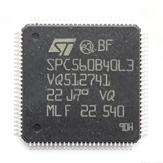
SPC560P50L3 - 32-bit MCU, 512KB Flash, 64MHz | STMicroelectronics
MPN: SPC560P50L3 ✓ Active| Qty | Unit Price | Extended |
|---|---|---|
| 1 | $12.5 | $12.50 |
| 10 | $11.25 | $112.50 |
| 100 | $9.8 | $980.00 |
| 500 | $8.5 | $4,250.00 |
| 1,000 | $7.2 | $7,200.00 |
SPC560P50L3 Overview
A microcontroller (MCU) is a compact integrated circuit designed to govern a specific operation in an embedded system. It contains a processor core, memory, and programmable input/output peripherals on a single chip. MCUs are the backbone of automotive electronics, industrial control, and IoT devices, providing the intelligence to process sensor data, control actuators, and communicate over networks. The SPC560P50L3 belongs to the family of 32-bit automotive microcontrollers, which offer higher performance and memory capacity compared to 8-bit or 16-bit counterparts, enabling complex control algorithms and connectivity.
Key features of the SPC560P50L3 include a 64 MHz e200z0h core, 512 KB flash with ECC, 48 KB SRAM, and a rich set of peripherals such as multiple CAN, LIN, SPI, and I2C interfaces. It also integrates a 10-bit ADC with up to 16 channels, PWM timers, and a flexible timer module (FTM) for motor control. The device is AEC-Q100 qualified, ensuring reliability for automotive environments, and supports a wide operating temperature range from -40°C to +125°C.
The SPC560P50L3 is built on ST's advanced 90nm process technology, offering a balance of performance and power efficiency. The e200z0h core is a single-issue, 32-bit Power Architecture core with variable-length encoding (VLE) for code density, reducing memory footprint. The MCU includes a memory protection unit (MPU) and a cyclic redundancy check (CRC) unit for enhanced safety and data integrity, aligning with ISO 26262 functional safety requirements.
Typical applications include automotive body control modules, gateway modules, and industrial automation. In body control, the SPC560P50L3 manages lighting, wipers, and power windows, while in gateways it routes messages between CAN and LIN networks. Its robust communication interfaces and high-temperature operation make it ideal for under-hood and in-cabin electronics.
When designing with this MCU, ensure proper decoupling of the power supply pins and a stable clock source. The device supports both external crystal and internal RC oscillator, with a phase-locked loop (PLL) for frequency multiplication. For safety-critical applications, utilize the built-in self-test (BIST) and watchdog timer to meet ISO 26262 requirements.
Drop-in alternatives for SPC560P50L3 — same package, pin-to-pin compatible. Different-package parts requiring PCB rework are excluded.
Variants in this series
Same-series models that are drop-in compatible with SPC560P50L3 (same form factor and footprint) — differing in ADC, AEC-Q100, Flash Memory, Package.
Quick Comparison Tool — Select alternative parts for side-by-side comparison:
SPC560P50L3CEFAR
✅ Drop-In📋 Reference alternative (not in catalog)
SPC560P50L3BEABR
✅ Drop-In📋 Reference alternative (not in catalog)
SPC560P50L5CEFBY
✅ Drop-In✓ In Stock
$8.1 / Unit
View Datasheet →SPC560P44L3
✅ Drop-In ⚠️ Specs Unverified📋 Reference alternative (not in catalog)
SPC560P44L5
✅ Drop-In ⚠️ Specs Unverified📋 Reference alternative (not in catalog)
SPC560P50L3 Maximum Ratings & Electrical Characteristics
| Core | e200z0h (Power Architecture) |
| Maximum Frequency | 64 MHz |
| Flash Memory | 512 KB (with ECC) |
| SRAM | 48 KB |
| Supply Voltage | 3.3V to 5V |
| Package | LQFP-100 (14x14 mm) |
| Operating Temperature | -40°C to +125°C |
| ADC | 10-bit, up to 16 channels |
| CAN Interfaces | Multiple (up to 3) |
| LIN Interfaces | Multiple (up to 3) |
| SPI Interfaces | Multiple (up to 3) |
| I2C Interfaces | Multiple (up to 2) |
| PWM Timers | Yes |
| Flexible Timer Module (FTM) | Yes |
| AEC-Q100 | Qualified |
| Process Technology | 90nm |
| Memory Protection Unit (MPU) | Yes |
| CRC Unit | Yes |
| Watchdog Timer | Yes |
| RoHS | Compliant |
SPC560P50L3 Pin Configuration
| Pin 1 | VDD — Digital power supply |
| Pin 2 | VSS — Digital ground |
| Pin 3 | VDDA — Analog power supply |
| Pin 4 | VSSA — Analog ground |
| Pin 5 | RESET — Reset input |
| Pin 6 | XTAL — Crystal oscillator input |
| Pin 7 | EXTAL — Crystal oscillator output |
| Pin 8 | CAN0_TX — CAN0 transmit |
| Pin 9 | CAN0_RX — CAN0 receive |
| Pin 10 | LIN0_TX — LIN0 transmit |
| Pin 11 | LIN0_RX — LIN0 receive |
| Pin 12 | SPI0_SCK — SPI0 clock |
| Pin 13 | SPI0_MOSI — SPI0 master out slave in |
| Pin 14 | SPI0_MISO — SPI0 master in slave out |
| Pin 15 | I2C0_SCL — I2C0 clock |
| Pin 16 | I2C0_SDA — I2C0 data |
| Pin 17 | ADC0_IN0 — ADC0 channel 0 |
| Pin 18 | ADC0_IN1 — ADC0 channel 1 |
| Pin 19 | PWM0 — PWM output 0 |
| Pin 20 | PWM1 — PWM output 1 |
Typical Applications
SPC560P50L3 is suitable for 6 applications: Automotive Body Control Module, Automotive Gateway Module, Industrial Automation Controller, Electric Power Steering (EPS) Control, Engine Control Unit (ECU), Battery Management System (BMS).
Automotive Body Control Module
The SPC560P50L3 is ideal for automotive body control modules (BCMs) that manage lighting, wipers, power windows, and central locking. Its 64 MHz e200z0h core provides sufficient processing power for real-time control algorithms, while the multiple CAN and LIN interfaces enable seamless communication with other vehicle ECUs. The AEC-Q100 qualification and -40°C to +125°C operating range ensure reliable operation in harsh automotive environments. The 10-bit ADC with 16 channels allows direct connection to analog sensors for monitoring switch positions, temperature, and voltage levels. The flexible timer module (FTM) supports PWM generation for dimming lights and controlling motor speeds. With 512 KB flash and 48 KB SRAM, the BCM can store complex diagnostic routines and calibration data. The device's low power consumption in standby mode helps reduce battery drain when the vehicle is off. Overall, the SPC560P50L3 provides a cost-effective, reliable solution for BCM applications, reducing component count and PCB area.
Recommended
Automotive Gateway Module
In automotive gateway modules, the SPC560P50L3 acts as a central hub routing messages between different vehicle networks, such as CAN, LIN, and proprietary buses. Its multiple CAN and LIN interfaces (up to 3 each) allow it to bridge communication between the powertrain, chassis, body, and infotainment domains. The 64 MHz core and 512 KB flash provide ample resources for message filtering, routing tables, and diagnostic services. The device's CRC unit and memory protection unit (MPU) enhance data integrity and security, which are critical for gateway functions. The SPC560P50L3's support for both 3.3V and 5V supply voltages simplifies interfacing with various transceivers and sensors. Its wide operating temperature range ensures reliable operation in the vehicle's thermal environment. The built-in self-test (BIST) and watchdog timer support functional safety requirements, making it suitable for safety-relevant gateway applications. The LQFP-100 package offers a compact footprint for space-constrained gateway PCBs.
Recommended
Industrial Automation Controller
The SPC560P50L3 is well-suited for industrial automation controllers that require robust communication and real-time control. Its 64 MHz e200z0h core can handle complex control loops for motor control, process monitoring, and machine sequencing. The multiple SPI and I2C interfaces allow connection to external sensors, ADCs, DACs, and communication modules. The 10-bit ADC with 16 channels enables direct interfacing with analog sensors for temperature, pressure, and flow measurement. The flexible timer module (FTM) supports PWM generation for driving motors and actuators. The device's wide operating temperature range (-40°C to +125°C) makes it suitable for harsh industrial environments. The AEC-Q100 qualification, although designed for automotive, also indicates high reliability that is beneficial for industrial applications. The 512 KB flash and 48 KB SRAM provide ample space for control algorithms and data logging. The SPC560P50L3's support for CAN and LIN interfaces allows integration into existing industrial networks, reducing system complexity.
Recommended
Electric Power Steering (EPS) Control
The SPC560P50L3 is suitable for electric power steering (EPS) control units, where real-time processing and safety are paramount. The 64 MHz e200z0h core can execute complex motor control algorithms, such as field-oriented control (FOC) for brushless DC motors, with sufficient margin. The flexible timer module (FTM) provides high-resolution PWM outputs for driving the motor inverter. The 10-bit ADC with 16 channels allows precise measurement of motor currents, rotor position, and torque sensor signals. The device's multiple CAN interfaces enable communication with the vehicle's stability control and engine management systems. The memory protection unit (MPU) and CRC unit support functional safety requirements, helping to achieve ISO 26262 compliance. The AEC-Q100 qualification and -40°C to +125°C operating range ensure reliable operation under the hood. The 512 KB flash and 48 KB SRAM provide ample space for control software and calibration data. The SPC560P50L3's robust design makes it a reliable choice for EPS applications.
Recommended
Engine Control Unit (ECU)
The SPC560P50L3 can be used in engine control units (ECUs) for managing fuel injection, ignition timing, and emission control. Its 64 MHz e200z0h core provides the computational power needed for real-time engine control algorithms. The multiple CAN interfaces allow communication with other ECUs and diagnostic tools. The 10-bit ADC with 16 channels is used to read sensors such as throttle position, manifold pressure, and coolant temperature. The flexible timer module (FTM) generates precise PWM signals for fuel injectors and ignition coils. The device's wide operating temperature range and AEC-Q100 qualification ensure reliable operation in the engine compartment. The 512 KB flash and 48 KB SRAM provide ample space for engine maps and control strategies. The built-in self-test (BIST) and watchdog timer enhance system reliability. The SPC560P50L3's robust communication interfaces and high-temperature operation make it ideal for engine control applications.
Recommended
Battery Management System (BMS)
The SPC560P50L3 is suitable for battery management systems (BMS) in electric and hybrid vehicles. Its 64 MHz e200z0h core can handle complex battery monitoring and balancing algorithms. The 10-bit ADC with 16 channels allows accurate measurement of cell voltages, currents, and temperatures. The multiple CAN interfaces enable communication with the vehicle's main controller and charging systems. The device's wide operating temperature range (-40°C to +125°C) is essential for battery packs that experience extreme temperatures. The AEC-Q100 qualification ensures reliability in automotive environments. The 512 KB flash and 48 KB SRAM provide ample space for battery state-of-charge (SoC) and state-of-health (SoH) algorithms. The CRC unit and memory protection unit (MPU) enhance data integrity and safety. The SPC560P50L3's robust communication interfaces and high-temperature operation make it ideal for BMS applications, ensuring safe and efficient battery operation.
Recommended
Recommended Products Summary
Engineering reference data for SPC560P50L3 — comparison, design guidance, and compliance information.
Selection Guide
Comparison with Alternatives
| Parameter | This Product | SPC560P50L3CEFAR | SPC560P50L3BEABR | SPC560P50L5 |
|---|---|---|---|---|
| Package | LQFP-100 | LQFP-100 | LQFP-100 | LQFP-100 |
| Brand | STMicroelectronics | STMicroelectronics | STMicroelectronics | STMicroelectronics |
| Core | e200z0h | e200z0h | e200z0h | e200z0h |
| Maximum Frequency | 64 MHz | 64 MHz | 64 MHz | 64 MHz |
| Flash Memory | 512 KB | 512 KB | 512 KB | 576 KB |
| SRAM | 48 KB | 48 KB | 48 KB | 40 KB |
| Supply Voltage | 3.3V to 5V | 3.3V to 5V | 3.3V to 5V | 3.3V to 5V |
| Operating Temperature | -40°C to +125°C | -40°C to +125°C | -40°C to +125°C | -40°C to +125°C |
| AEC-Q100 | Qualified | Qualified | Qualified | Qualified |
Key Differentiators
- Higher SRAM capacity (48 KB) compared to SPC560P50L5 (40 KB) (vs SPC560P50L5)
- AEC-Q100 qualified for automotive reliability (vs SPC560P50L3CEFAR)
- Lower cost due to smaller flash (512 KB vs 576 KB) (vs SPC560P50L5)
Design Notes
Ensure proper decoupling of the power supply pins. Place a 100nF ceramic capacitor close to each VDD/VSS pair and a 10uF bulk capacitor near the power input. The SPC560P50L3 operates from 3.3V to 5V, so verify that the supply voltage is within this range under all load conditions. Use a low-ESR capacitor for the analog supply (VDDA) to minimize noise on the ADC reference.
For the LQFP-100 package, ensure a solid ground plane underneath the device to reduce EMI and improve thermal performance. Route high-speed signals such as SPI and CAN with controlled impedance if possible. Keep the crystal oscillator traces short and away from high-current switching signals. Follow ST's layout guidelines in the datasheet for optimal performance.
Do not exceed the absolute maximum ratings for supply voltage and I/O pins. Ensure the reset pin is properly pulled up and that the watchdog timer is configured correctly to avoid unintended resets. When using the internal RC oscillator, be aware of its accuracy and temperature drift; for applications requiring precise timing, use an external crystal. Also, verify that the flash programming voltage is within specification to avoid corruption.
Compliance Information
RoHS compliance is indicated by STMicroelectronics. AEC-Q100 qualification is confirmed for automotive applications. Other compliance details are not explicitly stated in the provided data.