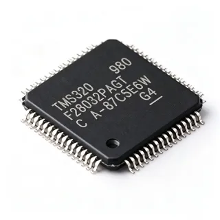
TMS320F28035PAGT - 60MHz C2000 Piccolo MCU 64-TQFP | TI
MPN: TMS320F28035PAGT ✓ Active| Qty | Unit Price | Extended |
|---|---|---|
| 1 | $4.25 | $4.25 |
| 10 | $3.85 | $38.50 |
| 100 | $3.45 | $345.00 |
| 500 | $3.1 | $1,550.00 |
| 1,000 | $2.7 | $2,700.00 |
TMS320F28035PAGT Overview
A microcontroller (MCU) is a compact integrated circuit combining a processor core, memory, and programmable peripherals in one chip. Within the power-management hierarchy, the C2000 family is a specialized MCU class optimized for real-time control, pairing the C28x DSP core with control peripherals such as PWM, ADC, and quadrature encoder interfaces, making it ideal for closed-loop systems in motor drives, power conversion, and industrial automation.
Key features include the 60 MHz C28x 32-bit CPU with an independent CLA floating-point coprocessor that executes control loops in parallel with the main CPU, effectively doubling throughput for time-critical tasks. Memory comprises 128KB flash and 20KB SRAM, protected by a 128-bit security key. Communication peripherals include CAN, LIN, I2C, SPI, and UART, while the internal voltage regulator enables single-rail 3.3V operation, simplifying power supply design.
Architecturally, the C28x core uses a Harvard bus structure with hardware multiply-accumulate units optimized for math-intensive algorithms. High-resolution PWM (HRPWM) plus the fast 12-bit ADC support precise current and voltage regulation loops in digital power stages, enabling switching frequencies and control bandwidths unreachable by general-purpose MCUs.
Typical applications include industrial motor drives, solar inverters, digital power supplies, and power line communications. The integrated analog and PWM peripherals reduce external component count and control-loop latency compared with discrete controller-plus-PWM solutions.
Designers should ensure proper 3.3V decoupling on VDDIO/VDD rails and configure CLA shared-memory access carefully to avoid CPU contention. The T suffix denotes the tray packaging option for the same silicon.
This page synthesizes distributor pricing, drop-in alternatives, and practical design notes not found in the manufacturer datasheet.
Drop-in alternatives for TMS320F28035PAGT — same package, pin-to-pin compatible. Different-package parts requiring PCB rework are excluded.
Variants in this series
Same-series models that are drop-in compatible with TMS320F28035PAGT (same form factor and footprint) — differing in ADC Resolution, Package, Communication Interfaces, Core, Flash Memory.
Quick Comparison Tool — Select alternative parts for side-by-side comparison:
TMS320F28035PAGS
✅ Drop-In📋 Reference alternative (not in catalog)
TMS320F28034PAGS
✅ Drop-In ⚠️ Specs Unverified📋 Reference alternative (not in catalog)
TMS320F28033PAGS
✅ Drop-In ⚠️ Specs Unverified📋 Reference alternative (not in catalog)
TMS320F28032PAGS
✅ Drop-In ⚠️ Specs Unverified📋 Reference alternative (not in catalog)
TMS320F28030PAGS
✅ Drop-In ⚠️ Specs Unverified📋 Reference alternative (not in catalog)
TMS320F28035PAGT Maximum Ratings & Electrical Characteristics
| Core | C28x 32-bit with CLA coprocessor |
| CPU Frequency | 60 MHz (120 MIPS) |
| Flash Memory | 128KB (64K x 16) |
| SRAM | 20KB |
| ADC Resolution | 12-bit |
| ADC Channels | Up to 16 |
| GPIO Count | 33 |
| Supply Voltage | 1.8V core / 3.3V I/O (internal regulator supports single 3.3V rail) |
| Operating Temperature | -40C to +105C |
| Package | 64-TQFP (PAG), 10x10 mm |
| Mounting Type | Surface Mount |
| Communication Interfaces | CAN, LIN, I2C, SPI, UART/SCI |
| PWM | ePWM modules with HRPWM (high-resolution PWM) |
| Security | 128-bit security key |
| Packaging Option | Tray (T suffix) |
| Product Family | C2000 Piccolo TMS320F2803x |
TMS320F28035PAGT 64-tqfp (pag), 10x10 mm Pin Configuration Guide
Pin configuration for TMS320F28035PAGT (64-tqfp (pag), 10x10 mm package). This digital IC includes GPIO, communication interfaces (UART, SPI, I2C), and power pins. Refer to the manufacturer datasheet for alternate pin functions and configuration options. Essential for embedded system design and PCB layout.

No detailed pinout data available for TMS320F28035PAGT.
Refer to the datasheet for full pin configuration.
Typical Applications
TMS320F28035PAGT is suitable for 6 applications: Industrial Motor Drives, Solar Inverters and PV Power Conversion, Digital Power Supplies (LLC, PFC, DC-DC), Power Line Communications (PLC) Modems, Automotive and Industrial HVAC Blowers / Pumps, Test, Measurement and Robotics Control.
Industrial Motor Drives
The TMS320F28035PAGT fits ACIM, PMSM, BLDC, and stepper motor control because its 60 MHz C28x core plus CLA executes field-oriented control (FOC) current loops in parallel, achieving control-loop rates of 10-20 kHz with the main CPU free for speed-loop and communication tasks. The ePWM modules with high-resolution PWM (HRPWM) provide fine duty-cycle resolution for reduced torque ripple, while the fast 12-bit ADC samples phase currents synchronously with PWM edges via ePWM ADC SOC triggering. The eQEP peripheral decodes quadrature encoder feedback at hardware speed. TI's InstaSPIN-enabled controlCARD reference designs for the F2803x class demonstrate complete inverter designs. Designers should route ADC sense lines away from gate-driver switching nodes and use the CLA for the fastest current loop.
Recommended
Solar Inverters and PV Power Conversion
The TMS320F28035PAGT serves string-inverter and microinverter control where its 120 MIPS of C28x+CLA processing runs MPPT algorithms, grid-synchronization (PLL) software, and current-control loops concurrently. The 12-bit ADC, triggered by ePWM SOC events, digitizes PV voltage/current and grid signals with precise timing alignment, and HRPWM enables high switching frequencies (up to several hundred kHz) with fine resolution for LLC or interleaved boost stages. The CAN and UART peripherals support inverter monitoring and grid-protocol interfaces. The integrated 1.8V core regulator permits single 3.3V supply rails in compact power stages. Grid-code compliance (anti-islanding, THD) depends on the control firmware and ADC timing accuracy the F28035's architecture is built to deliver.
Recommended
Digital Power Supplies (LLC, PFC, DC-DC)
The TMS320F28035PAGT is widely used in digitally controlled AC-DC and DC-DC converters. Its ePWM modules support phase-shifted full-bridge, LLC, PFC, and buck topologies with dead-band submodules and cycle-by-cycle current limiting handled in hardware, so protection latency is independent of software. HRPWM delivers 150-ps effective PWM resolution, suppressing limit-cycle oscillation at high switching frequencies. The CLA can close the voltage loop while the C28x CPU manages soft-start, fault handling, and PMBus/I2C telemetry. The 12-bit ADC with multiple SOC triggers samples input/output voltage and switch currents with minimal jitter. TI's digital power reference designs (e.g., PFC + LLC combos) on the F2803x family document firmware frameworks that shorten development cycles significantly.
Recommended
Power Line Communications (PLC) Modems
The TMS320F28035PAGT implements low-voltage and narrowband PLC modems where its C28x DSP heritage runs PRIME, G3-PLC, or proprietary OFDM/FSK physical layers in software. The 12-bit ADC digitizes the coupled line signal while the on-chip PWM plus external AFE handles transmit shaping and amplifier control; the integrated 128-bit security key protects metering firmware. SCI/SPI peripherals interface to host processors and the 20KB SRAM buffers frame data. TI's C2000 PLC development kits pair the F2803x with the AFE031 analog front end for CENELEC A/B/C and FCC band transmission on 50/60 Hz power lines. The 105C temperature rating supports smart-meter environments inside sealed enclosures, and the 60 MHz core leaves headroom for concurrent protocol stacks.
Recommended
Automotive and Industrial HVAC Blowers / Pumps
The TMS320F28035PAGT controls sensorless BLDC blowers, circulation pumps, and fans in HVAC and industrial fluid systems. Its 105C ambient rating tolerates hot control-box environments, while the ePWM and 12-bit ADC implement sensorless back-EMF or sliding-mode observer commutation executed partly on the CLA, keeping the main CPU free for PID speed control and fault diagnostics. Cycle-by-cycle current limiting in the ePWM hardware protects MOSFET bridges during rotor lock events. The internal regulator and low pin count (64-TQFP) reduce board cost in high-volume appliance designs, and the CAN/LIN interface integrates the drive into vehicle or building networks. TI's sensorless FOC reference firmware for the F2803x family provides a validated starting point for 24-48V blower systems.
Recommended
Test, Measurement and Robotics Control
The TMS320F28035PAGT is used in real-time control cards for robotics joints, dynamometers, and custom instrumentation. eQEP modules decode encoder feedback at hardware rate, eCAP captures PWM or pulse-train inputs with 6.7 ns effective resolution at 150 MHz equivalent, and the C28x+CLA pair closes multi-axis current loops deterministically, a key requirement for robotics-safe torque control. The CAN bus links joints intoEtherCAT/CANopen networks via protocol firmware, and the 33 GPIOs drive limit switches and indicator logic. The 128KB flash holds bootloader, control, and profile firmware with the 128-bit security key protecting vendor IP in fielded equipment. TI's controlCARD format (with the F28035 Piccolo) is accepted by major robotics and servo-drive OEM stacks, easing adoption for new control-platform development.
Recommended
Recommended Products Summary
Engineering reference data for TMS320F28035PAGT — comparison, design guidance, and compliance information.
Selection Guide
Comparison with Alternatives
| Parameter | This Product | TMS320F28035PAGS | TMS320F28034PAGS | TMS320F28033PAGS | TMS320F28032PAGS |
|---|---|---|---|---|---|
| Package | 64-TQFP (PAG) 10x10 mm | 64-TQFP (PAG) - same | 64-TQFP (PAG) - same | 64-TQFP (PAG) - same | 64-TQFP (PAG) - same |
| Brand | Texas Instruments | Texas Instruments | Texas Instruments | Texas Instruments | Texas Instruments |
| CPU Frequency | 60 MHz (120 MIPS) | 60 MHz (120 MIPS) | 60 MHz (120 MIPS) | 60 MHz (120 MIPS) | 60 MHz (120 MIPS) |
| Flash Memory | 128KB | 128KB | 64KB | 64KB | 64KB |
| CLA Coprocessor | Yes | Yes | Yes | Yes | No |
| Pin Compatibility | 64-TQFP PAG pinout | Pin-to-pin identical | Pin-to-pin identical | Pin-to-pin identical | Pin-to-pin identical |
| Typical Use | Full-feature motor drive / digital power control | Identical; alternate packing flow | Cost-reduced designs fitting 64KB flash | Cost-reduced designs fitting 64KB flash | Basic control loops without CLA offload |
Key Differentiators
- Full 128KB flash with CLA coprocessor (vs TMS320F28034PAGS)
- Extended 105C temperature rating (vs TMS320F28033PAGS)
- Identical silicon to PAGS at tray-pack cost (vs TMS320F28035PAGS)
Design Notes
The TMS320F28035PAGT integrates a 1.8V core regulator, so the board needs only a single 3.3V supply on VDDIO/VDD. Follow the TI datasheet decoupling recommendation: place 1.1 uF plus 0.1 uF ceramics within 2 mm of each VDD pin, and keep the VDD (regulator output) net on a local plane. Estimated: total core current is on the order of 100-200 mA at 60 MHz (verify against the datasheet current-consumption tables), so a 500 mA 3.3V LDO provides adequate margin.
Route ADC inputs (ADCINA/B channels) as short, guarded traces away from ePWM gate-driver signals; sample currents synchronously with PWM center using the ePWM SOC trigger to avoid switching noise aliasing into 12-bit readings. Place the external crystal within 10 mm of XCLKIN/X1 pins with ground guard rings. Use a solid ground plane under the 64-TQFP and connect the exposed thermal pattern per TI layout guidelines.
CLA shared memory is arbitrated between the C28x CPU and CLA - conflicting simultaneous access stalls the pipeline and corrupts loop timing if the RAM GSx allocation is not planned. Assign CLA-exclusive message RAM for control variables. Also, GPIO Mux defaults: many pins reset to GPIO input with pullup - configure peripheral muxes before enabling PWM outputs, or gate drivers may see glitch pulses at boot.
Compliance Information
TI C2000 commercial/industrial parts are RoHS-compliant and lead-free per TI product pages. AEC-Q100 variant availability should be confirmed against TI's automotive catalog (e.g., TMS320F28035-Q1).