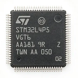
STM32F105VCT7 - 72MHz Cortex-M3 MCU 256KB Flash | STMicroelectronics
N.º da peça: STM32F105VCT7 ✓ Ativo| Qtd. | Preço unitário | Total |
|---|---|---|
| 1 | $11.85 | $11,85 |
| 10 | $10.65 | $106,50 |
| 100 | $9.45 | $945,00 |
| 500 | $8.5 | $4.250,00 |
| 1.000 | $7.65 | $7.650,00 |
STM32F105VCT7 Visão geral
An MCU (microcontroller unit) is a single-chip computer containing a processor core, program memory, data memory, and integrated peripherals. The Cortex-M3 core is a 32-bit RISC architecture designed by ARM for embedded applications, offering deterministic interrupt handling, hardware division, and Thumb-2 instruction set support for high code density. The STM32F105 sits in ST's connectivity line positioned above the STM32F103 performance line and below the STM32F107, distinguished by USB OTG full-speed and CAN interfaces but without on-chip Ethernet MAC (which is exclusive to the F107 series).
Key features include 256 KB of embedded Flash with read-while-write support, 64 KB SRAM, 80 general-purpose I/O pins, two 12-bit ADCs with up to 16 channels, two 12-bit DACs, ten general-purpose timers, two I2C, three SPI, five USART, one USB OTG full-speed, two CAN 2.0B interfaces, and an SDIO interface. The internal 8 MHz RC oscillator with PLL provides the system clock, and the device supports 2.0 V to 3.6 V operating voltage.
Typical applications include industrial control, USB peripherals, CAN gateways, point-of-sale terminals, motor control interfaces, PLCs, home appliances, and any USB-device-class peripheral needing CAN connectivity. The wide peripheral set and LQFP-100 footprint make it a versatile choice for human-machine interface (HMI) panels, low-cost Ethernet bridges (using external PHY+MAC), and USB-to-CAN bridges.
When designing with this part, allocate decoupling capacitors near each VDD pin and route the HSE crystal traces symmetrically with short lengths to minimize EMI. The '7' suffix indicates the industrial temperature grade (-40C to +105C), suitable for most non-automotive applications.
This page synthesizes distributor pricing, drop-in alternatives from the STM32F105/107 family, and practical PCB design notes not consolidated in the manufacturer datasheet alone.
Alternativas drop-in para STM32F105VCT7 — mesmo encapsulamento, compatível pino a pino. Peças de encapsulamento diferente que exigem retrabalho na PCB são excluídas.
Variantes desta série
Modelos da mesma série compatíveis como drop-in com STM32F105VCT7 (mesmo formato e footprint) — diferindo em Timers, ADC, Package, DAC, Operating Temperature.
Ferramenta de comparação rápida — selecione peças alternativas para comparação lado a lado:
STM32F107VCT7
✅ Drop-In📋 Alternativa de referência (fora do catálogo)
STM32F105VCT6
✅ Drop-In✓ Em estoque
$5.4 / unidade
STM32F105VCT7TR
✅ Drop-In📋 Alternativa de referência (fora do catálogo)
STM32F103VCT6
✅ Drop-In✓ Em estoque
$2.68 / unidade
Ver ficha técnica →GD32F303VCT6
✅ Drop-In📋 Alternativa de referência (fora do catálogo)
STM32F105VCT7 Classificações máximas e características elétricas
| Core | ARM Cortex-M3 32-bit RISC |
| Frequência máxima de clock | 72 MHz |
| Program Memory (Flash) | 256 KB (256K x 8) |
| RAM | 64 KB |
| Number of I/O Pins | 80 |
| Encapsulamento | 100-LQFP (14x14 mm) |
| Tensão de alimentação | 2.0 V to 3.6 V |
| Temperatura de operação | -40C to +105C (Grade 7) |
| ADC | 2 x 12-bit, up to 16 channels |
| DAC | 2 x 12-bit |
| Timers | 10 (general-purpose + advanced-control) |
| Communication Interfaces | 5 USART, 3 SPI, 2 I2C, 2 CAN, 1 USB OTG FS, 1 SDIO |
| Tipo de montagem | Surface Mount |
| Packaging | Tray |
| Status RoHS | Compliant |
Configuração de pinos do STM32F105VCT7
| Pino 1 | PE2 — GPIO PE2, TRACECLK (trace clock) |
| Pino 2 | PE3 — GPIO PE3, TRACED0 |
| Pino 3 | PE4 — GPIO PE4, TRACED1 |
| Pino 4 | PE5 — GPIO PE5, TRACED2 |
| Pino 5 | PE6 — GPIO PE6, TRACED3 |
| Pino 6 | VBAT — Battery supply for RTC and backup registers |
| Pino 7 | PC13 — GPIO PC13, TAMPER-RTC (anti-tamper / RTC) |
| Pino 8 | PC14 — GPIO PC14, OSC32_IN (32.768 kHz crystal) |
| Pino 9 | PC15 — GPIO PC15, OSC32_OUT (32.768 kHz crystal) |
| Pino 10 | VSS_5 — Ground |
| Pino 11 | VDD_5 — Digital supply voltage 2.0-3.6 V |
| Pino 12 | OSC_IN — External clock input / HSE crystal input |
| Pino 13 | OSC_OUT — HSE crystal output |
| Pino 14 | NRST — Reset input (active low) |
| Pino 15 | PC0 — GPIO PC0, ADC1_IN10 |
| Pino 16 | PC1 — GPIO PC1, ADC1_IN11 |
| Pino 17 | PC2 — GPIO PC2, ADC1_IN12 |
| Pino 18 | PC3 — GPIO PC3, ADC1_IN13 |
| Pino 19 | VSSA — Analog ground |
| Pino 20 | VREF+ — ADC reference voltage positive |
| Pino 21 | VDDA — Analog supply voltage 2.0-3.6 V |
| Pino 22 | PA0 — GPIO PA0, WKUP, ADC1_IN0, TIM2_CH1 |
| Pino 23 | PA1 — GPIO PA1, ADC1_IN1, TIM2_CH2 |
| Pino 24 | PA2 — GPIO PA2, USART2_TX, ADC1_IN2, TIM2_CH3 |
| Pino 25 | PA3 — GPIO PA3, USART2_RX, ADC1_IN3, TIM2_CH4 |
| Pino 26 | VSS_4 — Ground |
| Pino 27 | VDD_4 — Digital supply voltage 2.0-3.6 V |
| Pino 28 | PA4 — GPIO PA4, SPI1_NSS, USART2_CK, ADC1_IN4 |
| Pino 29 | PA5 — GPIO PA5, SPI1_SCK, ADC1_IN5, DAC_OUT2 |
| Pino 30 | PA6 — GPIO PA6, SPI1_MISO, ADC1_IN6, TIM3_CH1, DAC_OUT1 |
| Pino 31 | PA7 — GPIO PA7, SPI1_MOSI, ADC1_IN7, TIM3_CH2 |
| Pino 32 | PB0 — GPIO PB0, ADC1_IN8, TIM3_CH3 |
| Pino 33 | PB1 — GPIO PB1, ADC1_IN9, TIM3_CH4 |
| Pino 34 | PB2 — GPIO PB2, BOOT1 |
| Pino 35 | VSS_3 — Ground |
| Pino 36 | VDD_3 — Digital supply voltage 2.0-3.6 V |
| Pino 37 | PE7 — GPIO PE7, TIM1_ETR |
| Pino 38 | PE8 — GPIO PE8, TIM1_CH1N |
| Pino 39 | PE9 — GPIO PE9, TIM1_CH1 |
| Pino 40 | PE10 — GPIO PE10, TIM1_CH2N |
| Pino 41 | PE11 — GPIO PE11, TIM1_CH2 |
| Pino 42 | PE12 — GPIO PE12, TIM1_CH3N |
| Pino 43 | PE13 — GPIO PE13, TIM1_CH3 |
| Pino 44 | PE14 — GPIO PE14, TIM1_CH4 |
| Pino 45 | PE15 — GPIO PE15, TIM1_BKIN |
| Pino 46 | PB10 — GPIO PB10, I2C2_SCL, USART3_TX |
| Pino 47 | PB11 — GPIO PB11, I2C2_SDA, USART3_RX |
| Pino 48 | VSS_2 — Ground |
| Pino 49 | VDD_2 — Digital supply voltage 2.0-3.6 V |
| Pino 50 | PB12 — GPIO PB12, SPI2_NSS, I2C2_SMBAI |
| Pino 51 | PB13 — GPIO PB13, SPI2_SCK, USART3_CK |
| Pino 52 | PB14 — GPIO PB14, SPI2_MISO, TIM1_CH2N |
| Pino 53 | PB15 — GPIO PB15, SPI2_MOSI, TIM1_CH3N |
| Pino 54 | PD8 — GPIO PD8, USART3_TX |
| Pino 55 | PD9 — GPIO PD9, USART3_RX |
| Pino 56 | PD10 — GPIO PD10 |
| Pino 57 | PD11 — GPIO PD11 |
| Pino 58 | PD12 — GPIO PD12, TIM4_CH1 |
| Pino 59 | PD13 — GPIO PD13, TIM4_CH2 |
| Pino 60 | PD14 — GPIO PD14, TIM4_CH3 |
| Pino 61 | PD15 — GPIO PD15, TIM4_CH4 |
| Pino 62 | VSS_1 — Ground |
| Pino 63 | VDD_1 — Digital supply voltage 2.0-3.6 V |
| Pino 64 | PC6 — GPIO PC6, TIM8_CH1, SDIO_D6 |
| Pino 65 | PC7 — GPIO PC7, TIM8_CH2, SDIO_D7 |
| Pino 66 | PC8 — GPIO PC8, TIM8_CH3, SDIO_D0 |
| Pino 67 | PC9 — GPIO PC9, TIM8_CH4, SDIO_D1 |
| Pino 68 | PA8 — GPIO PA8, USART1_CK, TIM1_CH1, MCO |
| Pino 69 | PA9 — GPIO PA9, USART1_TX, TIM1_CH2 |
| Pino 70 | PA10 — GPIO PA10, USART1_RX, TIM1_CH3 |
| Pino 71 | PA11 — GPIO PA11, USB_DM, CAN1_RX |
| Pino 72 | PA12 — GPIO PA12, USB_DP, CAN1_TX |
| Pino 73 | PA13 — GPIO PA13, JTMS, SWDIO |
| Pino 74 | VSS_6 — Ground |
| Pino 75 | VDD_6 — Digital supply voltage 2.0-3.6 V |
| Pino 76 | PA14 — GPIO PA14, JTCK, SWDCLK |
| Pino 77 | PA15 — GPIO PA15, JTDI, TIM2_CH1 |
| Pino 78 | PC10 — GPIO PC10, UART4_TX, SDIO_D2 |
| Pino 79 | PC11 — GPIO PC11, UART4_RX, SDIO_D3 |
| Pino 80 | PC12 — GPIO PC12, UART5_TX, SDIO_CK |
| Pino 81 | PD0 — GPIO PD0, CAN1_RX, OSC_IN (remap) |
| Pino 82 | PD1 — GPIO PD1, CAN1_TX, OSC_OUT (remap) |
| Pino 83 | PD2 — GPIO PD2, TIM3_ETR, SDIO_CMD |
| Pino 84 | PD3 — GPIO PD3, USART2_CTS |
| Pino 85 | PD4 — GPIO PD4, USART2_RTS |
| Pino 86 | PD5 — GPIO PD5, USART2_TX |
| Pino 87 | PD6 — GPIO PD6, USART2_RX |
| Pino 88 | PD7 — GPIO PD7, USART2_CK |
| Pino 89 | PB3 — GPIO PB3, JTDO, TIM2_CH2, SPI1_SCK (remap) |
| Pino 90 | PB4 — GPIO PB4, NJTRST, TIM3_CH1, SPI1_MISO (remap) |
| Pino 91 | PB5 — GPIO PB5, TIM3_CH2, SPI1_MOSI (remap), I2C1_SMBAI |
| Pino 92 | PB6 — GPIO PB6, I2C1_SCL, TIM4_CH1, USART1_TX |
| Pino 93 | PB7 — GPIO PB7, I2C1_SDA, TIM4_CH2, USART1_RX |
| Pino 94 | BOOT0 — Boot mode selection (0=main flash, 1=system memory bootloader) |
| Pino 95 | PB8 — GPIO PB8, TIM4_CH3, CAN1_RX (remap) |
| Pino 96 | PB9 — GPIO PB9, TIM4_CH4, CAN1_TX (remap) |
| Pino 97 | PE0 — GPIO PE0, TIM4_ETR |
| Pino 98 | PE1 — GPIO PE1 |
| Pino 99 | VSS_7 — Ground |
| Pino 100 | VDD_7 — Digital supply voltage 2.0-3.6 V |
Aplicações típicas
STM32F105VCT7 é adequado para 6 aplicaçãos: USB-to-CAN Industrial Bridge, Human-Machine Interface (HMI) Panel Controller, USB Barcode Scanner / HID Peripheral, Industrial Control PLC Module, Motor Control Interface Board, Medical Patient Monitoring Data Logger.
USB-to-CAN Industrial Bridge
The STM32F105VCT7's USB OTG full-speed peripheral combined with dual CAN 2.0B controllers (bxCAN) makes it ideal for USB-to-CAN gateway modules used in industrial automation, automotive diagnostics, and CANopen networks. The Cortex-M3 core handles USB CDC class enumeration and CAN frame transmission with deterministic latency, while the 64 KB SRAM buffers CAN traffic bursts. The 256 KB Flash is sufficient for USB stack (e.g., LibUSB) and CANopen/CANFestival protocols. Placed on a small PCB with USB Type-B connector and CAN transceiver (e.g., TJA1050), the part delivers a compact bridge solution operating at 72 MHz with 12 Mbps USB and 1 Mbit/s CAN simultaneously.
Recomendado
Human-Machine Interface (HMI) Panel Controller
The 100-pin LQFP package provides 80 GPIO pins, ample for driving TFT displays, keypads, status LEDs, and external peripherals in HMI panels. The STM32F105VCT7's two 12-bit ADCs support touch-screen digitizer scanning, while the SPI and SDIO peripherals connect to display controllers and microSD storage. Running at 72 MHz, the Cortex-M3 executes FreeRTOS-based UI frameworks smoothly with the 64 KB SRAM accommodating frame buffers. Designers typically pair the MCU with an external TFT controller over SPI and use the FSMC-less GPIO bit-banging for parallel LCD interfaces up to QVGA resolution.
Recomendado
USB Barcode Scanner / HID Peripheral
USB OTG full-speed with on-chip PHY enables direct USB device, host, or dual-role operation without external transceivers, ideal for barcode scanners, RFID readers, and HID peripherals. The STM32F105VCT7 runs USB HID class firmware at 72 MHz with minimal CPU overhead, leaving the 64 KB SRAM and 256 KB Flash available for application code, decode libraries, and buffer storage. The 12 Mbps USB FS bandwidth accommodates keyboard, mouse, barcode wedge, and custom HID reports with sub-1 ms latency. Designers can integrate a USB Type-C interface directly using PA11/PA12 pins with proper ESD protection.
Recomendado
Industrial Control PLC Module
With dual CAN, five USARTs, three SPI, and two I2C interfaces, the STM32F105VCT7 serves as the main processor for compact PLC modules and industrial control boards. The Cortex-M3 at 72 MHz executes IEC 61131-3 runtimes or ladder-logic interpreters, while the 80 GPIO pins drive relays, optocouplers, and isolated digital I/O. The wide 2.0-3.6 V supply tolerance accommodates industrial 24 V systems stepped down to 3.3 V via isolated DC-DC converters. The 105C operating temperature (Grade 7) supports factory-floor cabinets without additional cooling.
Recomendado
Motor Control Interface Board
The STM32F105VCT7's ten timers (including one advanced-control timer with complementary PWM outputs) provide ample PWM channels for brushless DC (BLDC) and stepper motor control interface boards. The 12-bit ADCs sample current and back-EMF signals at up to 1 MSPS, while the Cortex-M3 executes field-oriented control (FOC) algorithms at 72 MHz. Designers typically pair the MCU with external gate drivers (e.g., ST L6234) and use the CAN peripherals for multi-axis communication. The 64 KB SRAM limits FOC to single-axis or basic dual-axis implementations.
Recomendado
Medical Patient Monitoring Data Logger
Medical-grade patient monitoring peripherals (pulse oximeters, thermometers, glucose meters) leverage the STM32F105VCT7's USB OTG for data transfer to PCs, dual CAN for hospital network connectivity, and SDIO for local data storage on microSD cards. The 256 KB Flash stores firmware with embedded USB stack, while the 64 KB SRAM buffers continuous monitoring data. The Cortex-M3 deterministic interrupt response (12-cycle tail-chaining) ensures accurate sensor sampling timing. The -40C to +105C temperature range supports battery-powered portable medical devices.
Recomendado
Resumo dos produtos recomendados
Dados de referência de engenharia para STM32F105VCT7 — comparação, orientação de projeto e informações de conformidade.
Guia de seleção
Comparação com alternativas
| Parâmetro | Este produto | STM32F107VCT7 | STM32F105VCT6 | STM32F105VCT7TR | STM32F103VCT6 | GD32F303VCT6 |
|---|---|---|---|---|---|---|
| Brand | STMicroelectronics | STMicroelectronics | STMicroelectronics | STMicroelectronics | STMicroelectronics | GigaDevice |
| Package | LQFP-100 (14x14 mm) | LQFP-100 (14x14) - same | LQFP-100 (14x14) - same | LQFP-100 (14x14) - same | LQFP-100 (14x14) - same | LQFP-100 (14x14) - same |
| Core | Cortex-M3 @ 72 MHz | Cortex-M3 @ 72 MHz | Cortex-M3 @ 72 MHz | Cortex-M3 @ 72 MHz | Cortex-M3 @ 72 MHz | Cortex-M3 @ 120 MHz |
| Flash | 256 KB | 256 KB | 256 KB | 256 KB | 256 KB | 256 KB |
| SRAM | 64 KB | 64 KB | 64 KB | 64 KB | 48 KB | 48 KB |
| USB | USB OTG FS | USB OTG FS | USB OTG FS | USB OTG FS | USB FS (no OTG) | USB FS (no OTG) |
| CAN | 2 x CAN 2.0B | 2 x CAN 2.0B | 2 x CAN 2.0B | 2 x CAN 2.0B | 1 x CAN 2.0B | 1 x CAN 2.0B |
| Ethernet MAC | No | Yes (10/100 MII/RMII) | No | No | No | No |
| Operating Temperature | -40C to +105C | -40C to +105C | -40C to +85C | -40C to +105C | -40C to +85C | -40C to +85C |
Principais diferenciais
- USB OTG with dual CAN in connectivity line (vs STM32F103VCT6)
- No on-chip Ethernet MAC for cost optimization (vs STM32F107VCT7)
- Industrial temperature grade with Grade 7 rating (vs STM32F105VCT6)
Notas de projeto
The STM32F105VCT7 has 7 VDD pins (pins 11, 27, 36, 49, 63, 75, 100) and corresponding VSS pins that must each be decoupled with a 100 nF ceramic capacitor placed within 5 mm of each pin. Add a bulk 10 uF tantalum or ceramic capacitor near the regulator output. VDDA requires a separate 10 nF + 1 uF filter; tying VDDA directly to VDD without filtering degrades ADC SNR by 5-10 dB. VBAT must be tied to VDD if RTC/battery backup is unused, never left floating.
Route the HSE crystal traces (OSC_IN/OSC_OUT) symmetrically with traces under 5 mm length and a ground guard ring to prevent crosstalk with switching nodes. For USB, route PA11/PA12 as a 90-ohm differential pair with matched length within 2 mm and a ground plane underneath. The SDIO bus to microSD cards must have series 33-ohm resistors for signal integrity at 48 MHz clock. Keep the BOOT0 pin accessible via a test pad or jumper for firmware recovery.
Do not assume the F105 has Ethernet like the F107 - the F105 has the MAC registers reserved but no Ethernet peripheral. The '7' suffix indicates Grade 7 (-40C to +105C), not 125C - for 125C automotive use, look at STM32F105VCT7B or AEC-Q100 qualified parts. When migrating from STM32F103 firmware, verify bxCAN register initialization - the F105/F107 bxCAN has enhanced filter banks that differ from F103. USB OTG requires the PA11/PA12 pins to be at 3.3 V; lower VDD voltages disable USB PHY.
Informações de conformidade
RoHS compliant per ST product page. Industrial temperature grade (Grade 7, -40C to +105C), NOT AEC-Q100 qualified - for automotive designs use STM32F105VCT7B or qualified variants.