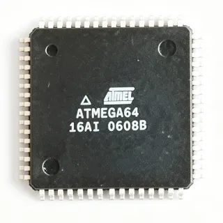
ATMEGA8515L-8AI - AVR 8-Bit MCU, 8KB Flash, 8MHz | Microchip
MPN: ATMEGA8515L-8AI ✓ Hoạt độngATMEGA8515L-8AI Tóm tắt
A microcontroller is a single-chip computer that integrates a processor core, memory, and programmable peripherals into one package, sitting at the heart of embedded systems in the broader hierarchy of semiconductors -> integrated circuits -> microcontrollers. The AVR architecture executes most of its 130 powerful instructions in a single clock cycle, so the ATmega8515L achieves up to 8 MIPS throughput at 8 MHz - roughly 1 MIPS per MHz - making it far more efficient per clock than many CISC 8-bit designs.
Key features include self-programming Flash for field firmware updates, a full-duplex USART, SPI serial interface, one 16-bit and two 8-bit timers with PWM capability, an 8-channel 10-bit ADC replacement via external memory-mapped peripherals, and 35 programmable I/O lines. The external memory bus with address latching control distinguishes this family from smaller ATmega parts such as the ATmega8.
Architecturally, the ATmega8515 is a low-power CMOS device based on the AVR enhanced RISC core with 32 general-purpose working registers directly connected to the ALU, fully static operation down to DC, and a Harvard bus structure separating program and data paths.
Typical applications include industrial control panels, legacy AVR system maintenance and re-manufacturing, motor control interfaces, and external-memory expansion designs where the 64 KB SRAM bus is essential.
For design, note the 'L' suffix limits clocking to 8 MHz - never substitute a 16 MHz grade part in a timing-critical firmware build without recalculating UART baud rates and timer constants.
This page adds distributor stock data, pin-compatible ATmega8515 family drop-in alternatives, comparison tables, and practical design notes not found in the manufacturer datasheet.
Bộ thay thế dễ dàng lắp đặt cho ATMEGA8515L-8AI — cùng gói, chân-to-chân tương thích. Các bộ phận yêu cầu hàn PCB bị loại trừ.
Các biến thể trong loạt này
Các mẫu cùng loạt có thể lắp đặt dễ dàng tương thích với ATMEGA8515L-8AI (cùng hình factor và footprint) — khác nhau ở Package, Throughput, Instructions, Operating Temperature, General Purpose I/O.
ATMEGA8515L-8AU
✅ Drop-In📋 Tham chiếu thay thế (không có trong danh mục)
ATMEGA8515-16AUR
✅ Drop-InLiên hệ để biết giá
Xem tài liệu →ATMEGA8515-16JI
✅ Drop-InLiên hệ để biết giá
Xem tài liệu →ATMEGA8515-16AI
✅ Drop-In ⚠️ Thông số chưa được xác minhLiên hệ để biết giá
Xem tài liệu →AT90S8515-8AI
✅ Drop-In📋 Tham chiếu thay thế (không có trong danh mục)
ATMEGA8515L-8AI Tỷ lệ tối đa & tính chất điện
| Core Architecture | 8-bit AVR RISC |
| Program Memory (Flash) | 8 KB (4K x 16) In-System Programmable |
| SRAM | 544 bytes internal |
| External SRAM Support | up to 64 KB |
| EEPROM | 512 bytes |
| Tần số xung maksimum | 8 MHz |
| Throughput | up to 8 MIPS at 8 MHz (16 MIPS at 16 MHz for 16 MHz grades) |
| Operating Voltage Range | 2.7 V to 5.5 V |
| Nhiệt độ hoạt động | -40C to +85C (industrial) |
| Instructions | 130 powerful instructions, most single-cycle |
| General Purpose I/O | 35 programmable I/O lines |
| Timers/Counters | 2 x 8-bit, 1 x 16-bit with PWM |
| Serial Interfaces | USART, SPI |
| Hộp | 44-TQFP (10 x 10 mm) |
| Kiểu lắp đặt | Surface Mount |
| Trạng thái RoHS | RoHS compliant (lead-free 'I' suffix per Microchip nomenclature) |
| In-Circuit Programming | ICSP via SPI (supported by MPLAB SNAP / AVR programmers) |
Hướng dẫn cấu hình chân ATMEGA8515L-8AI 44-tqfp (10 x 10 mm)
Cấu hình chân cho ATMEGA8515L-8AI (44-tqfp (10 x 10 mm) gói). IC số này bao gồm chân GPIO, giao diện truyền thông (UART, SPI, I2C) và chân nguồn. Tham khảo tài liệu thông số kỹ thuật của nhà sản xuất để biết các chức năng chân thay thế và tùy chọn cấu hình. Cực kỳ quan trọng cho thiết kế hệ thống tích hợp và lập trình PCB.

Không có dữ liệu chân cụ thể sẵn có cho ATMEGA8515L-8AI.
Tham khảo: tài liệu kỹ thuật cho cấu hình chân đầy đủ.
Ứng dụng tiêu biểu
ATMEGA8515L-8AI phù hợp cho 6 Áp dụngs: Industrial Control Panels, Legacy AVR System Maintenance, External Memory Expansion Designs, Serial Communication Gateways, Timer and PWM-Based Motion Interfaces, Embedded Instrumentation and Test Fixtures.
Industrial Control Panels
The ATMEGA8515L-8AI fits industrial control panel designs where a 5 V or 3.3 V logic environment, wide -40C to +85C temperature rating, and 35 programmable I/O lines drive relays, contactors, and status indicators. Its 2.7 V to 5.5 V supply tolerance absorbs industrial rail sag, while the USART links to HMI displays and the SPI bus to ADCs or EEPROM. The 64 KB external memory interface supports event log buffers in external SRAM, and the 512 B EEPROM retains calibration and configuration data through power cycles without external non-volatile components.
Được đề xuất
Legacy AVR System Maintenance
Many installed AVR-based products from the 2000s were built around the ATmega8515, and the ATMEGA8515L-8AI is the correct re-stocking part for repair and re-manufacturing lines. It preserves the exact 44-TQFP footprint, register map, and 8 MHz L-grade timing, so existing firmware binaries program without recompilation. The In-System Programmable Flash allows field firmware updates via the SPI ICSP interface using tools such as MPLAB SNAP. Compared with switching to a modern ATmega, this part eliminates PCB respins and requalification for service-stock and obsolescence-management programs.
Được đề xuất
External Memory Expansion Designs
The external memory bus is the ATmega8515's signature capability: ports A and C form a multiplexed data/address bus with ALE, RD, and WR strobes, addressing up to 64 KB of external SRAM. The ATMEGA8515L-8AI suits data-acquisition buffers, protocol analyzers, and dataloggers needing far more than its 544 bytes of internal SRAM. Designers latch the low address byte with a 74HC573-class latch and select wait states via XMEM control bits for slower memories. At 8 MHz, bus cycles stay comfortably within standard SRAM access times, and firmware can place stacks or frame buffers in external space transparently.
Được đề xuất
Serial Communication Gateways
With a full-duplex USART and hardware SPI, the ATMEGA8515L-8AI implements protocol converters between RS-232/RS-485 field devices and SPI peripherals such as EEPROMs, ADCs, and displays. Running at 8 MHz, the USART supports standard baud rates up to 115.2 kbps (UBRR = 8 at 115.2 kbps yields a low error percentage with U2X disabled). The 5 V tolerant industrial I/O drives RS-485 transceivers directly, and the 512 B EEPROM stores node addresses and configuration. Its 130 single-cycle instructions give headroom for CRC computation in interrupt-driven serial service routines.
Được đề xuất
Timer and PWM-Based Motion Interfaces
The ATMEGA8515L-8AI provides two 8-bit and one 16-bit timers with compare and PWM modes, suitable for stepper-drive indexing, DC motor speed commands, and servo pulse generation in industrial automation sub-systems. The 16-bit timer at 8 MHz with 1024 prescale yields ~128 us resolution for millisecond-class servo frames, while 8-bit timers generate fast PWM carrier signals for driver stages. Compared with software-only timing on slower 8051-class parts, the AVR's single-cycle ALU keeps ISR jitter low. The 35 I/O lines handle limit switches, encoder inputs, and enable signals without port expanders.
Được đề xuất
Embedded Instrumentation and Test Fixtures
Production test fixtures and bench instruments benefit from the ATMEGA8515L-8AI's deterministic single-cycle instruction timing, SPI control of ADC/DAC devices, and EEPROM-stored calibration constants. The 2.7 V to 5.5 V range allows direct integration into both 3.3 V USB-based fixtures and 5 V rack systems. Self-programming Flash supports firmware self-update in the field, while the ICSP interface permits re-flashing between test revisions without removing the 44-TQFP from the board. The external SRAM interface captures waveform or measurement datasets of up to 64 KB that a purely internal-memory MCU could not hold.
Được đề xuất
Tóm tắt các sản phẩm được đề xuất
Dữ liệu tham khảo kỹ thuật cho ATMEGA8515L-8AI — so sánh, hướng dẫn thiết kế và thông tin tuân thủ.
Hướng dẫn chọn lựa
So sánh với các sản phẩm thay thế
| Tham số | Sản phẩm này | ATMEGA8515L-8AU | ATMEGA8515-16AUR | ATMEGA8515-16JI | AT90S8515-8AI |
|---|---|---|---|---|---|
| Package | 44-TQFP (10x10 mm) | 44-TQFP (10x10 mm) - same | 44-TQFP (10x10 mm) - same | 44-TQFP (10x10 mm) - same | 44-TQFP (10x10 mm) - same |
| Brand | Microchip Technology (Atmel) | Microchip Technology (Atmel) | Microchip Technology (Atmel) | Microchip Technology (Atmel) | Microchip Technology (Atmel) |
| Flash | 8 KB ISP | 8 KB ISP | 8 KB ISP | 8 KB ISP | 8 KB (non-self-programming on AT90S) |
| Max Clock | 8 MHz | 8 MHz | 16 MHz | 16 MHz | 8 MHz |
| Operating Voltage | 2.7 V to 5.5 V | 2.7 V to 5.5 V | 4.5 V to 5.5 V | 4.5 V to 5.5 V | 4.0 V to 5.5 V |
| SRAM / External SRAM | 544 B / up to 64 KB | 544 B / up to 64 KB | 544 B / up to 64 KB | 544 B / up to 64 KB | 512 B internal / external supported |
| Temperature Range | -40C to +85C | -40C to +85C | -40C to +85C | -40C to +85C | -40C to +85C |
| Self-Programming Flash | Yes (bootloader capable) | Yes | Yes | Yes | No - key ATmega upgrade advantage |
Bảo phân biệt quan trọng
- Wider supply range with low-voltage operation (vsATMEGA8515-16AUR)
- Self-programming Flash enables field bootloaders (vsAT90S8515-8AI)
- External SRAM interface up to 64 KB (vsATMEGA8-16PI)
Ghi chú thiết kế
Decouple VCC and AVCC with 100 nF ceramic capacitors placed within 5 mm of the corresponding pins, plus a 4.7-10 uF bulk capacitor near the supply entry. Because the L grade runs from 2.7 V to 5.5 V, verify brown-out detector fuse settings (BODEN/BODLEVEL) match your minimum rail: enable BOD at 2.7 V-class thresholds for 3.3 V systems and the 4.0 V-class threshold for 5 V systems to prevent EEPROM corruption during slow power-down. Estimated: at 8 MHz and 5 V, active supply current is on the order of 10-15 mA per datasheet typical curves - size your regulator accordingly.
Never clock the ATMEGA8515L-8AI above 8 MHz - it is an L-grade die and the -16AUR is not a timing substitute at higher F_CPU. When swapping a 5 V 16 MHz part for this L grade, recompute USART UBRR values (at 8 MHz, 115200 baud requires U2X or accepts ~2% error with U2X off - verify frame-error budgets) and re-time delay loops written in cycle counts. Also, if your design uses the external memory interface, ensure the 74HC573-class address latch propagation plus SRAM access time fits within the 8 MHz bus cycle, or enable XMEM wait states.
On the 44-TQFP 10x10 mm footprint, keep the XTAL1/XTAL2 crystal traces short (under 20 mm) with ground guard, and route the SPI ICSP header directly from MOSI/MISO/SCK/RESET with series 100 ohm resistors optional for probe protection. The RESET line needs a 10 kOhm pull-up for reliable ICSP; do not add large capacitors on RESET, as they prevent programmers from entering programming mode. Ports A and C carry the external memory bus - keep stub lengths short and terminate long bus runs with series resistors to limit ringing at 8 MHz edge rates.
Thông tin tuân thủ
RoHS/lead-free status per Microchip 'I' suffix nomenclature and distributor listings; REACH and halogen-free status not stated in provided data.