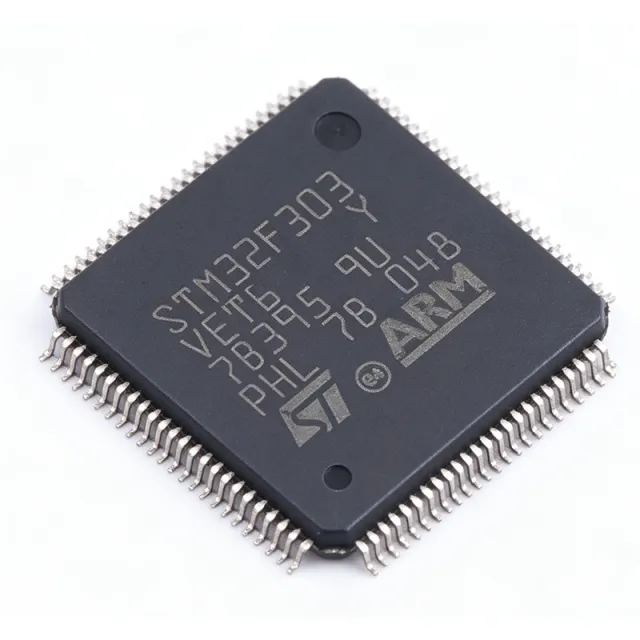
STM32F303VET6 - 512KB Flash, 72MHz ARM Cortex-M4F MCU | STMicroelectronics
MPN: STM32F303VET6 ✓ Hoạt độngSTM32F303VET6 Tóm tắt
What is an ARM Cortex-M4F microcontroller? It is a 32-bit processor core designed for embedded applications that require a balance of performance, power efficiency, and advanced digital signal processing (DSP) capabilities. The 'F' suffix indicates the presence of a hardware floating-point unit (FPU), which accelerates single-precision floating-point arithmetic, essential for control loops, audio processing, and sensor fusion. In the system hierarchy, the STM32F303VET6 sits at the application processor level, integrating the CPU, memory, peripherals, and I/O on a single chip, reducing system cost and board space.
Key features of the STM32F303VET6 include a 72 MHz ARM Cortex-M4F core with FPU, 512 KB flash, 80 KB SRAM, and a rich set of peripherals: two advanced 12-bit ADCs (up to 5 MSPS), three 12-bit DACs, seven comparators, four operational amplifiers, and a 12-channel DMA controller. It also integrates multiple communication interfaces: USART, SPI, I2C, CAN, USB, and SDIO. The device supports a supply voltage range of 2.0V to 3.6V and operates over a temperature range of -40°C to +85°C (industrial grade).
The STM32F303VET6 is built on ST's advanced 90nm process technology, offering a good balance of performance and power consumption. The Cortex-M4F core with FPU and DSP instructions enables efficient execution of complex algorithms, such as PID control, FFT, and digital filtering. The device also features a memory protection unit (MPU) and a nested vectored interrupt controller (NVIC) for robust real-time operation.
Typical applications include industrial motor control, power conversion, digital power supplies, three-phase inverters, medical devices, and audio processing. The high-speed ADCs and comparators make it ideal for fast closed-loop control systems, while the FPU accelerates mathematical computations. The device is also well-suited for IoT edge nodes that require local signal processing.
When designing with the STM32F303VET6, ensure proper decoupling of the VDD and VDDA pins with 100nF and 4.7uF capacitors, and connect the VCAP pins to ground with 2.2uF capacitors for internal regulator stability. The BOOT0 pin configuration determines the boot source; a 10k pull-down resistor is recommended for normal flash boot. For high-speed ADC applications, use a low-impedance analog supply and reference to minimize noise.
Bộ thay thế dễ dàng lắp đặt cho STM32F303VET6 — cùng gói, chân-to-chân tương thích. Các bộ phận yêu cầu hàn PCB bị loại trừ.
Các biến thể trong loạt này
Các mẫu cùng loạt có thể lắp đặt dễ dàng tương thích với STM32F303VET6 (cùng hình factor và footprint) — khác nhau ở Package, Flash Memory, SRAM, ADC, DAC.
STM32F303VCT6
📋 Tham chiếu thay thế (không có trong danh mục)
STM32F303VET7
📋 Tham chiếu thay thế (không có trong danh mục)
STM32F303VBT6
📋 Tham chiếu thay thế (không có trong danh mục)
STM32F303VET6TR
📋 Tham chiếu thay thế (không có trong danh mục)
STM32F303VCT6
📋 Tham chiếu thay thế (không có trong danh mục)
STM32F303VET7
📋 Tham chiếu thay thế (không có trong danh mục)
STM32F303VBT6
📋 Tham chiếu thay thế (không có trong danh mục)
STM32F303VET6TR
📋 Tham chiếu thay thế (không có trong danh mục)
STM32F303VCT6
📋 Tham chiếu thay thế (không có trong danh mục)
STM32F303VET7
📋 Tham chiếu thay thế (không có trong danh mục)
STM32F303VBT6
📋 Tham chiếu thay thế (không có trong danh mục)
STM32F303VET6TR
📋 Tham chiếu thay thế (không có trong danh mục)
STM32F303VCT6
📋 Tham chiếu thay thế (không có trong danh mục)
STM32F303VET7
📋 Tham chiếu thay thế (không có trong danh mục)
STM32F303VBT6
📋 Tham chiếu thay thế (không có trong danh mục)
STM32F303VET6TR
📋 Tham chiếu thay thế (không có trong danh mục)
STM32F303VCT6
📋 Tham chiếu thay thế (không có trong danh mục)
STM32F303VET7
📋 Tham chiếu thay thế (không có trong danh mục)
STM32F303VBT6
📋 Tham chiếu thay thế (không có trong danh mục)
STM32F303VET6 Tỷ lệ tối đa & tính chất điện
| Core | ARM Cortex-M4F with FPU |
| Maximum Clock Speed | 72 MHz |
| Flash Memory | 512 KB |
| SRAM | 80 KB |
| Supply Voltage Range | 2.0 V to 3.6 V |
| Khoảng nhiệt độ hoạt động | -40°C to +85°C |
| Hộp | LQFP100 (14x14 mm, 0.5 mm pitch) |
| Number of I/O Pins | 87 |
| ADC Resolution | 12-bit |
| ADC Sample Rate | 5 MSPS |
| DAC Resolution | 12-bit |
| Number of Comparators | 7 |
| Number of Operational Amplifiers | 4 |
| DMA Channels | 12 |
| Communication Interfaces | USART, SPI, I2C, CAN, USB, SDIO |
| Trạng thái RoHS | Compliant |
Cấu hình chân STM32F303VET6
| Chân 1 | PE2 — GPIO / alternate function |
| Chân 2 | PE3 — GPIO / alternate function |
| Chân 3 | PE4 — GPIO / alternate function |
| Chân 4 | PE5 — GPIO / alternate function |
| Chân 5 | PE6 — GPIO / alternate function |
| Chân 6 | VBAT — Battery backup supply |
| Chân 7 | PC13 — GPIO / RTC / tamper |
| Chân 8 | PC14 — GPIO / OSC32_IN |
| Chân 9 | PC15 — GPIO / OSC32_OUT |
| Chân 10 | PF0 — GPIO / OSC_IN |
| Chân 11 | PF1 — GPIO / OSC_OUT |
| Chân 12 | NRST — Reset (active low) |
| Chân 13 | PC0 — GPIO / ADC input |
| Chân 14 | PC1 — GPIO / ADC input |
| Chân 15 | PC2 — GPIO / ADC input |
| Chân 16 | PC3 — GPIO / ADC input |
| Chân 17 | VSSA — Analog ground |
| Chân 18 | VDDA — Analog power supply |
| Chân 19 | PA0 — GPIO / ADC / WKUP |
| Chân 20 | PA1 — GPIO / ADC |
| Chân 21 | PA2 — GPIO / USART2_TX |
| Chân 22 | PA3 — GPIO / USART2_RX |
| Chân 23 | PA4 — GPIO / DAC_OUT1 |
| Chân 24 | PA5 — GPIO / DAC_OUT2 |
| Chân 25 | PA6 — GPIO / TIM3_CH1 |
| Chân 26 | PA7 — GPIO / TIM3_CH2 |
| Chân 27 | PC4 — GPIO / ADC input |
| Chân 28 | PC5 — GPIO / ADC input |
| Chân 29 | PB0 — GPIO / TIM3_CH3 |
| Chân 30 | PB1 — GPIO / TIM3_CH4 |
| Chân 31 | PB2 — GPIO / BOOT1 |
| Chân 32 | PE7 — GPIO / TIM1_ETR |
| Chân 33 | PE8 — GPIO / TIM1_CH1N |
| Chân 34 | PE9 — GPIO / TIM1_CH1 |
| Chân 35 | PE10 — GPIO / TIM1_CH2N |
| Chân 36 | PE11 — GPIO / TIM1_CH2 |
| Chân 37 | PE12 — GPIO / TIM1_CH3N |
| Chân 38 | PE13 — GPIO / TIM1_CH3 |
| Chân 39 | PE14 — GPIO / TIM1_CH4 |
| Chân 40 | PE15 — GPIO / TIM1_CH4N |
| Chân 41 | PB10 — GPIO / I2C2_SCL |
| Chân 42 | PB11 — GPIO / I2C2_SDA |
| Chân 43 | VSS_1 — Ground |
| Chân 44 | VDD_1 — Power supply |
| Chân 45 | PB12 — GPIO / SPI2_NSS |
| Chân 46 | PB13 — GPIO / SPI2_SCK |
| Chân 47 | PB14 — GPIO / SPI2_MISO |
| Chân 48 | PB15 — GPIO / SPI2_MOSI |
| Chân 49 | PD8 — GPIO / USART3_TX |
| Chân 50 | PD9 — GPIO / USART3_RX |
| Chân 51 | PD10 — GPIO / USART3_CK |
| Chân 52 | PD11 — GPIO / USART3_CTS |
| Chân 53 | PD12 — GPIO / USART3_RTS |
| Chân 54 | PD13 — GPIO / TIM4_CH2 |
| Chân 55 | PD14 — GPIO / TIM4_CH3 |
| Chân 56 | PD15 — GPIO / TIM4_CH4 |
| Chân 57 | PC6 — GPIO / TIM8_CH1 |
| Chân 58 | PC7 — GPIO / TIM8_CH2 |
| Chân 59 | PC8 — GPIO / TIM8_CH3 |
| Chân 60 | PC9 — GPIO / TIM8_CH4 |
| Chân 61 | PA8 — GPIO / TIM1_CH1 |
| Chân 62 | PA9 — GPIO / USART1_TX |
| Chân 63 | PA10 — GPIO / USART1_RX |
| Chân 64 | PA11 — GPIO / USB_DM |
| Chân 65 | PA12 — GPIO / USB_DP |
| Chân 66 | PA13 — GPIO / SWDIO |
| Chân 67 | VSS_2 — Ground |
| Chân 68 | VDD_2 — Power supply |
| Chân 69 | PA14 — GPIO / SWCLK |
| Chân 70 | PA15 — GPIO / JTDI |
| Chân 71 | PC10 — GPIO / USART4_TX |
| Chân 72 | PC11 — GPIO / USART4_RX |
| Chân 73 | PC12 — GPIO / USART5_TX |
| Chân 74 | PD0 — GPIO / CAN1_RX |
| Chân 75 | PD1 — GPIO / CAN1_TX |
| Chân 76 | PD2 — GPIO / SDIO_CMD |
| Chân 77 | PD3 — GPIO / SDIO_CLK |
| Chân 78 | PD4 — GPIO / SDIO_D0 |
| Chân 79 | PD5 — GPIO / SDIO_D1 |
| Chân 80 | PD6 — GPIO / SDIO_D2 |
| Chân 81 | PD7 — GPIO / SDIO_D3 |
| Chân 82 | PB3 — GPIO / JTDO |
| Chân 83 | PB4 — GPIO / NJTRST |
| Chân 84 | PB5 — GPIO / I2C1_SMBA |
| Chân 85 | PB6 — GPIO / I2C1_SCL |
| Chân 86 | PB7 — GPIO / I2C1_SDA |
| Chân 87 | BOOT0 — Boot mode selection |
| Chân 88 | PB8 — GPIO / CAN2_RX |
| Chân 89 | PB9 — GPIO / CAN2_TX |
| Chân 90 | PE0 — GPIO / TIM4_ETR |
| Chân 91 | PE1 — GPIO / TIM4_CH1 |
| Chân 92 | VSS_3 — Ground |
| Chân 93 | VDD_3 — Power supply |
| Chân 94 | PB0 — GPIO / TIM3_CH3 |
| Chân 95 | PB1 — GPIO / TIM3_CH4 |
| Chân 96 | PB2 — GPIO / BOOT1 |
| Chân 97 | PE7 — GPIO / TIM1_ETR |
| Chân 98 | PE8 — GPIO / TIM1_CH1N |
| Chân 99 | PE9 — GPIO / TIM1_CH1 |
| Chân 100 | PE10 — GPIO / TIM1_CH2N |
Ứng dụng tiêu biểu
STM32F303VET6 phù hợp cho 6 Áp dụngs: Industrial Motor Control, Digital Power Conversion, Medical Devices, Audio Processing, IoT Edge Nodes, Robotics.
Industrial Motor Control
The STM32F303VET6 is ideal for industrial motor control due to its high-speed ADCs (5 MSPS), comparators, and advanced timers with dead-time generation. It supports field-oriented control (FOC) for BLDC and PMSM motors, enabling efficient and precise speed and torque control. The FPU accelerates the mathematical computations required for real-time control loops, such as Clarke and Park transforms. In a typical application, the MCU reads phase currents via the ADCs, processes them with the FPU, and generates PWM signals to drive the inverter. The built-in comparators provide overcurrent protection, and the timers generate complementary PWM with programmable dead-time to prevent shoot-through. Compared to using a separate DSP, the STM32F303VET6 integrates all necessary peripherals, reducing BOM cost and board space. Designers should ensure proper isolation between the power stage and the MCU, and use the ADC sampling synchronization feature to minimize current measurement noise.
Được đề xuất
Digital Power Conversion
The STM32F303VET6 excels in digital power conversion, such as switch-mode power supplies (SMPS) and DC-DC converters. Its high-speed ADCs (up to 5 MSPS) enable fast voltage and current sensing, while the advanced timers generate high-resolution PWM signals. The FPU accelerates the digital control loop algorithms, such as PID or state-space controllers, allowing high bandwidth and stability. In a typical application, the MCU samples the output voltage and inductor current, computes the duty cycle, and updates the PWM in real-time. The comparators can be used for cycle-by-cycle current limiting, and the DACs can provide reference voltages for analog comparators. The device's 72 MHz clock and 12 DMA channels ensure low-latency data transfer. Compared to analog controllers, the digital approach offers flexibility, programmability, and better transient response. Designers should pay attention to the ADC sampling timing and use the synchronization feature to avoid aliasing.
Được đề xuất
Medical Devices
The STM32F303VET6 is suitable for medical devices such as patient monitors, infusion pumps, and diagnostic equipment. Its high-speed ADCs and op-amps enable precise sensor signal conditioning, while the FPU handles complex algorithms like digital filtering and signal analysis. The device's low power consumption and wide supply voltage range (2.0V to 3.6V) support battery-powered portable devices. In a typical application, the MCU reads vital signs from sensors (e.g., ECG, SpO2), processes the signals to extract meaningful data, and communicates via USB or UART to a display or central station. The built-in comparators can be used for alarm generation. The device's industrial temperature range (-40°C to +85°C) ensures reliability in clinical environments. Designers must follow medical safety standards (e.g., IEC 60601) and ensure proper isolation and EMC protection.
Được đề xuất
Audio Processing
The STM32F303VET6 is well-suited for audio processing applications, such as audio effects processors, active noise cancellation, and voice recognition. The Cortex-M4F core with FPU and DSP instructions accelerates FFT, filtering, and audio codec algorithms. The device's high-speed ADCs and DACs (12-bit) can interface directly with audio codecs or analog audio signals. In a typical application, the MCU samples audio input via the ADC, processes it (e.g., equalization, echo cancellation), and outputs via the DAC. The DMA controller enables efficient data transfer without CPU intervention. The device's 72 MHz clock provides sufficient processing power for real-time audio effects. Compared to using a dedicated DSP, the STM32F303VET6 offers a cost-effective solution with integrated peripherals. Designers should use high-quality audio codecs and ensure proper grounding to minimize noise.
Được đề xuất
IoT Edge Nodes
The STM32F303VET6 can serve as the main controller in IoT edge nodes, handling sensor data acquisition, local processing, and communication. Its rich set of communication interfaces (USART, SPI, I2C, CAN, USB, SDIO) allows connection to various sensors and wireless modules. The FPU enables on-device signal processing, reducing the need to send raw data to the cloud. In a typical application, the MCU reads environmental sensors (temperature, humidity, gas), processes the data to detect anomalies, and sends alerts via Wi-Fi or LoRa. The device's low power modes (sleep, stop, standby) help extend battery life. The 512 KB flash provides ample space for firmware and data logging. Designers should optimize power consumption by using the low-power modes and disabling unused peripherals.
Được đề xuất
Robotics
The STM32F303VET6 is ideal for robotics applications, including robotic arms, drones, and autonomous vehicles. Its high-speed ADCs and timers enable precise motor control, while the FPU handles kinematics and trajectory planning. The device's multiple communication interfaces allow interfacing with sensors (IMU, encoders) and actuators. In a typical application, the MCU reads joint angles from encoders, computes the inverse kinematics, and generates PWM signals for servo motors. The built-in comparators provide overcurrent protection. The device's 72 MHz clock and 12 DMA channels ensure real-time performance. Compared to using a Raspberry Pi, the STM32F303VET6 offers deterministic timing and lower power consumption, making it suitable for real-time control. Designers should implement safety features such as emergency stop and limit switches.
Được đề xuất
Tóm tắt các sản phẩm được đề xuất
Dữ liệu tham khảo kỹ thuật cho STM32F303VET6 — so sánh, hướng dẫn thiết kế và thông tin tuân thủ.
Hướng dẫn chọn lựa
So sánh với các sản phẩm thay thế
| Tham số | Sản phẩm này | STM32F303VCT6 | STM32F303VET7 | STM32F303VBT6 |
|---|---|---|---|---|
| Package | LQFP100 | LQFP100 | LQFP100 | LQFP100 |
| Brand | STMicroelectronics | STMicroelectronics | STMicroelectronics | STMicroelectronics |
| Core | ARM Cortex-M4F | ARM Cortex-M4F | ARM Cortex-M4F | ARM Cortex-M4F |
| Maximum Clock Speed | 72 MHz | 72 MHz | 72 MHz | 72 MHz |
| Flash Memory | 512 KB | 256 KB | 512 KB | 128 KB |
| SRAM | 80 KB | 40 KB | 80 KB | 32 KB |
| ADC Sample Rate | 5 MSPS | 5 MSPS | 5 MSPS | 5 MSPS |
| Operating Temperature Range | -40°C to +85°C | -40°C to +85°C | -40°C to +105°C | -40°C to +85°C |
Bảo phân biệt quan trọng
- High-speed ADCs (5 MSPS) with simultaneous sampling (vsSTM32F103VET6)
- Integrated operational amplifiers and comparators (vsSTM32F407VET6)
- Floating-point unit (FPU) for DSP (vsSTM32F103VET6)
Ghi chú thiết kế
The STM32F303VET6 requires a stable power supply. Connect a 100nF ceramic capacitor and a 4.7uF tantalum capacitor to each VDD pin, and a 1uF capacitor to VDDA. The VCAP pins (VCAP1 and VCAP2) must be connected to ground with 2.2uF capacitors for the internal voltage regulator. Ensure the power supply can handle the peak current during flash programming and high-speed operation.
For optimal ADC performance, keep the analog supply (VDDA) and reference (VREF+) separate from the digital supply, and use a star-point grounding scheme. Place decoupling capacitors close to the pins, and avoid routing high-speed digital traces near the analog input pins. Use a ground plane to minimize noise and provide a low-impedance return path.
A common mistake is forgetting to connect the BOOT0 pin correctly. For normal flash boot, BOOT0 must be tied low (through a 10k resistor to ground). Also, ensure the NRST pin has a 100nF capacitor to ground for reliable reset. When using the SWD interface, connect SWDIO and SWCLK with pull-up/pull-down resistors as recommended in the datasheet to avoid debug connection issues.
Thông tin tuân thủ
RoHS compliant per STMicroelectronics product page. Not AEC-Q100 qualified (industrial grade).
