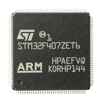
STM32F207ZGT6 - 32-bit ARM Cortex-M3 MCU, 1MB Flash | STMicroelectronics
MPN: STM32F207ZGT6 ✓ 啟用中STM32F207ZGT6 概覽
A microcontroller (MCU) is a compact integrated circuit designed to govern a specific operation in an embedded system. It contains a processor core, memory (Flash and SRAM), and programmable input/output peripherals. The STM32F207ZGT6 belongs to the STM32F2 series, which is part of the broader STM32 family of 32-bit Flash microcontrollers. This family is widely used in industrial control, consumer electronics, and IoT devices due to its balance of performance, power efficiency, and peripheral integration.
Key features of the STM32F207ZGT6 include a 120 MHz ARM Cortex-M3 core with 1.25 DMIPS/MHz, 1 MB of Flash memory, 128 KB of SRAM, and a comprehensive set of peripherals: 3x 12-bit ADCs, 2x DACs, 4x USARTs, 2x UARTs, 3x SPI, 2x I2C, 2x CAN, 1x USB 2.0 OTG FS/HS, 1x Ethernet MAC, and a camera interface. It also features a flexible memory controller (FMC) for external memory expansion, a true random number generator (RNG), and a cryptographic acceleration cell for AES, DES, and 3DES.
The STM32F207ZGT6 is built on a 90nm process technology, offering a good balance between performance and power consumption. It operates from a 1.8V to 3.6V power supply and supports a wide temperature range of -40°C to +85°C. The device includes multiple low-power modes (Sleep, Stop, Standby) to optimize energy consumption in battery-powered applications.
Typical applications include industrial automation, motor control, medical devices, point-of-sale terminals, and IoT gateways. The Ethernet MAC and USB OTG support enable connectivity in networked systems, while the rich analog peripherals suit data acquisition and control loops.
When designing with this MCU, ensure proper decoupling of the power supply pins and a stable clock source. The device supports external crystal oscillators (4-26 MHz) and an internal 16 MHz RC oscillator. For high-speed USB and Ethernet, an external 25 MHz crystal is recommended. The boot pins must be configured correctly for programming via USART or USB.
直接替換替代品,適用於 STM32F207ZGT6 — 相同封裝,腳位對腳位相容。需重新設計 PCB 的不同封裝零件不列入。
此系列的變體
與下列產品可直接替換的同系列型號: STM32F207ZGT6 (相同外形與佔位) — 差異在於 Ethernet, Flash Memory, Operating Temperature, Supply Voltage.
STM32F207ZGT6
✅ 直接替換聯絡詢價
查看資料表 →STM32F207ZGT6TR
✅ 直接替換📋 參考替代品(不在目錄中)
STM32F207ZGT6
✅ 直接替換聯絡詢價
查看資料表 →STM32F207ZGT6
✅ 直接替換聯絡詢價
查看資料表 →STM32F207ZGT6
✅ 直接替換聯絡詢價
查看資料表 →STM32F207ZGT6
✅ 直接替換聯絡詢價
查看資料表 →STM32F207ZGT6
✅ 直接替換聯絡詢價
查看資料表 →STM32F207ZGT6
✅ 直接替換聯絡詢價
查看資料表 →STM32F207ZGT6
✅ 直接替換聯絡詢價
查看資料表 →STM32F207ZGT6
✅ 直接替換聯絡詢價
查看資料表 →STM32F207ZGT6
✅ 直接替換聯絡詢價
查看資料表 →STM32F207ZGT6
✅ 直接替換聯絡詢價
查看資料表 →STM32F207ZGT6
✅ 直接替換聯絡詢價
查看資料表 →STM32F207ZGT6
✅ 直接替換聯絡詢價
查看資料表 →STM32F207ZGT6
✅ 直接替換聯絡詢價
查看資料表 →STM32F207ZGT6
✅ 直接替換聯絡詢價
查看資料表 →STM32F207ZGT6
✅ 直接替換聯絡詢價
查看資料表 →STM32F207ZGT6
✅ 直接替換聯絡詢價
查看資料表 →STM32F207ZGT6
✅ 直接替換聯絡詢價
查看資料表 →STM32F207ZGT6
✅ 直接替換聯絡詢價
查看資料表 →STM32F207ZGT6 最大額定值與電氣特性
| Core | ARM Cortex-M3 |
| Max Clock Frequency | 120 MHz |
| Flash Memory | 1 MB |
| SRAM | 128 KB |
| 供應電壓 | 1.8 V to 3.6 V |
| 工作溫度 | -40C to +85C |
| 封裝 | LQFP144 (20x20 mm) |
| Number of I/O Pins | 114 |
| ADC | 3x 12-bit, up to 24 channels |
| DAC | 2x 12-bit |
| USART/UART | 4x USART, 2x UART |
| SPI | 3x SPI |
| I2C | 2x I2C |
| CAN | 2x CAN 2.0B |
| USB | USB 2.0 OTG FS/HS |
| Ethernet | 10/100 Ethernet MAC |
| Timers | 12x 16-bit, 2x 32-bit |
| DMA | 16-channel DMA |
| RTC | Yes |
| RoHS | Compliant |
STM32F207ZGT6 腳位配置
| 腳位 1 | PE2 — GPIO or alternate function |
| 腳位 2 | PE3 — GPIO or alternate function |
| 腳位 3 | PE4 — GPIO or alternate function |
| 腳位 4 | PE5 — GPIO or alternate function |
| 腳位 5 | PE6 — GPIO or alternate function |
| 腳位 6 | VBAT — Battery backup supply |
| 腳位 7 | PC13 — GPIO or RTC output |
| 腳位 8 | PC14 — GPIO or OSC32_IN |
| 腳位 9 | PC15 — GPIO or OSC32_OUT |
| 腳位 10 | PF0 — GPIO or OSC_IN |
| 腳位 11 | PF1 — GPIO or OSC_OUT |
| 腳位 12 | PF2 — GPIO |
| 腳位 13 | PF3 — GPIO |
| 腳位 14 | PF4 — GPIO |
| 腳位 15 | PF5 — GPIO |
| 腳位 16 | PF6 — GPIO |
| 腳位 17 | PF7 — GPIO |
| 腳位 18 | PF8 — GPIO |
| 腳位 19 | PF9 — GPIO |
| 腳位 20 | PF10 — GPIO |
| 腳位 21 | VSS — Ground |
| 腳位 22 | VDD — Power supply |
| 腳位 23 | PF11 — GPIO |
| 腳位 24 | PF12 — GPIO |
| 腳位 25 | PF13 — GPIO |
| 腳位 26 | PF14 — GPIO |
| 腳位 27 | PF15 — GPIO |
| 腳位 28 | PG0 — GPIO |
| 腳位 29 | PG1 — GPIO |
| 腳位 30 | PG2 — GPIO |
| 腳位 31 | PG3 — GPIO |
| 腳位 32 | PG4 — GPIO |
| 腳位 33 | PG5 — GPIO |
| 腳位 34 | PG6 — GPIO |
| 腳位 35 | PG7 — GPIO |
| 腳位 36 | PG8 — GPIO |
| 腳位 37 | PG9 — GPIO |
| 腳位 38 | PG10 — GPIO |
| 腳位 39 | PG11 — GPIO |
| 腳位 40 | PG12 — GPIO |
| 腳位 41 | PG13 — GPIO |
| 腳位 42 | PG14 — GPIO |
| 腳位 43 | PG15 — GPIO |
| 腳位 44 | VSS — Ground |
| 腳位 45 | VDD — Power supply |
| 腳位 46 | PD0 — GPIO or OSC_IN |
| 腳位 47 | PD1 — GPIO or OSC_OUT |
| 腳位 48 | PD2 — GPIO |
| 腳位 49 | PD3 — GPIO |
| 腳位 50 | PD4 — GPIO |
| 腳位 51 | PD5 — GPIO |
| 腳位 52 | PD6 — GPIO |
| 腳位 53 | PD7 — GPIO |
| 腳位 54 | PD8 — GPIO |
| 腳位 55 | PD9 — GPIO |
| 腳位 56 | PD10 — GPIO |
| 腳位 57 | PD11 — GPIO |
| 腳位 58 | PD12 — GPIO |
| 腳位 59 | PD13 — GPIO |
| 腳位 60 | PD14 — GPIO |
| 腳位 61 | PD15 — GPIO |
| 腳位 62 | PC0 — GPIO or ADC input |
| 腳位 63 | PC1 — GPIO or ADC input |
| 腳位 64 | PC2 — GPIO or ADC input |
| 腳位 65 | PC3 — GPIO or ADC input |
| 腳位 66 | VSSA — Analog ground |
| 腳位 67 | VDDA — Analog power supply |
| 腳位 68 | PC4 — GPIO or ADC input |
| 腳位 69 | PC5 — GPIO or ADC input |
| 腳位 70 | PB0 — GPIO or ADC input |
| 腳位 71 | PB1 — GPIO or ADC input |
| 腳位 72 | PB2 — GPIO |
| 腳位 73 | PB3 — GPIO or JTDO |
| 腳位 74 | PB4 — GPIO or NJTRST |
| 腳位 75 | PB5 — GPIO |
| 腳位 76 | PB6 — GPIO or I2C1_SCL |
| 腳位 77 | PB7 — GPIO or I2C1_SDA |
| 腳位 78 | BOOT0 — Boot mode selection |
| 腳位 79 | PB8 — GPIO or I2C1_SCL |
| 腳位 80 | PB9 — GPIO or I2C1_SDA |
| 腳位 81 | PE0 — GPIO |
| 腳位 82 | PE1 — GPIO |
| 腳位 83 | VSS — Ground |
| 腳位 84 | VDD — Power supply |
| 腳位 85 | PE7 — GPIO |
| 腳位 86 | PE8 — GPIO |
| 腳位 87 | PE9 — GPIO |
| 腳位 88 | PE10 — GPIO |
| 腳位 89 | PE11 — GPIO |
| 腳位 90 | PE12 — GPIO |
| 腳位 91 | PE13 — GPIO |
| 腳位 92 | PE14 — GPIO |
| 腳位 93 | PE15 — GPIO |
| 腳位 94 | PB10 — GPIO or I2C2_SCL |
| 腳位 95 | PB11 — GPIO or I2C2_SDA |
| 腳位 96 | PB12 — GPIO or SPI2_NSS |
| 腳位 97 | PB13 — GPIO or SPI2_SCK |
| 腳位 98 | PB14 — GPIO or SPI2_MISO |
| 腳位 99 | PB15 — GPIO or SPI2_MOSI |
| 腳位 100 | PD8 — GPIO or USART3_TX |
| 腳位 101 | PD9 — GPIO or USART3_RX |
| 腳位 102 | PD10 — GPIO or USART3_CK |
| 腳位 103 | PD11 — GPIO or USART3_CTS |
| 腳位 104 | PD12 — GPIO or USART3_RTS |
| 腳位 105 | PD13 — GPIO |
| 腳位 106 | PD14 — GPIO |
| 腳位 107 | PD15 — GPIO |
| 腳位 108 | PC6 — GPIO or I2S2_MCK |
| 腳位 109 | PC7 — GPIO or I2S2_SCK |
| 腳位 110 | PC8 — GPIO or I2S2_SD |
| 腳位 111 | PC9 — GPIO or I2S2_WS |
| 腳位 112 | PA0 — GPIO or ADC input |
| 腳位 113 | PA1 — GPIO or ADC input |
| 腳位 114 | PA2 — GPIO or ADC input |
| 腳位 115 | PA3 — GPIO or ADC input |
| 腳位 116 | VSS — Ground |
| 腳位 117 | VDD — Power supply |
| 腳位 118 | PA4 — GPIO or DAC_OUT1 |
| 腳位 119 | PA5 — GPIO or DAC_OUT2 |
| 腳位 120 | PA6 — GPIO |
| 腳位 121 | PA7 — GPIO |
| 腳位 122 | PA8 — GPIO |
| 腳位 123 | PA9 — GPIO or USART1_TX |
| 腳位 124 | PA10 — GPIO or USART1_RX |
| 腳位 125 | PA11 — GPIO or USB_DM |
| 腳位 126 | PA12 — GPIO or USB_DP |
| 腳位 127 | PA13 — GPIO or JTMS/SWDIO |
| 腳位 128 | PA14 — GPIO or JTCK/SWCLK |
| 腳位 129 | PA15 — GPIO or JTDI |
| 腳位 130 | PC10 — GPIO |
| 腳位 131 | PC11 — GPIO |
| 腳位 132 | PC12 — GPIO |
| 腳位 133 | PD0 — GPIO or OSC_IN |
| 腳位 134 | PD1 — GPIO or OSC_OUT |
| 腳位 135 | PD2 — GPIO |
| 腳位 136 | PD3 — GPIO |
| 腳位 137 | PD4 — GPIO |
| 腳位 138 | PD5 — GPIO |
| 腳位 139 | PD6 — GPIO |
| 腳位 140 | PD7 — GPIO |
| 腳位 141 | VSS — Ground |
| 腳位 142 | VDD — Power supply |
| 腳位 143 | PB12 — GPIO or SPI2_NSS |
| 腳位 144 | PB13 — GPIO or SPI2_SCK |
典型應用
STM32F207ZGT6 適用於 6 應用s: Industrial Automation, IoT Gateway, Motor Control, Medical Devices, Point-of-Sale (POS) Terminals, Audio Processing.
Industrial Automation
The STM32F207ZGT6 is ideal for industrial automation due to its 120 MHz Cortex-M3 core, rich communication interfaces (CAN, UART, SPI, I2C), and advanced timers for PWM generation. It can handle real-time control loops, motor control, and PLC I/O modules. The device's 1 MB Flash allows storing complex control algorithms and communication stacks. Its wide operating temperature range (-40°C to +85°C) ensures reliability in harsh industrial environments. The Ethernet MAC enables connectivity to industrial networks like EtherCAT or PROFINET when paired with an external PHY. The multiple ADCs and DACs facilitate analog signal acquisition and generation for process control.
推薦
IoT Gateway
The STM32F207ZGT6 serves as a powerful IoT gateway MCU, connecting sensors and devices to the cloud. Its Ethernet MAC and USB OTG support wired and wireless connectivity (via external modules). The 1 MB Flash and 128 KB SRAM can run TCP/IP stacks (lwIP), MQTT, and TLS. The device's low-power modes help reduce energy consumption in always-on gateways. The multiple UARTs and SPI interfaces allow connection to various sensors and radio modules (e.g., Wi-Fi, LoRa). The cryptographic acceleration cell (AES, DES, 3DES) enhances security for data transmission. The RTC enables time-stamping of sensor data.
推薦
Motor Control
The STM32F207ZGT6 is well-suited for motor control applications, including BLDC, PMSM, and stepper motors. Its advanced timers (TIM1, TIM8) generate high-resolution PWM signals with dead-time insertion, essential for driving power stages. The 12-bit ADCs sample motor currents and voltages for FOC (Field-Oriented Control) algorithms. The 120 MHz core provides sufficient computational power for real-time control loops. The device's multiple communication interfaces (CAN, UART) enable integration with motor drives and industrial networks. The DMA controller offloads data transfer, reducing CPU load. The device's robust design and wide temperature range make it suitable for industrial motor drives.
推薦
Medical Devices
The STM32F207ZGT6 is used in medical devices such as patient monitors, infusion pumps, and diagnostic equipment. Its high processing power and rich analog peripherals (ADCs, DACs) enable precise signal acquisition and control. The device's 1 MB Flash allows storing complex algorithms for signal processing and user interfaces. The multiple communication interfaces (USB, UART, SPI) facilitate data transfer to host systems. The device's low-power modes are beneficial for battery-powered portable medical devices. The cryptographic acceleration cell can secure patient data. The device's reliability and long-term availability make it suitable for medical applications.
推薦
Point-of-Sale (POS) Terminals
The STM32F207ZGT6 is ideal for POS terminals, providing the processing power and connectivity needed for payment transactions. Its Ethernet MAC and USB OTG support wired and wireless connectivity to payment networks. The device's 1 MB Flash can store payment application code and encryption keys. The cryptographic acceleration cell (AES, DES, 3DES) ensures secure transactions. The multiple UARTs and SPI interfaces connect to card readers, PIN pads, and displays. The device's rich peripheral set and 114 I/O pins allow flexible system design. The wide operating temperature range ensures reliable operation in retail environments.
推薦
Audio Processing
The STM32F207ZGT6 can be used in audio processing applications such as audio interfaces, effects processors, and voice-controlled devices. Its 120 MHz Cortex-M3 core can handle audio DSP algorithms like filtering and equalization. The device's 2x 12-bit DACs can output analog audio signals, while the I2S interface (via SPI) connects to external audio codecs. The 1 MB Flash allows storing audio samples and processing code. The USB OTG supports audio streaming to/from a host. The device's low-latency interrupt handling ensures real-time audio processing. The cryptographic acceleration cell can be used for DRM protection.
推薦
推薦產品摘要
工程參考資料,適用於 STM32F207ZGT6 — 比較、設計指引及合規資訊。
選型指南
與替代品比較
| 參數 | 本產品 | STM32F207ZGT6 | STM32F407ZGT6 | STM32F205ZGT6 |
|---|---|---|---|---|
| Package | LQFP144 | LQFP144 | LQFP144 | LQFP144 |
| Brand | STMicroelectronics | STMicroelectronics | STMicroelectronics | STMicroelectronics |
| Core | ARM Cortex-M3 | ARM Cortex-M3 | ARM Cortex-M4 with FPU | ARM Cortex-M3 |
| Max Clock Frequency | 120 MHz | 120 MHz | 168 MHz | 120 MHz |
| Flash Memory | 1 MB | 1 MB | 1 MB | 1 MB |
| SRAM | 128 KB | 128 KB | 128 KB | 128 KB |
| Ethernet MAC | Yes | Yes | Yes | No |
| USB OTG | FS/HS | FS/HS | FS/HS | FS/HS |
| Price (1pc) | $12.50 | $12.50 | $14.20 | $11.80 |
主要差異化特點
- Higher clock frequency than STM32F205ZGT6 (對比STM32F205ZGT6)
- Ethernet MAC included (對比STM32F205ZGT6)
- Lower power consumption than STM32F407ZGT6 (對比STM32F407ZGT6)
設計說明
The STM32F207ZGT6 requires a stable 3.3V supply. Decouple each VDD pin with a 100nF ceramic capacitor placed as close as possible to the pin, and add a 4.7uF bulk capacitor at the power entry. The VDDA pin should be filtered with a ferrite bead and a 1uF capacitor to reduce analog noise. Ensure the VDD and VDDA voltages are within 1.8V to 3.6V range.
For high-speed USB and Ethernet, use a 25 MHz crystal with load capacitors as specified in the datasheet. Keep the crystal traces short and away from high-speed digital signals. For the LQFP144 package, ensure proper solder paste stencil design for the 0.5mm pitch pins. Use a 4-layer PCB with a solid ground plane for best EMC performance.
Do not forget to configure the boot pins (BOOT0 and BOOT1) correctly. For normal operation, BOOT0 should be tied low. When programming via USART, BOOT0 must be high. Also, ensure the NRST pin has a 100nF capacitor to ground for reliable reset. The VCAP pins (if present) require a 2.2uF capacitor to ground for internal regulator stability.
合規資訊
RoHS and REACH compliant per STMicroelectronics. Not AEC-Q100 qualified; for automotive use, consider STM32F207ZGT6Q or similar.