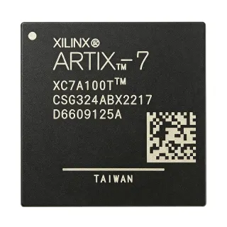
XC2C256-7FT256C - 256-Macrocell 7 ns CPLD | AMD | FTBGA
MPN: XC2C256-7FT256C ✗ 停產XC2C256-7FT256C 概覽
A complex programmable logic device, or CPLD, is a user-programmable semiconductor within the broader FPGA and programmable-logic hierarchy. Unlike a soft microcontroller core, a CPLD implements Boolean equations, counters, state machines, interfaces, and control logic directly in a non-volatile configuration fabric. This makes the XC2C256 well suited to boot-time logic, deterministic control paths, signal conditioning, protocol bridging, and fixed-function logic replacement.
The CoolRunner-II architecture provides 256 macrocells, approximately 6000 system gates, and a 7.5 ns propagation-delay grade. The device supports 184 I/O operations according to product listings, while its 256-pin FTBGA package provides the required interconnect density for a logic-dense design. Non-volatile configuration allows the programmed function to become available without an external configuration PROM after power-up.
This device belongs to the speed-grade and package family identified as XC2C256. The “-7” designation identifies the 7.5 ns performance class, while the “FT256C” portion identifies the 256-pin package and commercial temperature option. The 1.55 mm seated-height measurement and the 256-pin BGA format should be considered together when defining PCB stack-up, solder-mask and paste patterns, component placement, and board-level inspection requirements.
Typical uses include industrial control and sequencing, communications infrastructure, embedded system glue logic, programmable interface consolidation, and compact control systems requiring non-volatile configuration. In each case, the CoolRunner-II fabric can combine multiple finite-state machines and datapath elements while retaining deterministic behavior after power restoration.
PCB implementation requires particular care because the 256-pin FTBGA has a dense ball pitch and cannot be inspected visually after soldering in the same way as a leaded package. Follow AMD's package and PCB design guidance, preserve the recommended power and ground-plane arrangement, and qualify the solder-paste stencil, reflow profile, and X-ray inspection process before volume production.
This page organizes the principal device characteristics, package information, practical application guidance, and traceable replacement options around the XC2C256-7FT256C. It also distinguishes device-family alternatives from true pin-compatible drop-in choices so engineers can assess timing, package, temperature grade, and programmed-logic implications before making a design change.
直接替換替代品,適用於 XC2C256-7FT256C — 相同封裝,腳位對腳位相容。需重新設計 PCB 的不同封裝零件不列入。
XC2C256-7FT256I
✅ 直接替換聯絡詢價
查看資料表 →XC2C256-7FTG256C
✅ 直接替換📋 參考替代品(不在目錄中)
XC2C256-7FTG256I
✅ 直接替換📋 參考替代品(不在目錄中)
XC2C256-6FTG256C
✅ 直接替換📋 參考替代品(不在目錄中)
XC2C256-6FT256C
✅ 直接替換聯絡詢價
查看資料表 →XC2C256-7FT256C 最大額定值與電氣特性
| Device Type | CoolRunner-II complex programmable logic device |
| Macrocells | 256 macrocells |
| System Gates | Approximately 6000 gates |
| Propagation Delay | 7.5 ns |
| 最大時脈頻率 | 108 MHz |
| Input/Output Operations | 184 I/O operations |
| 封裝 | 256-pin FTBGA |
| Seated Height | 1.55 mm |
| Configuration Technology | Non-volatile, instant-on configuration |
| Architecture | High-performance CoolRunner-II CPLD |
| Speed Grade | -7, 7.5 ns class |
| Temperature Grade | Commercial, C suffix |
| 安裝類型 | Surface-mount BGA |
| Logic Density | 256 macrocells |
XC2C256-7FT256C 256-pin ftbga 腳位配置指南
XC2C256-7FT256C(256-pin ftbga 封裝)的腳位配置。 此數位 IC 包含 GPIO、通訊介面(UART、SPI、I2C)與電源腳位。替代腳位功能與配置選項請參閱製造商資料表。對嵌入式系統設計與 PCB 佈局至關重要。

無詳細腳位定義資料: XC2C256-7FT256C.
請參閱 資料表 以查看完整腳位配置。
典型應用
XC2C256-7FT256C 適用於 6 應用s: Industrial Sequencing and Machine Control, Communications Interface Consolidation, Embedded System Glue Logic, Programmable Signal Conditioning, Compact Consumer Controller, LED Display and Illumination Control.
Industrial Sequencing and Machine Control
The XC2C256-7FT256C is suitable for deterministic sequencing, interlocks, state-machine control, and actuator logic in industrial equipment. Its 256 macrocells provide substantial capacity for combining parallel control paths, while the 7.5 ns propagation-delay class supports operation up to 108 MHz. The device can hold its logic configuration in non-volatile memory, allowing the controller to restart with a defined behavior. Confirm the commercial-temperature limits against the enclosure environment and use the package ball map in AMD datasheet DS094 when assigning I/O.
推薦
Communications Interface Consolidation
The XC2C256-7FT256C can consolidate protocol framing, channel control, byte alignment, and system-specific interface logic around a communications subsystem. Its 184 I/O operations give designers substantial connectivity for parallel buses and control signals, while the 108 MHz maximum clock frequency provides a deterministic basis for synchronous logic. Engineers should calculate setup and hold margins for every external device and ensure that the selected I/O standard is compatible with the FT256 package pin assignments.
推薦
Embedded System Glue Logic
The XC2C256-7FT256C is useful for boot control, peripheral arbitration, interrupt routing, watchdog supervision, and programmable glue logic around a host processor. Its 256 macrocells allow multiple small finite-state machines to operate concurrently, while non-volatile configuration supports predictable behavior after reset. The 7.5 ns timing grade should be checked against the slowest clock domain, and power sequencing requirements should be implemented explicitly rather than inferred from device position in the design.
推薦
Programmable Signal Conditioning
The XC2C256-7FT256C can implement signal conditioning, pulse shaping, counter chains, and protocol-specific transformation between sensors, converters, and actuators. The 184 I/O operations support multiple parallel channels, while the 7.5 ns propagation delay allows timing paths to be budgeted precisely at up to 108 MHz. Account for the commercial temperature grade in deployed environments and validate signal integrity at each interface, especially where programmable logic drives external clock, data, or isolation components.
推薦
Compact Consumer Controller
The XC2C256-7FT256C can implement control logic for compact consumer products that require multiple modes, sequencing functions, and non-volatile behavior without a large FPGA. Its 256 macrocells and 184 I/O operations offer more logic and interface capacity than small PAL-style devices, while the 256-pin FTBGA package supports dense board layouts. The 1.55 mm seated height must be reflected in the PCB assembly process, and production hardware should undergo appropriate solder-joint and electrical test coverage.
推薦
LED Display and Illumination Control
The XC2C256-7FT256C can coordinate LED matrix scanning, illumination patterns, dimming sequences, and display diagnostics through parallel or multiplexed control logic. Its 7.5 ns propagation delay and 108 MHz clock capability are more than adequate for many scanning architectures, while the non-volatile configuration preserves operating patterns across power cycles. Engineers should separate high-current LED drive paths from the CPLD, use appropriate output buffering, and verify timing margins across every display scan and blanking interval.
推薦
推薦產品摘要
工程參考資料,適用於 XC2C256-7FT256C — 比較、設計指引及合規資訊。
選型指南
與替代品比較
| 參數 | 本產品 | XC2C256-7FT256I | XC2C256-7FTG256C | XC2C256-7FTG256I | XC2C256-6FTG256C |
|---|---|---|---|---|---|
| Brand | AMD | AMD | AMD | AMD | AMD |
| Package | 256-pin FTBGA | 256-pin FTBGA | 256-pin FTBGA | 256-pin FTBGA | 256-pin FTBGA |
| Speed Grade | -7, 7.5 ns propagation delay | -7, 7.5 ns propagation delay | -7, 7.5 ns propagation delay | -7, 7.5 ns propagation delay | -6 speed grade, one class slower |
| Macrocells | 256 macrocells | 256 macrocells | 256 macrocells | 256 macrocells | 256 macrocells |
| System Gates | Approximately 6000 gates | Approximately 6000 gates | Approximately 6000 gates | Approximately 6000 gates | Approximately 6000 gates |
| Input/Output Operations | 184 I/O operations | 184 I/O operations | 184 I/O operations | 184 I/O operations | 184 I/O operations |
| Temperature Suffix | C, commercial | I, industrial | C, commercial | I, industrial | C, commercial |
| Configuration Technology | Non-volatile, instant-on CoolRunner-II configuration | Non-volatile, instant-on CoolRunner-II configuration | Non-volatile, instant-on CoolRunner-II configuration | Non-volatile, instant-on CoolRunner-II configuration | Non-volatile, instant-on CoolRunner-II configuration |
主要差異化特點
- Retains the -7 timing class across the primary package-level alternatives (對比XC2C256-6FT256C)
- Documented complete-replacement relationship within the XC2C256 family (對比XC2C256-7FTG256C)
- Commercial-temperature configuration with immediate source confirmation (對比XC2C256-7FT256I)
設計說明
Treat the 256-pin FTBGA as a fine-pitch assembly process rather than a visually inspectable package. Follow the land pattern, solder-mask, paste, and reflow guidance in AMD datasheet DS094, and match the PCB stack-up to the 1.55 mm seated-height specification. Validate the stencil aperture count and paste volume before production because insufficient solder can create hidden inter-BGA voids, while excessive solder can produce bridging.
Assign external clock and high-speed interface pins from the manufacturer pin-description table, then preserve continuous return paths beneath those routes. The device's 7.5 ns propagation-delay class does not remove board-level skew, crosstalk, or loading effects. Use the 108 MHz maximum clock frequency as a device-level limit rather than a guaranteed system frequency, and validate the complete interface with realistic traces, terminations, connectors, and external-device timing.
Do not approve a replacement solely because its suffix looks similar. Compare the exact FTBGA ball map, speed grade, temperature suffix, configuration interface, I/O standards, and timing limits in AMD datasheet DS094. The XC2C256-7FTG256C is reported as completely replaceable in a cross-reference comparison, but the board design must still be checked against the target footprint and all programmed pin constraints before substitution.
Plan the supply network so each power pin receives a direct low-impedance path and every ground reference has a nearby return connection. Separate noisy or switching-converter nodes from programmable-logic traces, and confirm bypass-capacitor values and placement against the device's recommended application circuit. Review both static supply limits and configuration-current behavior because non-volatile instant-on architectures can impose startup requirements beyond ordinary operating current.
合規資訊
The manufacturer datasheet identifies the device as a programmable-logic IC; no specific RoHS, REACH, lead-free, halogen-free, conflict-minerals, or AEC-Q100 status was established.