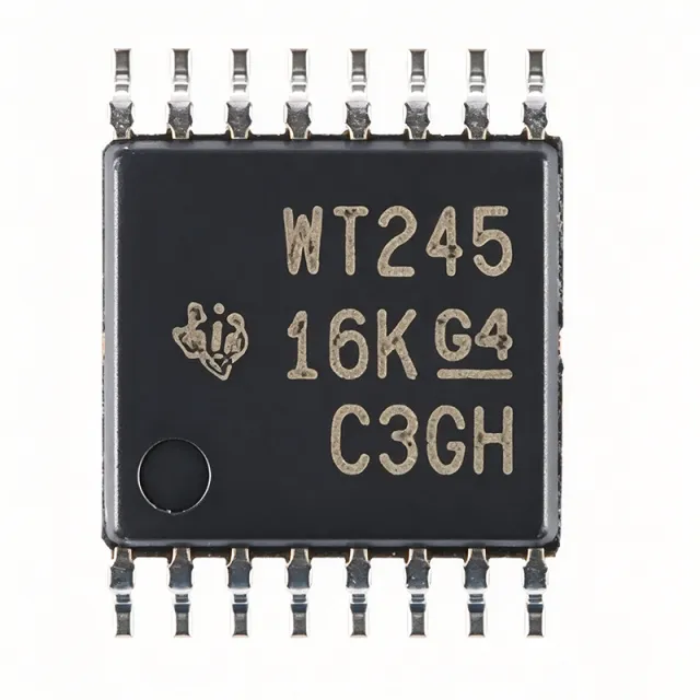
SN74AVC4T245PWR - 4-Bit Dual-Supply Level Shifter | TI
料号: SN74AVC4T245PWR ✓ 量产中| 数量 | 单价 | 小计 |
|---|---|---|
| 1 | $0.72 | $0.72 |
| 10 | $0.63 | $6.30 |
| 100 | $0.51 | $51.00 |
| 500 | $0.44 | $220.00 |
| 1,000 | $0.38 | $380.00 |
SN74AVC4T245PWR 概述
A bus transceiver is a digital integrated circuit that transfers data bidirectionally between two buses, using direction-control and output-enable inputs plus 3-state outputs so multiple devices can share a common bus. The SN74AVC4T245 belongs to the voltage translator (level shifter) family within the broader logic IC and interface IC hierarchy, and it is essential in mixed-voltage systems where MCUs, FPGAs, sensors, and memory operate at different logic levels.
Key features include configurable voltage translation on both ports, control inputs (1DIR, 2DIR, 1OE, 2OE) referenced to VCCA for simplified control logic, and Ioff partial-power-down circuitry that disables outputs and prevents damaging backflow current when either rail is at GND. A VCC isolation feature places all I/O in high-impedance if either supply is absent.
Technically, the device supports asynchronous communication between two data buses at data rates up to 380 Mbps with a typical propagation delay around 2.5 ns, suiting high-speed SPI, parallel bus, and GPIO interfaces. The TSSOP-16 package has a 4.4mm body width and 0.65mm pin pitch for space-constrained PCBs.
Typical applications include level shifting for SPI, UART, I2C-adjacent GPIO expansion, and FPGA or ASIC interconnects in industrial control, portable battery-powered electronics, and automotive modules where multiple voltage domains coexist.
Design tip: keep the DIR and OE pins driven from VCCA-domain logic and place 0.1uF decoupling capacitors close to both VCCA and VCCB pins; avoid bus contention by sequencing direction changes with a brief high-impedance interval.
This page synthesizes distributor pricing, drop-in alternatives, and practical design notes not found in the manufacturer datasheet.
直接替换替代料: SN74AVC4T245PWR ——相同封装,引脚兼容。需要 PCB 改动的不同封装料号已排除。
本系列中的变体
可与以下型号直接替换的同系列型号: SN74AVC4T245PWR (相同外形与封装尺寸) ——差异在于 Package.
快速对比工具——选择替代料号进行并排对比:
SN74AVC4T245QPWRQ1
✅ 直接替换📋 参考替代料(不在目录中)
SN74AVCH4T245PWR
✅ 直接替换📋 参考替代料(不在目录中)
SN74AXC4T245PWR
✅ 直接替换📋 参考替代料(不在目录中)
SN74LVC4T245PWR
✅ 直接替换 ⚠️ 规格未核验📋 参考替代料(不在目录中)
SN74AVC4T245PWR 规格参数
| 功能 | 4-bit dual-supply bus transceiver with configurable voltage translation |
| VCCA Supply Range | 0.8 V to 3.6 V |
| VCCB Supply Range | 0.8 V to 3.6 V |
| Translation Type | Bidirectional, configurable (down/up translation both ports) |
| Bits per Element | 2 elements, 2 bits per element (4-bit total) |
| 输出类型 | 3-State |
| Max Data Rate | 380 Mbps |
| Typical Propagation Delay | 2.5 ns |
| Control Input Reference | VCCA (1DIR, 2DIR, 1OE, 2OE) |
| Ioff Partial-Power-Down | Yes |
| VCC Isolation Feature | Yes (all I/O high impedance if either rail at GND) |
| 封装 | 16-TSSOP (PW), 4.4 mm body width, 0.65 mm pin pitch |
| 工作温度 | -40C to +85C |
| 安装类型 | Surface Mount |
| Marking Code | WT245 |
| AEC-Q100 Qualification | Not applicable (choose SN74AVC4T245QPWRQ1 for AEC-Q100 automotive grade) |
SN74AVC4T245PWR 引脚配置
| 引脚 1 | 1DIR — Direction control for port 1 (VCCA-referenced) |
| 引脚 2 | 1OE — Output enable for port 1 (VCCA-referenced) |
| 引脚 3 | VCCA — A-port supply, 0.8V to 3.6V |
| 引脚 4 | A1 — A-port data I/O, bit 1 |
| 引脚 5 | A2 — A-port data I/O, bit 2 |
| 引脚 6 | GND — Ground |
| 引脚 7 | A3 — A-port data I/O, bit 3 |
| 引脚 8 | A4 — A-port data I/O, bit 4 |
| 引脚 9 | 2DIR — Direction control for port 2 (VCCA-referenced) |
| 引脚 10 | 2OE — Output enable for port 2 (VCCA-referenced) |
| 引脚 11 | B4 — B-port data I/O, bit 4 |
| 引脚 12 | B3 — B-port data I/O, bit 3 |
| 引脚 13 | VCCB — B-port supply, 0.8V to 3.6V |
| 引脚 14 | B2 — B-port data I/O, bit 2 |
| 引脚 15 | B1 — B-port data I/O, bit 1 |
| 引脚 16 | GND — Ground |
典型应用
SN74AVC4T245PWR 适用于 6 应用s: SPI Bus Level Shifting, FPGA and ASIC Bank Interconnect, Industrial Control Systems, Portable Battery-Powered Electronics, Automotive Modules (Q1 Variant), UART and GPIO Expansion.
SPI Bus Level Shifting
The SN74AVC4T245PWR is an excellent SPI level shifter because its 380 Mbps data rate and 2.5 ns typical propagation delay comfortably support SPI clocks up to tens of MHz with minimal timing skew. One channel pair handles MOSI/SCLK from controller to peripheral while the other pair returns MISO, with DIR pins set per direction and 1OE/2OE gating each element independently. Placed between a 1.8V MCU and a 3.3V sensor bank, the device adds negligible delay to SPI timing budgets. Because control inputs are referenced to VCCA, the 1.8V controller drives direction and enable directly without extra translation. Add 0.1uF decoupling on both rails and keep traces short to preserve edge integrity at high SCLK rates.
推荐
FPGA and ASIC Bank Interconnect
Modern FPGAs and ASICs frequently mix 1.8V I/O banks with 3.3V legacy peripherals; the SN74AVC4T245PWR bridges these domains bidirectionally with its 0.8V to 3.6V dual-rail range. Its 2.5 ns propagation delay keeps setup-and-hold margins intact for parallel address/data buses, and 3-state outputs allow the transceiver to release the bus during high-impedance phases for shared-bus topologies. The VCC isolation feature protects the FPGA during power sequencing by forcing all I/O high-impedance if either rail is absent, avoiding latch-up stress on bank pins. With four bits per package, two devices serve an 8-bit parallel interface, and the 16-TSSOP footprint conserves board area near dense FPGA escape routing.
推荐
Industrial Control Systems
Industrial controllers routinely mix 3.3V microcontrollers with 5V-tolerant-tolerated or 2.5V PLC-adjacent logic; the SN74AVC4T245PWR provides robust translation in its -40C to +85C industrial temperature range. The Ioff partial-power-down circuitry prevents damaging backflow current when subsystems power down independently, a common condition in modular industrial cabinets where boards are hot-plugged or selectively de-energized. Direction control referenced to VCCA simplifies interfacing with the 3.3V main MCU. The 380 Mbps capability also covers fast incremental-encoder and parallel communication interfaces. Designers should sequence DIR changes through a brief high-impedance interval via the OE pins to prevent bus contention when reversing a shared industrial data bus.
推荐
Portable Battery-Powered Electronics
Battery-powered products often combine a low-voltage (1.2V or 1.8V) application processor with 3.3V peripheral ICs, and the SN74AVC4T245PWR's 0.8V minimum rail support accommodates deep sub-1V-class core-adjacent I/O as batteries discharge. The Ioff circuitry is particularly valuable in portable designs: when a subsystem is switched off for power saving, the transceiver outputs go high-impedance and block backflow current that would otherwise drain the battery or damage powered-down ICs. The small 16-TSSOP package with 0.65mm pitch suits dense handheld PCBs. At a typical $0.38-$0.72 unit price (as of 2026-09-03), the BOM impact is minimal for consumer electronics platforms.
推荐
Automotive Modules (Q1 Variant)
Automotive ECUs and body-control modules require AEC-Q100 qualification, so designers should specify the SN74AVC4T245QPWRQ1, which is the identical die function and TSSOP-16 pinout qualified for automotive use. Translation tasks mirror the standard part: bridging 1.8V/3.3V domains between microcontrollers, CAN/LIN transceiver digital sides, and sensor arrays. The VCC isolation and Ioff features address automotive power-moding, where individual rails collapse during crank or partial-sleep states without damaging I/O. Because the Q1 part is pin-to-pin identical, dual-sourcing the standard SN74AVC4T245PWR for non-automotive SKUs shares one PCB footprint across product families, reducing qualification and inventory overhead for tier-one suppliers.
推荐
UART and GPIO Expansion
UART links, status lines, and general-purpose I/O between mixed-voltage blocks are classic low-speed uses for the SN74AVC4T245PWR, where its 380 Mbps capability provides large timing headroom well above typical 115200-baud to multi-Mbps UART rates. Each 2-bit element can be independently enabled with 1OE/2OE and steered with 1DIR/2DIR, letting one package serve a TX/RX pair plus two status lines with separate control. The 3-state outputs allow safe sharing of connector-mediated I/O, and the 2.5 ns delay is negligible for asynchronous signaling. For designs where direction changes dynamically, drive DIR through the VCCA-domain logic and observe the datasheet-enable timing to avoid transient contention during turnarounds.
推荐
推荐产品汇总
工程参考数据: SN74AVC4T245PWR ——对比、设计指导和合规信息。
选型指南
与替代料对比
| 参数 | 本产品 | SN74AVC4T245QPWRQ1 | SN74AVCH4T245PWR | SN74AXC4T245PWR | SN74LVC4T245PWR |
|---|---|---|---|---|---|
| Package | 16-TSSOP (PW) | 16-TSSOP (PW) - same | 16-TSSOP (PW) - same | 16-TSSOP (PW) - same | 16-TSSOP (PW) - same |
| Brand | Texas Instruments | Texas Instruments | Texas Instruments | Texas Instruments | Texas Instruments |
| Ioff / VCC Isolation | Yes / Yes | Yes / Yes | Yes / Yes | Yes / Yes | Yes / Yes |
关键差异点
- Highest speed class in the TI 4-bit translator family (对比 SN74LVC4T245PWR)
- Wide 0.8V low-rail support (对比 SN74LVC4T245PWR)
- Cost-qualified drop-in path to automotive (对比 SN74AVC4T245QPWRQ1)
设计说明
Place a 0.1uF ceramic decoupling capacitor within 2-3 mm of both the VCCA (pin 3) and VCCB (pin 13) pins, each returning to its own ground via pin 6/16. Because AVC-class outputs drive very fast edges, supply bounce on an undecoupled rail translates directly into overshoot and ringing on the I/O lines. Estimated: at 380 Mbps with a 15 pF load, per-bit dynamic current can approach tens of milliamps during transitions, so local charge storage is mandatory even at modest duty cycles.
Never change a DIR pin while OE is active on a shared bus - the driver will fight the opposing bus master for a logic state, causing large transient currents and possible long-term degradation. Sequence direction turnarounds by first asserting OE (outputs high-impedance), then switching DIR, then releasing OE after a one-clock settling interval. Also remember control pins are VCCA-referenced: driving 1OE/2OE/DIR from the VCCB domain can violate VIH/VIL thresholds when VCCA is low (e.g., 1.2V).
Keep A-side and B-side routing grouped by port to isolate the two voltage domains, and keep transceiver traces under 10 cm where possible to limit reflection at AVC-class edge rates. TSSOP-16 lead pitch of 0.65 mm is solderable with standard reflow; use the datasheet land-pattern dimensions and add thermal relief-free solid ground connections on pins 6 and 16. Avoid routing fast A/B signals parallel to the DIR/OE control lines for long distances to minimize crosstalk-induced false direction switching.
合规信息
Standard commercial grade (not AEC-Q100); the SN74AVC4T245QPWRQ1 variant is the automotive-qualified option. Verify RoHS/REACH status on the TI product page for the specific orderable suffix.







