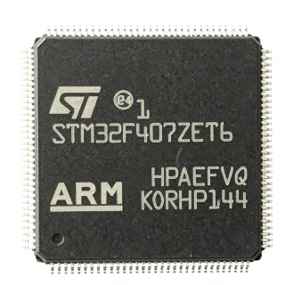
STM32F415ZGT6 - 168MHz ARM Cortex-M4F MCU, 1MB Flash | STMicroelectronics
料号: STM32F415ZGT6 ✓ 量产中| 数量 | 单价 | 小计 |
|---|---|---|
| 1 | $12.5 | $12.50 |
| 10 | $11.25 | $112.50 |
| 100 | $10 | $1,000.00 |
| 500 | $9 | $4,500.00 |
| 1,000 | $8.5 | $8,500.00 |
STM32F415ZGT6 概述
What is an ARM Cortex-M4F microcontroller? It is a 32-bit processor core designed for embedded systems that require a balance of performance, power efficiency, and advanced digital signal processing (DSP) capabilities. The 'F' suffix indicates the presence of a hardware floating-point unit, which accelerates mathematical operations for applications like motor control, audio processing, and sensor fusion. In the system hierarchy, a microcontroller (MCU) integrates the processor core, memory, and peripherals on a single chip, serving as the 'brain' of embedded systems. The STM32F4 series sits in the high-performance tier of ST's STM32 portfolio, positioned above the mainstream F1/F3 series and below the higher-end F7/H7 series.
Key features of the STM32F415ZGT6 include a 168 MHz CPU with 210 DMIPS performance, 1 MB of Flash memory, 192 KB of SRAM, and a comprehensive set of peripherals: three 12-bit ADCs (up to 24 channels), two 12-bit DACs, advanced timers, and multiple communication interfaces (USART, SPI, I2C, USB OTG FS/HS, CAN, SDIO, and Ethernet MAC). The device also features a true random number generator (RNG), a cryptographic acceleration cell (AES, DES, 3DES), and a camera interface (DCMI). These features make it ideal for applications requiring high computational throughput and rich connectivity.
From a technical architecture perspective, the STM32F415ZGT6 is built on a 90nm process technology, offering a good balance of performance and power consumption. The Cortex-M4F core includes a single-precision FPU and DSP instructions, enabling efficient execution of complex algorithms. The memory architecture uses a Harvard bus structure with separate instruction and data buses, allowing simultaneous access to Flash and SRAM. The device supports a wide supply voltage range of 1.8V to 3.6V, with a comprehensive clock management system including a PLL, multiple internal/external oscillators, and a real-time clock (RTC).
Typical applications include industrial motor control, medical devices, consumer electronics, IoT gateways, and audio processing. The combination of high-speed ADC, advanced timers, and Ethernet MAC makes it particularly well-suited for real-time control and networked systems. For example, in a motor control application, the advanced PWM timers and high-resolution ADC enable precise current and speed regulation.
When designing with this device, pay attention to power supply decoupling: place a 100nF capacitor close to each VDD pin and a 4.7uF bulk capacitor on the main supply. Also, ensure proper configuration of the boot pins (BOOT0 and BOOT1) to select the desired boot source. The device supports in-circuit programming and debugging via SWD and JTAG interfaces, facilitating development.
直接替换替代料: STM32F415ZGT6 ——相同封装,引脚兼容。需要 PCB 改动的不同封装料号已排除。
本系列中的变体
可与以下型号直接替换的同系列型号: STM32F415ZGT6 (相同外形与封装尺寸) ——差异在于 ADC, Communication Interfaces, Package, Timers, SRAM.
快速对比工具——选择替代料号进行并排对比:
STM32F407ZGT6
✅ 直接替换✓ 有现货
$5.25 / 个
查看数据手册 →STM32F417ZGT6
✅ 直接替换✓ 有现货
$8.1 / 个
查看数据手册 →STM32F415ZGT7
✅ 直接替换 ⚠️ 规格未核验📋 参考替代料(不在目录中)
STM32F405ZGT6
✅ 直接替换 ⚠️ 规格未核验✓ 有现货
$8.1 / 个
查看数据手册 →STM32F415ZGT6 最大额定值与电气特性
| Core | ARM Cortex-M4F with FPU |
| 最大时钟频率 | 168 MHz |
| Flash Memory | 1 MB |
| SRAM | 192 KB |
| 电源电压 | 1.8V to 3.6V |
| 封装 | LQFP144 (20x20 mm) |
| 引脚数 | 144 |
| GPIO Pins | 114 |
| ADC | 3x 12-bit, up to 24 channels |
| DAC | 2x 12-bit |
| Timers | Advanced-control, general-purpose, basic, and low-power timers |
| Communication Interfaces | USART, SPI, I2C, USB OTG FS/HS, CAN, SDIO, Ethernet MAC |
| 工作温度 | -40C to +85C |
| RoHS 状态 | Compliant |
| DSP Instructions | Yes |
| Floating-Point Unit | Single-precision |
STM32F415ZGT6 引脚配置
| 引脚 1 | PE2 — GPIO / alternate functions |
| 引脚 2 | PE3 — GPIO / alternate functions |
| 引脚 3 | PE4 — GPIO / alternate functions |
| 引脚 4 | PE5 — GPIO / alternate functions |
| 引脚 5 | PE6 — GPIO / alternate functions |
| 引脚 6 | VBAT — Backup battery supply |
| 引脚 7 | PC13 — GPIO / RTC tamper |
| 引脚 8 | PC14 — GPIO / OSC32_IN |
| 引脚 9 | PC15 — GPIO / OSC32_OUT |
| 引脚 10 | PF0 — GPIO / OSC_IN |
| 引脚 11 | PF1 — GPIO / OSC_OUT |
| 引脚 12 | PF2 — GPIO |
| 引脚 13 | PF3 — GPIO |
| 引脚 14 | PF4 — GPIO |
| 引脚 15 | PF5 — GPIO |
| 引脚 16 | PF6 — GPIO |
| 引脚 17 | PF7 — GPIO |
| 引脚 18 | PF8 — GPIO |
| 引脚 19 | PF9 — GPIO |
| 引脚 20 | PF10 — GPIO |
| 引脚 21 | VSS — Ground |
| 引脚 22 | VDD — Power supply |
| 引脚 23 | PF11 — GPIO |
| 引脚 24 | PF12 — GPIO |
| 引脚 25 | PF13 — GPIO |
| 引脚 26 | PF14 — GPIO |
| 引脚 27 | PF15 — GPIO |
| 引脚 28 | PG0 — GPIO |
| 引脚 29 | PG1 — GPIO |
| 引脚 30 | PG2 — GPIO |
| 引脚 31 | PG3 — GPIO |
| 引脚 32 | PG4 — GPIO |
| 引脚 33 | PG5 — GPIO |
| 引脚 34 | PG6 — GPIO |
| 引脚 35 | PG7 — GPIO |
| 引脚 36 | PG8 — GPIO |
| 引脚 37 | PG9 — GPIO |
| 引脚 38 | PG10 — GPIO |
| 引脚 39 | PG11 — GPIO |
| 引脚 40 | PG12 — GPIO |
| 引脚 41 | PG13 — GPIO |
| 引脚 42 | PG14 — GPIO |
| 引脚 43 | PG15 — GPIO |
| 引脚 44 | VSS — Ground |
| 引脚 45 | VDD — Power supply |
| 引脚 46 | PD0 — GPIO / crystal oscillator |
| 引脚 47 | PD1 — GPIO / crystal oscillator |
| 引脚 48 | PD2 — GPIO |
| 引脚 49 | PD3 — GPIO |
| 引脚 50 | PD4 — GPIO |
| 引脚 51 | PD5 — GPIO |
| 引脚 52 | PD6 — GPIO |
| 引脚 53 | PD7 — GPIO |
| 引脚 54 | PD8 — GPIO |
| 引脚 55 | PD9 — GPIO |
| 引脚 56 | PD10 — GPIO |
| 引脚 57 | PD11 — GPIO |
| 引脚 58 | PD12 — GPIO |
| 引脚 59 | PD13 — GPIO |
| 引脚 60 | PD14 — GPIO |
| 引脚 61 | PD15 — GPIO |
| 引脚 62 | PC0 — GPIO / ADC input |
| 引脚 63 | PC1 — GPIO / ADC input |
| 引脚 64 | PC2 — GPIO / ADC input |
| 引脚 65 | PC3 — GPIO / ADC input |
| 引脚 66 | VSSA — Analog ground |
| 引脚 67 | VDDA — Analog power supply |
| 引脚 68 | PC4 — GPIO / ADC input |
| 引脚 69 | PC5 — GPIO / ADC input |
| 引脚 70 | PB0 — GPIO / ADC input |
| 引脚 71 | PB1 — GPIO / ADC input |
| 引脚 72 | PB2 — GPIO |
| 引脚 73 | PB3 — GPIO / JTDO |
| 引脚 74 | PB4 — GPIO / NJTRST |
| 引脚 75 | PB5 — GPIO |
| 引脚 76 | PB6 — GPIO / I2C1_SCL |
| 引脚 77 | PB7 — GPIO / I2C1_SDA |
| 引脚 78 | BOOT0 — Boot mode selection |
| 引脚 79 | PB8 — GPIO / I2C1_SCL |
| 引脚 80 | PB9 — GPIO / I2C1_SDA |
| 引脚 81 | VSS — Ground |
| 引脚 82 | VDD — Power supply |
| 引脚 83 | PE7 — GPIO |
| 引脚 84 | PE8 — GPIO |
| 引脚 85 | PE9 — GPIO |
| 引脚 86 | PE10 — GPIO |
| 引脚 87 | PE11 — GPIO |
| 引脚 88 | PE12 — GPIO |
| 引脚 89 | PE13 — GPIO |
| 引脚 90 | PE14 — GPIO |
| 引脚 91 | PE15 — GPIO |
| 引脚 92 | PB10 — GPIO / I2C2_SCL |
| 引脚 93 | PB11 — GPIO / I2C2_SDA |
| 引脚 94 | PB12 — GPIO / SPI2_NSS |
| 引脚 95 | PB13 — GPIO / SPI2_SCK |
| 引脚 96 | PB14 — GPIO / SPI2_MISO |
| 引脚 97 | PB15 — GPIO / SPI2_MOSI |
| 引脚 98 | PD8 — GPIO / USART3_TX |
| 引脚 99 | PD9 — GPIO / USART3_RX |
| 引脚 100 | PD10 — GPIO / USART3_CK |
| 引脚 101 | PD11 — GPIO / USART3_CTS |
| 引脚 102 | PD12 — GPIO / USART3_RTS |
| 引脚 103 | PD13 — GPIO |
| 引脚 104 | PD14 — GPIO |
| 引脚 105 | PD15 — GPIO |
| 引脚 106 | PC6 — GPIO / I2S2_MCK |
| 引脚 107 | PC7 — GPIO / I2S2_MCK |
| 引脚 108 | PC8 — GPIO / SDIO_D0 |
| 引脚 109 | PC9 — GPIO / SDIO_D1 |
| 引脚 110 | PA0 — GPIO / ADC input / WKUP |
| 引脚 111 | PA1 — GPIO / ADC input |
| 引脚 112 | PA2 — GPIO / USART2_TX |
| 引脚 113 | PA3 — GPIO / USART2_RX |
| 引脚 114 | VSS — Ground |
| 引脚 115 | VDD — Power supply |
| 引脚 116 | PA4 — GPIO / SPI1_NSS |
| 引脚 117 | PA5 — GPIO / SPI1_SCK |
| 引脚 118 | PA6 — GPIO / SPI1_MISO |
| 引脚 119 | PA7 — GPIO / SPI1_MOSI |
| 引脚 120 | PA8 — GPIO / USB_OTG_FS_SOF |
| 引脚 121 | PA9 — GPIO / USB_OTG_FS_VBUS |
| 引脚 122 | PA10 — GPIO / USB_OTG_FS_ID |
| 引脚 123 | PA11 — GPIO / USB_OTG_FS_DM |
| 引脚 124 | PA12 — GPIO / USB_OTG_FS_DP |
| 引脚 125 | PA13 — GPIO / SWDIO |
| 引脚 126 | PA14 — GPIO / SWCLK |
| 引脚 127 | PA15 — GPIO / JTDI |
| 引脚 128 | PC10 — GPIO / SDIO_D2 |
| 引脚 129 | PC11 — GPIO / SDIO_D3 |
| 引脚 130 | PC12 — GPIO / SDIO_CK |
| 引脚 131 | PD0 — GPIO / crystal oscillator |
| 引脚 132 | PD1 — GPIO / crystal oscillator |
| 引脚 133 | PD2 — GPIO |
| 引脚 134 | PD3 — GPIO |
| 引脚 135 | PD4 — GPIO |
| 引脚 136 | PD5 — GPIO |
| 引脚 137 | PD6 — GPIO |
| 引脚 138 | PD7 — GPIO |
| 引脚 139 | VSS — Ground |
| 引脚 140 | VDD — Power supply |
| 引脚 141 | PB0 — GPIO / ADC input |
| 引脚 142 | PB1 — GPIO / ADC input |
| 引脚 143 | PB2 — GPIO |
| 引脚 144 | PB3 — GPIO / JTDO |
典型应用
STM32F415ZGT6 适用于 6 应用s: Industrial Motor Control, IoT Gateway, Medical Device, Audio Processing, Smart Home Controller, Test and Measurement.
Industrial Motor Control
The STM32F415ZGT6 is ideal for industrial motor control due to its advanced timers (TIM1/TIM8) that generate complementary PWM with dead-time insertion, and its high-speed 12-bit ADCs that sample phase currents. The FPU accelerates field-oriented control (FOC) algorithms, enabling efficient and precise motor drives. In a typical application, the MCU reads current sensors via the ADC, executes the FOC algorithm in the FPU, and outputs PWM signals to the gate driver. The Ethernet MAC allows remote monitoring and diagnostics. Compared to lower-end MCUs, the 168 MHz clock and DSP instructions reduce control loop latency, improving dynamic response. Designers should ensure proper isolation between power and control stages and use the ADC's injected channels for synchronized sampling.
推荐
IoT Gateway
The STM32F415ZGT6 serves as a powerful IoT gateway processor, connecting sensors and devices to the cloud. Its Ethernet MAC and USB OTG interfaces enable wired and wireless connectivity, while multiple UARTs/SPIs/I2Cs interface with various sensors and communication modules (e.g., Wi-Fi, LoRa). The cryptographic acceleration and RNG enhance security for TLS/DTLS protocols. In a typical gateway, the MCU aggregates data from sensors, processes it locally, and transmits it to the cloud via Ethernet or a cellular module. The 1 MB Flash allows storing firmware and buffering data. The FPU accelerates data processing, such as sensor fusion algorithms. Designers should consider power consumption and use low-power modes when idle. The device's industrial temperature range ensures reliable operation in outdoor environments.
推荐
Medical Device
The STM32F415ZGT6 is suitable for medical devices such as patient monitors, infusion pumps, and diagnostic equipment. Its high-performance core and FPU enable real-time signal processing for ECG, EEG, and other biosignals. The multiple ADCs and DACs interface with analog front-ends, while the USB OTG supports connectivity to PCs or mobile devices. The cryptographic acceleration ensures secure data transmission, complying with health data privacy regulations. In a typical patient monitor, the MCU samples ECG signals via the ADC, processes them with digital filters, and displays the waveform on an LCD. The device's low power consumption and wide supply voltage range support battery operation. Designers must follow medical safety standards (e.g., IEC 60601) and ensure proper isolation and EMC protection.
推荐
Audio Processing
The STM32F415ZGT6 is well-suited for audio processing applications such as audio effects processors, voice recognition, and active noise cancellation. The Cortex-M4F with FPU and DSP instructions efficiently executes audio algorithms like FIR/IIR filters, FFT, and codecs. The I2S interface connects to audio codecs, and the DAC can output analog audio directly. In a typical audio effects processor, the MCU receives digital audio via I2S, applies effects (e.g., reverb, equalization) in real-time, and outputs the processed audio. The 168 MHz clock ensures low latency. The device's large SRAM (192 KB) buffers audio samples. Designers should pay attention to clock jitter and use a dedicated audio PLL for high-quality audio. The low noise ADC and DAC contribute to high signal-to-noise ratio.
推荐
Smart Home Controller
The STM32F415ZGT6 acts as a central controller in smart home systems, managing lighting, HVAC, security, and appliances. Its rich connectivity (Ethernet, USB, UART, SPI, I2C) allows integration with various smart home protocols (e.g., Zigbee, Z-Wave, Wi-Fi). The device's low power modes enable energy-efficient operation. In a typical smart home hub, the MCU communicates with sensors and actuators, processes user commands, and provides a web interface via Ethernet. The cryptographic acceleration secures communication with cloud services. The 1 MB Flash stores the hub's firmware and configuration. Designers should implement over-the-air (OTA) updates using the dual-bank Flash feature. The device's industrial temperature range ensures reliable operation in home environments.
推荐
Test and Measurement
The STM32F415ZGT6 is used in test and measurement equipment such as oscilloscopes, data loggers, and signal generators. Its high-speed ADCs (up to 2.4 MSPS) and DACs enable precise signal acquisition and generation. The advanced timers provide accurate time base and triggering. In a typical data logger, the MCU samples multiple analog channels, timestamps the data, and stores it on an SD card via SDIO. The USB OTG allows connection to a PC for data analysis. The FPU accelerates signal processing, such as FFT for spectrum analysis. The device's wide supply voltage range and low power consumption support portable instruments. Designers should use external precision references and careful PCB layout to maintain measurement accuracy.
推荐
推荐产品汇总
工程参考数据: STM32F415ZGT6 ——对比、设计指导和合规信息。
选型指南
与替代料对比
| 参数 | 本产品 | STM32F407ZGT6 | STM32F417ZGT6 | STM32F415ZGT7 | STM32F405ZGT6 | LPC4357FET256 |
|---|---|---|---|---|---|---|
| Package | LQFP144 | LQFP144 | LQFP144 | LQFP144 | LQFP144 | BGA256 |
| Brand | STMicroelectronics | STMicroelectronics | STMicroelectronics | STMicroelectronics | STMicroelectronics | NXP Semiconductors |
| Core | ARM Cortex-M4F | ARM Cortex-M4F | ARM Cortex-M4F | ARM Cortex-M4F | ARM Cortex-M4F | ARM Cortex-M4F + M0 |
| Max Clock Frequency | 168 MHz | 168 MHz | 168 MHz | 168 MHz | 168 MHz | 204 MHz |
| Flash Memory | 1 MB | 1 MB | 1 MB | 1 MB | 1 MB | 1 MB |
| SRAM | 192 KB | 192 KB | 192 KB | 192 KB | 192 KB | 136 KB |
| Cryptographic Acceleration | Yes (AES, DES, 3DES) | No | Yes (AES, DES, 3DES) | Yes (AES, DES, 3DES) | No | No |
| Ethernet MAC | Yes | Yes | Yes | Yes | No | Yes |
关键差异点
- Integrated cryptographic acceleration and RNG (对比 STM32F407ZGT6)
- Higher SRAM than some alternatives (对比 LPC4357FET256)
- Pin-compatible with F4 family (对比 STM32F405ZGT6)
设计说明
Decouple each VDD pin with a 100nF ceramic capacitor placed as close as possible to the pin. Additionally, place a 4.7uF bulk capacitor on the main supply rail. For VDDA, use a dedicated 1uF capacitor and a ferrite bead to isolate analog noise. Ensure VSSA is connected to a clean ground plane.
For the LQFP144 package, use a 4-layer PCB with a solid ground plane. Route high-speed signals (Ethernet, USB) with controlled impedance (e.g., 90 ohms differential for USB). Keep crystal oscillator traces short and away from high-current switching traces. Place the decoupling capacitors on the bottom side directly under the MCU if possible.
Ensure BOOT0 pin is pulled low for normal boot from Flash. If using SWD debugging, note that PA13 (SWDIO) and PA14 (SWCLK) are shared with GPIO; do not use them as GPIO in production without disabling debug. Also, the VBAT pin must be connected to a battery or tied to VDD to preserve RTC functionality.
合规信息
RoHS and REACH compliant per STMicroelectronics product page. Not AEC-Q100 qualified; for automotive use, consider STM32F415ZGT7 (extended temp) or other automotive-grade variants.