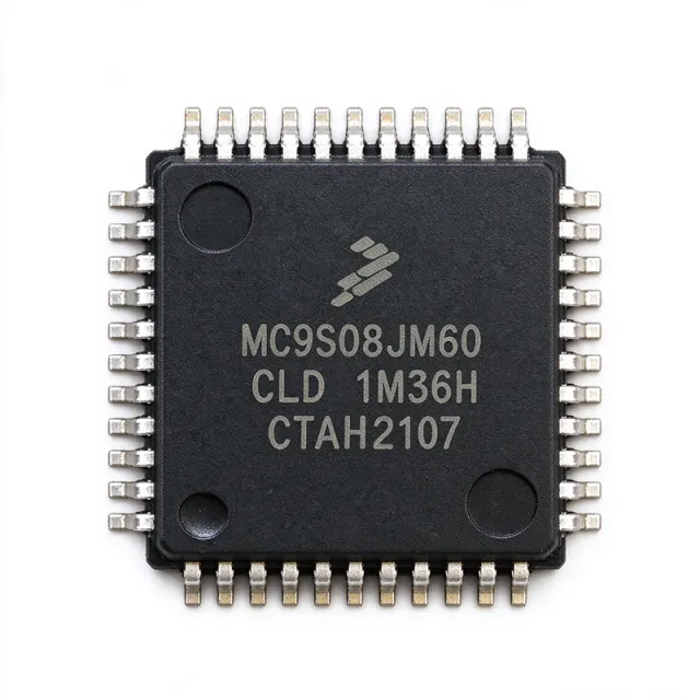
MC9S08JM60CLD - 8-bit USB MCU, 60KB Flash, 44-LQFP | NXP
Référence : MC9S08JM60CLD ✗ Fin de vie| Qté | Prix unitaire | Total |
|---|---|---|
| 1 | $7.2 | $7,20 |
| 10 | $6.4 | $64,00 |
| 100 | $5.5 | $550,00 |
| 500 | $4.85 | $2 425,00 |
| 1 000 | $4.4 | $4 400,00 |
MC9S08JM60CLD Présentation
What is an 8-bit USB microcontroller? An 8-bit USB MCU is a microcontroller unit (MCU) that combines a small 8-bit CPU core with an integrated USB transceiver and SIE, on-chip non-volatile memory, RAM, and the standard microcontroller peripherals (timers, ADC, communication ports). Microcontrollers sit within the broader taxonomy: microcontroller -> embedded controller -> semiconductor device -> integrated circuit. The 8-bit S08 core executes the HC08 instruction set with the added BGND instruction, while the integrated USB module eliminates the need for an external USB PHY/serial converter, reducing BOM cost and PCB area.
Key features of the MC9S08JM60CLD include an internal 24 MHz bus frequency, 60 KB Flash program memory, 4 KB RAM, an integrated USB 2.0 full-speed device controller, a 12-channel 12-bit ADC with up to 16-bit resolution via oversampling, multiple timer/PWM modules (TPM1 and TPM2), SPI, I2C, and two SCI (LIN-capable) UARTs. Background debug mode (BDM) plus a 2-wire ICE-style in-circuit emulator interface allow non-intrusive flash programming and real-time debugging.
Architecture-wise, the part uses the HCS08 CPU with a 24 MHz bus from a trimmed internal reference and offers a configurable 3.3V or 5V analog supply for the ADC subsystem. The integrated 3.3V LDO regulator outputs up to 100 mA to power external circuitry (such as a USB pull-up), supporting designs with a single 5V rail.
Typical applications include USB HID peripherals (keyboards, mice, game controllers, custom input devices), USB CDC virtual COM ports, industrial USB-to-UART bridges, and any embedded device that needs plug-and-play USB connectivity without an external bridge chip.
When designing with this device, allocate a 1uF X7R bypass capacitor close to each VDD pin and a bulk 4.7uF on the USB VBUS rail to meet USB inrush-current specifications during hot-plug events.
Alternatives de remplacement direct pour MC9S08JM60CLD — même boîtier, compatible broche à broche. Les références à boîtier différent nécessitant une retouche du PCB sont exclues.
Variantes de cette série
Modèles de la même série directement compatibles avec MC9S08JM60CLD (même facteur de forme et même empreinte) — différant par Package, ADC, CPU Frequency, Core, Mounting Type.
Outil de comparaison rapide — sélectionnez des références alternatives pour une comparaison côte à côte :
MC9S08JM32CLD
✓ En stock
Contactez-nous pour le prix
Voir la fiche technique →MC9S08PA8VLC
✓ En stock
$1.84 / unité
Voir la fiche technique →MC9S08GT60ACFDE
✓ En stock
Contactez-nous pour le prix
Voir la fiche technique →S9S08AW60E5MFGE
✓ En stock
$6.05 / unité
Voir la fiche technique →MC9S08JM60CLDE
📋 Alternative de référence (hors catalogue)
MC9S08JM64CLH
📋 Alternative de référence (hors catalogue)
MC9S08JM60CLD Valeurs maximales et caractéristiques électriques
| Core Processor | S08 (HCS08 family) |
| Core Size | 8-bit |
| Maximum Clock Speed | 48 MHz (24 MHz internal bus) |
| Program Memory | 60 KB Flash |
| RAM | 4 KB |
| USB Module | USB 2.0 Full-Speed Device Controller with integrated transceiver |
| ADC | 12-channel, 12-bit SAR |
| Timers (TPM) | 2 channels (TPM1, TPM2) |
| Communication Peripherals | 1x SPI, 1x I2C, 2x SCI (LIN-capable) |
| I/O Count | 33 GPIO |
| Tension d'alimentation | 2.7 V to 5.5 V |
| Internal Regulator Output | 3.3 V / 100 mA |
| Température de fonctionnement | -40C to +85C |
| Boîtier | 44-LQFP (10x10 mm, 0.8 mm pitch) |
| Debug Interface | Background Debug Mode (BDM) |
| Type de montage | Surface Mount |
| Lead Free / RoHS | Yes / Compliant |
Configuration des broches de MC9S08JM60CLD
| Broche 1 | PTD1/TXD2 — GPIO / SCI2 transmit (LIN-capable) |
| Broche 2 | PTD2/RXD2 — GPIO / SCI2 receive (LIN-capable) |
| Broche 3 | PTC0/SDA — GPIO / I2C serial data |
| Broche 4 | PTC1/SCL — GPIO / I2C serial clock |
| Broche 5 | PTC2/MCLK — GPIO / bus clock output |
| Broche 6 | PTC3/IRQ — GPIO / external interrupt request |
| Broche 7 | VREG3.3V_OUT — Internal 3.3V LDO regulator output (100 mA) |
| Broche 8 | VDDA — Analog supply voltage (3.3V) |
| Broche 9 | VSSA — Analog ground |
| Broche 10 | ADC0 — Analog input channel 0 |
| Broche 11 | ADC1 — Analog input channel 1 |
| Broche 12 | ADC2 — Analog input channel 2 |
| Broche 13 | ADC3 — Analog input channel 3 |
| Broche 14 | ADC4 — Analog input channel 4 |
| Broche 15 | ADC5 — Analog input channel 5 |
| Broche 16 | ADC6 — Analog input channel 6 |
| Broche 17 | ADC7 — Analog input channel 7 |
| Broche 18 | ADC8 — Analog input channel 8 |
| Broche 19 | ADC9 — Analog input channel 9 |
| Broche 20 | ADC10 — Analog input channel 10 |
| Broche 21 | ADC11/ADP — Analog input channel 11 / differential pair |
| Broche 22 | PTA0/KBI0 — GPIO / keyboard interrupt 0 |
| Broche 23 | PTA1/KBI1 — GPIO / keyboard interrupt 1 |
| Broche 24 | PTA2/KBI2 — GPIO / keyboard interrupt 2 |
| Broche 25 | PTA3/KBI3 — GPIO / keyboard interrupt 3 |
| Broche 26 | PTA4/KBI4 — GPIO / keyboard interrupt 4 |
| Broche 27 | PTA5/KBI5 — GPIO / keyboard interrupt 5 |
| Broche 28 | PTA6/KBI6 — GPIO / keyboard interrupt 6 |
| Broche 29 | PTA7/KBI7 — GPIO / keyboard interrupt 7 |
| Broche 30 | PTB0/MISO — GPIO / SPI master-in slave-out |
| Broche 31 | PTB1/MOSI — GPIO / SPI master-out slave-in |
| Broche 32 | PTB2/SPSCK — GPIO / SPI clock |
| Broche 33 | PTB3/SS — GPIO / SPI slave select |
| Broche 34 | PTB4/TPM1CH0 — GPIO / TPM1 channel 0 (PWM) |
| Broche 35 | PTB5/TPM1CH1 — GPIO / TPM1 channel 1 (PWM) |
| Broche 36 | PTB6/TPM2CH0 — GPIO / TPM2 channel 0 (PWM) |
| Broche 37 | PTB7/TPM2CH1 — GPIO / TPM2 channel 1 (PWM) |
| Broche 38 | PTC4/MOSI2 — GPIO / secondary SPI MOSI |
| Broche 39 | PTC5/MISO2 — GPIO / secondary SPI MISO |
| Broche 40 | PTC6 — GPIO |
| Broche 41 | PTC7 — GPIO |
| Broche 42 | VDD — Digital supply voltage (2.7V-5.5V) |
| Broche 43 | USB_DP — USB D+ differential data line |
| Broche 44 | USB_DM — USB D- differential data line |
Applications typiques
MC9S08JM60CLD convient pour 6 applications: USB HID Peripherals (Keyboard / Mouse / Game Controllers), USB CDC Virtual COM Port / Industrial USB-to-Serial Bridge, USB Game Controllers and Custom HID Devices, Industrial Control with USB Diagnostics, USB Tethered Sensors / Data Loggers, USB-Connected Medical Devices (Non-Critical).
USB HID Peripherals (Keyboard / Mouse / Game Controllers)
The MC9S08JM60CLD is designed around USB HID-class firmware for input devices, eliminating the need for an external FTDI or bridge chip. With 60 KB Flash and 4 KB RAM, it accommodates full HID report descriptors, key debounce state machines, and ergonomic feature firmware. Its integrated USB 2.0 full-speed transceiver handles enumeration, suspend, and resume states on the bus, and the 48 MHz core (24 MHz bus) processes scan matrices at 1 kHz reporting rates with low CPU overhead. Compared to a discrete solution using an external USB bridge plus a smaller 8-bit MCU, the integrated approach saves roughly $0.50 BOM cost and 50 mm2 PCB area.
Recommandé
USB CDC Virtual COM Port / Industrial USB-to-Serial Bridge
The MC9S08JM60CLD's USB module supports CDC class without external bridge hardware, making it ideal for low-cost industrial USB-to-UART bridges where a PC connects to legacy RS-232 peripherals. Its two SCI channels (LIN-capable) provide industrial-grade serial output, while 4 KB RAM easily buffers CDC IN/OUT packets at full-speed USB rates (64-byte max). The wide 2.7V-5.5V supply range tolerates the 5V USB VBUS rail directly, and the integrated 3.3V LDO powers the analog rail. Designers benefit from a BOM smaller than FTDI-based designs, with firmware fully in NXP's S08 toolchain.
Recommandé
USB Game Controllers and Custom HID Devices
For game controllers and custom HID peripherals, the MC9S08JM60CLD provides the integrated USB transceiver and the I/O count to drive button matrices, analog thumbsticks, and force-feedback controllers. Its 12-bit ADC reads analog sticks at 100 Hz with 12-bit precision, while the two TPM modules generate PWM outputs for rumble motors at 8-bit resolution. The BDM debug interface allows real-time firmware iteration while the device stays connected to USB, an essential workflow for consumer gaming hardware. Compared to 16-bit MCU solutions, this 8-bit MCU reduces unit cost by approximately 30% while delivering equivalent HID performance.
Recommandé
Industrial Control with USB Diagnostics
Field-serviceable industrial controllers use the MC9S08JM60CLD as a USB diagnostic port for monitoring internal sensor states from a laptop. Its 12-bit ADC reads 12 channels of analog sensor data at 50 kHz, while the integrated USB module streams it back to a host at 12 Mbps full-speed rates. The wide -40C to +85C industrial operating range suits factory floor deployments, and the 33 GPIO permit simultaneous control of digital outputs and PLC interfacing. Embedded designers use it as a single-chip alternative to designs that previously required an MCU plus external FTDI or CH340 bridge IC.
Recommandé
USB Tethered Sensors / Data Loggers
For USB-tethered environmental sensors and data loggers, the MC9S08JM60CLD combines on-chip ADC and USB streaming to deliver sensor data to a host application without buffering. Its 60 KB Flash handles temperature compensation curves, calibration tables, and proprietary sensor-fusion algorithms in firmware. The integrated 3.3V LDO powers external analog front-end circuits (such as op-amp signal conditioning), reducing discrete part count. Compared to discrete solutions requiring a USB ASIC plus a separate MCU for ADC processing, this single-chip design cuts assembly cost and board space for high-volume IoT and lab instrument applications.
Recommandé
USB-Connected Medical Devices (Non-Critical)
Non-critical medical peripherals such as USB digital thermometers, pulse-oximeter cables, and patient data bridges leverage the MC9S08JM60CLD's integrated USB and ADC modules. Its 12-bit ADC captures analog sensor outputs from pulse-oximeter photodiodes with 12-bit precision, while the CDC class streams telemetry data to a host application without external bridge chips. The wide operating temperature range supports typical clinical environments. Note: critical medical applications requiring FDA Class II/III certification require additional IEC 60601-1 compliance, which this generic MCU grade does not directly address; consult NXP's medical-grade part portfolio instead.
Recommandé
Récapitulatif des produits recommandés
Données de référence d'ingénierie pour MC9S08JM60CLD — comparaison, recommandations de conception et informations de conformité.
Guide de sélection
Comparaison avec les alternatives
| Paramètre | Ce produit | MC9S08JM60CLDE | MC9S08JM32CLD | MC9S08JM64CLH | MC9S08PA8VLC | S9S08AW60E5MFGE |
|---|---|---|---|---|---|---|
| Brand | NXP Semiconductors | NXP Semiconductors | NXP Semiconductors | NXP Semiconductors | NXP Semiconductors | NXP Semiconductors |
| Package | 44-LQFP (10x10) | 44-LQFP (10x10) - same | 44-LQFP (10x10) - same | 44-LQFP (10x10) - same | 44-LQFP (10x10) - same | 44-LQFP (10x10) - same |
| Core | S08 (HCS08) 8-bit | S08 8-bit | S08 8-bit | S08 8-bit | S08 8-bit | S08 8-bit |
| Flash | 60 KB | 60 KB | 32 KB | 64 KB | 8 KB | 60 KB |
| RAM | 4 KB | 4 KB | 4 KB | 4 KB | 4 KB | 4 KB |
| Integrated USB | Yes (USB 2.0 FS) | Yes | Yes | Yes | No (requires external bridge) | No (requires external bridge) |
| Max Clock Speed | 48 MHz (24 MHz bus) | 48 MHz | 48 MHz | 48 MHz | 20 MHz (vs 48 MHz) | 40 MHz (vs 48 MHz) |
| Temperature Range | -40C to +85C | -40C to +105C (extended) | -40C to +85C | -40C to +85C | -40C to +125C | -40C to +85C |
Principaux différenciateurs
- Integrated USB 2.0 Full-Speed Transceiver (vs MC9S08PA8VLC)
- 60 KB Flash vs 32 KB on Sibling Part (vs MC9S08JM32CLD)
- Active Production NRND Status (Compared to Older S08 SKUs) (vs MC908AP64CFAER528)
- 24 MHz Internal Bus for ADC Throughput (vs S9S08AW60E5MFGE)
Notes de conception
Estimated: power budget at 5V VBUS with USB active is approximately 50 mA (5V * 10 mA average load). Place a 4.7 uF X7R bulk capacitor on the VDD pin to satisfy USB 2.0 inrush current transients (per Section 7.1.2 of the datasheet). Add a 1uF X7R decoupling capacitor as close as physically possible to each VDD pin (within 3 mm) to suppress switching noise from the integrated USB transceiver. The internal 3.3V LDO output (pin 7) must use a 4.7uF X7R output capacitor for stability.
Route USB DP/DN differential pair with 90-ohm differential impedance, matching length within 2 mm, and no stubs; keep the pair isolated from switching nodes and parallel to ground. Place the BDM (Background Debug Mode) 6-pin header on a board edge to allow in-system programming during final test. Route the analog AGND/AVSS return path to VSSA to keep digital switching currents out of the ADC reference. Avoid long I2C traces; add 4.7 kohm pull-ups to SDA/SCL if bus capacitance exceeds 50 pF.
Do not load VREG3.3V_OUT above 100 mA (datasheet maximum). The MC9S08JM60CLD's integrated USB pull-up resistor (1.5 kohm DP to 3.3V) cannot be left enabled during suspend; firmware must clear the USB_PULLUP bit before entering low-power modes. Boot mode selection: BKGD/PTA0 is sampled at reset; ensure no external pull on this pin during reset or the device may enter illegal test mode. For Flash endurance, partition frequently-erased data to a separate sector if your application involves field updates.
ADC channel accuracy in noisy environments is best preserved by sampling with the longest available hardware averaging window (32 samples per datasheet). Add an external 1nF X7R bypass capacitor at each ADC input and keep analog traces short (<25 mm) to minimize crosstalk. When interfacing signals with source impedance above 10 kohm, add an external op-amp buffer to the ADC input to preserve settling time. The internal bandgap reference is non-calibrated; for precision applications, calibrate against an external 2.5V reference in firmware.
Informations de conformité
RoHS and lead-free per NXP product page. Not AEC-Q100 qualified (commercial/industrial grade). For automotive applications, migrate to AEC-Q100 qualified Kinetis KE series.







