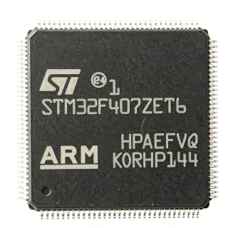
STM32F207ZET6 - 32-bit ARM Cortex-M3 MCU, 512KB Flash | STMicroelectronics
Référence : STM32F207ZET6 ✓ Actif| Qté | Prix unitaire | Total |
|---|---|---|
| 1 | $12.5 | $12,50 |
| 10 | $11.2 | $112,00 |
| 100 | $9.8 | $980,00 |
| 500 | $8.9 | $4 450,00 |
| 1 000 | $8.1 | $8 100,00 |
STM32F207ZET6 Présentation
What is a microcontroller? A microcontroller (MCU) is a compact integrated circuit designed to govern a specific operation in an embedded system. It integrates a processor core, memory (Flash and SRAM), and programmable input/output peripherals on a single chip. Microcontrollers are the brain of countless electronic products, from automotive engine control units to consumer appliances and IoT devices. The STM32F207ZET6 belongs to the STM32F2 series, which is part of the broader STM32 family of 32-bit ARM Cortex-M microcontrollers, positioned between the mainstream F1 series and the high-performance F4/H7 series.
Key features of the STM32F207ZET6 include a 120 MHz ARM Cortex-M3 core with 1.25 DMIPS/MHz, 512 KB Flash, 128 KB SRAM, and a comprehensive set of peripherals: 3x 12-bit ADCs, 2x DACs, 4x USARTs, 2x UARTs, 3x SPI, 2x I2C, 2x CAN, 1x USB 2.0 OTG FS/HS, 1x Ethernet MAC, and a camera interface. It also includes a cryptographic/hash processor for AES, DES, and 3DES encryption, and a true random number generator (TRNG). The device operates from 1.8V to 3.6V supply and supports a temperature range of -40°C to +85°C (industrial grade).
The STM32F207ZET6 is built on ST's advanced 90nm process technology, providing a balance of performance and power efficiency. The ART Accelerator™ (Adaptive Real-Time memory accelerator) enables zero-wait-state execution from Flash, maximizing the effective throughput of the Cortex-M3 core. The device also features a flexible memory controller (FMC) supporting external memory interfaces, including SRAM, PSRAM, NOR, and NAND Flash.
Typical applications include industrial control systems, motor drives, PLCs, medical devices, point-of-sale terminals, networking equipment, and IoT gateways. The rich connectivity (Ethernet, USB, CAN) makes it ideal for applications requiring multiple communication interfaces. The cryptographic hardware accelerates secure communication protocols, enhancing data security in connected devices.
When designing with this MCU, pay attention to power supply decoupling: place 100nF capacitors close to each VDD pin and a 4.7uF bulk capacitor. The VDDA analog supply should be filtered with a ferrite bead and 1uF capacitor to reduce noise for ADC accuracy. Also, configure the boot pins correctly to select the desired boot source (Flash, SRAM, or system memory).
Alternatives de remplacement direct pour STM32F207ZET6 — même boîtier, compatible broche à broche. Les références à boîtier différent nécessitant une retouche du PCB sont exclues.
Variantes de cette série
Modèles de la même série directement compatibles avec STM32F207ZET6 (même facteur de forme et même empreinte) — différant par ADC, DMA, Core, Flash Memory, SRAM.
Outil de comparaison rapide — sélectionnez des références alternatives pour une comparaison côte à côte :
STM32F207ZGT6
✅ Remplacement direct ⚠️ Spécifications non vérifiées✓ En stock
$8.1 / unité
Voir la fiche technique →STM32F407ZET6
✅ Remplacement direct ⚠️ Spécifications non vérifiées✓ En stock
$6.6023 / unité
Voir la fiche technique →STM32F405ZET6
✅ Remplacement direct ⚠️ Spécifications non vérifiées📋 Alternative de référence (hors catalogue)
STM32F207ZET6 Valeurs maximales et caractéristiques électriques
| Core | ARM Cortex-M3 |
| Max Clock Frequency | 120 MHz |
| Flash Memory | 512 KB |
| SRAM | 128 KB |
| Tension d'alimentation | 1.8V to 3.6V |
| Température de fonctionnement | -40°C to +85°C |
| Boîtier | LQFP144 (20x20 mm) |
| Number of I/Os | 114 |
| ADC | 3x 12-bit, up to 24 channels |
| DAC | 2x 12-bit |
| USART/UART | 4x USART, 2x UART |
| SPI | 3x SPI |
| I2C | 2x I2C |
| CAN | 2x CAN 2.0B |
| USB | USB 2.0 OTG FS/HS |
| Ethernet | 10/100 MAC |
| Cryptographic Acceleration | AES, DES, 3DES, TRNG |
| DMA | 16-channel DMA |
| Timers | 12x 16-bit, 2x 32-bit |
| RoHS | Compliant |
Configuration des broches de STM32F207ZET6
| Broche 1 | PE2 — GPIO / TRACECLK |
| Broche 2 | PE3 — GPIO / TRACED0 |
| Broche 3 | PE4 — GPIO / TRACED1 |
| Broche 4 | PE5 — GPIO / TRACED2 |
| Broche 5 | PE6 — GPIO / TRACED3 |
| Broche 6 | VBAT — Backup battery supply |
| Broche 7 | PC13 — GPIO / RTC / Tamper |
| Broche 8 | PC14 — GPIO / OSC32_IN |
| Broche 9 | PC15 — GPIO / OSC32_OUT |
| Broche 10 | PF0 — GPIO / OSC_IN |
| Broche 11 | PF1 — GPIO / OSC_OUT |
| Broche 12 | PF2 — GPIO |
| Broche 13 | PF3 — GPIO |
| Broche 14 | PF4 — GPIO |
| Broche 15 | PF5 — GPIO |
| Broche 16 | PF6 — GPIO |
| Broche 17 | PF7 — GPIO |
| Broche 18 | PF8 — GPIO |
| Broche 19 | PF9 — GPIO |
| Broche 20 | PF10 — GPIO |
| Broche 21 | VSS — Ground |
| Broche 22 | VDD — Power supply |
| Broche 23 | PF11 — GPIO |
| Broche 24 | PF12 — GPIO |
| Broche 25 | PF13 — GPIO |
| Broche 26 | PF14 — GPIO |
| Broche 27 | PF15 — GPIO |
| Broche 28 | PG0 — GPIO |
| Broche 29 | PG1 — GPIO |
| Broche 30 | PG2 — GPIO |
| Broche 31 | PG3 — GPIO |
| Broche 32 | PG4 — GPIO |
| Broche 33 | PG5 — GPIO |
| Broche 34 | PG6 — GPIO |
| Broche 35 | PG7 — GPIO |
| Broche 36 | PG8 — GPIO |
| Broche 37 | PG9 — GPIO |
| Broche 38 | PG10 — GPIO |
| Broche 39 | PG11 — GPIO |
| Broche 40 | PG12 — GPIO |
| Broche 41 | PG13 — GPIO |
| Broche 42 | PG14 — GPIO |
| Broche 43 | PG15 — GPIO |
| Broche 44 | VSS — Ground |
| Broche 45 | VDD — Power supply |
| Broche 46 | PD0 — GPIO / FSMC_D2 |
| Broche 47 | PD1 — GPIO / FSMC_D3 |
| Broche 48 | PD2 — GPIO / FSMC_D4 |
| Broche 49 | PD3 — GPIO / FSMC_D5 |
| Broche 50 | PD4 — GPIO / FSMC_D6 |
| Broche 51 | PD5 — GPIO / FSMC_D7 |
| Broche 52 | PD6 — GPIO / FSMC_D8 |
| Broche 53 | PD7 — GPIO / FSMC_D9 |
| Broche 54 | PD8 — GPIO / FSMC_D10 |
| Broche 55 | PD9 — GPIO / FSMC_D11 |
| Broche 56 | PD10 — GPIO / FSMC_D12 |
| Broche 57 | PD11 — GPIO / FSMC_D13 |
| Broche 58 | PD12 — GPIO / FSMC_D14 |
| Broche 59 | PD13 — GPIO / FSMC_D15 |
| Broche 60 | PD14 — GPIO / FSMC_D0 |
| Broche 61 | PD15 — GPIO / FSMC_D1 |
| Broche 62 | VSS — Ground |
| Broche 63 | VDD — Power supply |
| Broche 64 | PC0 — GPIO / ADC_IN10 |
| Broche 65 | PC1 — GPIO / ADC_IN11 |
| Broche 66 | PC2 — GPIO / ADC_IN12 |
| Broche 67 | PC3 — GPIO / ADC_IN13 |
| Broche 68 | PC4 — GPIO / ADC_IN14 |
| Broche 69 | PC5 — GPIO / ADC_IN15 |
| Broche 70 | PB0 — GPIO / ADC_IN8 |
| Broche 71 | PB1 — GPIO / ADC_IN9 |
| Broche 72 | PB2 — GPIO / BOOT1 |
| Broche 73 | PB3 — GPIO / JTDO |
| Broche 74 | PB4 — GPIO / NJTRST |
| Broche 75 | PB5 — GPIO |
| Broche 76 | PB6 — GPIO / I2C1_SCL |
| Broche 77 | PB7 — GPIO / I2C1_SDA |
| Broche 78 | PB8 — GPIO / I2C1_SCL |
| Broche 79 | PB9 — GPIO / I2C1_SDA |
| Broche 80 | VSS — Ground |
| Broche 81 | VDD — Power supply |
| Broche 82 | PB10 — GPIO / I2C2_SCL |
| Broche 83 | PB11 — GPIO / I2C2_SDA |
| Broche 84 | PB12 — GPIO / SPI2_NSS |
| Broche 85 | PB13 — GPIO / SPI2_SCK |
| Broche 86 | PB14 — GPIO / SPI2_MISO |
| Broche 87 | PB15 — GPIO / SPI2_MOSI |
| Broche 88 | PD8 — GPIO / USART3_TX |
| Broche 89 | PD9 — GPIO / USART3_RX |
| Broche 90 | PD10 — GPIO / USART3_CK |
| Broche 91 | PD11 — GPIO / USART3_CTS |
| Broche 92 | PD12 — GPIO / USART3_RTS |
| Broche 93 | PD13 — GPIO / USART3_DE |
| Broche 94 | PD14 — GPIO / USART3_IRDA |
| Broche 95 | PD15 — GPIO / USART3_IRDA |
| Broche 96 | VSS — Ground |
| Broche 97 | VDD — Power supply |
| Broche 98 | PE0 — GPIO / TIM4_ETR |
| Broche 99 | PE1 — GPIO / TIM4_CH1 |
| Broche 100 | PE2 — GPIO / TIM4_CH2 |
| Broche 101 | PE3 — GPIO / TIM4_CH3 |
| Broche 102 | PE4 — GPIO / TIM4_CH4 |
| Broche 103 | PE5 — GPIO / TIM9_CH1 |
| Broche 104 | PE6 — GPIO / TIM9_CH2 |
| Broche 105 | PE7 — GPIO / TIM1_ETR |
| Broche 106 | PE8 — GPIO / TIM1_CH1 |
| Broche 107 | PE9 — GPIO / TIM1_CH2 |
| Broche 108 | PE10 — GPIO / TIM1_CH3 |
| Broche 109 | PE11 — GPIO / TIM1_CH4 |
| Broche 110 | PE12 — GPIO / TIM1_CH1N |
| Broche 111 | PE13 — GPIO / TIM1_CH2N |
| Broche 112 | PE14 — GPIO / TIM1_CH3N |
| Broche 113 | PE15 — GPIO / TIM1_CH4N |
| Broche 114 | VSS — Ground |
| Broche 115 | VDD — Power supply |
| Broche 116 | PA0 — GPIO / ADC_IN0 / WKUP |
| Broche 117 | PA1 — GPIO / ADC_IN1 |
| Broche 118 | PA2 — GPIO / ADC_IN2 / USART2_TX |
| Broche 119 | PA3 — GPIO / ADC_IN3 / USART2_RX |
| Broche 120 | PA4 — GPIO / ADC_IN4 / SPI1_NSS |
| Broche 121 | PA5 — GPIO / ADC_IN5 / SPI1_SCK |
| Broche 122 | PA6 — GPIO / ADC_IN6 / SPI1_MISO |
| Broche 123 | PA7 — GPIO / ADC_IN7 / SPI1_MOSI |
| Broche 124 | PA8 — GPIO / TIM1_CH1 |
| Broche 125 | PA9 — GPIO / TIM1_CH2 / USART1_TX |
| Broche 126 | PA10 — GPIO / TIM1_CH3 / USART1_RX |
| Broche 127 | PA11 — GPIO / TIM1_CH4 / USB_DM |
| Broche 128 | PA12 — GPIO / TIM1_ETR / USB_DP |
| Broche 129 | PA13 — GPIO / JTMS-SWDIO |
| Broche 130 | PA14 — GPIO / JTCK-SWCLK |
| Broche 131 | PA15 — GPIO / JTDI |
| Broche 132 | VSS — Ground |
| Broche 133 | VDD — Power supply |
| Broche 134 | PC10 — GPIO / UART4_TX |
| Broche 135 | PC11 — GPIO / UART4_RX |
| Broche 136 | PC12 — GPIO / UART5_TX |
| Broche 137 | PC13 — GPIO / RTC_AF1 |
| Broche 138 | PC14 — GPIO / OSC32_IN |
| Broche 139 | PC15 — GPIO / OSC32_OUT |
| Broche 140 | PH0 — GPIO / OSC_IN |
| Broche 141 | PH1 — GPIO / OSC_OUT |
| Broche 142 | NRST — Reset (active low) |
| Broche 143 | VSS — Ground |
| Broche 144 | VDD — Power supply |
Applications typiques
STM32F207ZET6 convient pour 6 applications: Industrial Control, IoT Gateway, Medical Devices, Networking Equipment, Motor Control, Point-of-Sale (POS) Terminals.
Industrial Control
The STM32F207ZET6 is ideal for industrial control systems such as PLCs, motor drives, and factory automation. Its 120 MHz Cortex-M3 core, rich timer set, and multiple communication interfaces (CAN, UART, SPI) enable precise real-time control. The device's robust operating temperature range (-40°C to +85°C) and 5V-tolerant I/Os simplify interfacing with industrial sensors and actuators. In a typical PLC, the MCU manages digital I/O scanning, analog input acquisition via the 12-bit ADCs, and communication with HMI over Ethernet or RS-485. The cryptographic accelerator can secure firmware updates and communication protocols, enhancing system security. With 512 KB Flash, complex control algorithms and communication stacks can be stored without external memory. The FMC allows expansion with external SRAM or NOR Flash if needed. The 16-channel DMA offloads data transfers, reducing CPU load for high-speed data logging. Overall, the STM32F207ZET6 provides a balanced combination of performance, connectivity, and reliability for demanding industrial environments.
Recommandé
IoT Gateway
The STM32F207ZET6 is well-suited for IoT gateways that aggregate data from multiple sensors and communicate with the cloud. Its Ethernet MAC and USB OTG HS provide wired connectivity, while external modules can add Wi-Fi or cellular. The cryptographic hardware accelerates TLS/DTLS for secure cloud communication. The 128 KB SRAM supports buffering of sensor data, and the 512 KB Flash can hold a full RTOS, protocol stacks (MQTT, CoAP), and application code. The device's low power modes (Sleep, Stop, Standby) enable energy-efficient operation when idle. In a typical gateway, the MCU collects data from sensors via UART, SPI, or I2C, processes it, and forwards it to the cloud over Ethernet. The TRNG ensures secure key generation for authentication. The camera interface can support video streaming in advanced gateways. With its rich connectivity and security features, the STM32F207ZET6 is a cost-effective choice for industrial IoT gateways.
Recommandé
Medical Devices
The STM32F207ZET6 is used in medical devices such as patient monitors, infusion pumps, and diagnostic equipment. Its high performance and rich analog peripherals (3x 12-bit ADCs, 2x DACs) enable precise signal acquisition and control. The device's reliability and long-term availability make it suitable for medical applications. In a patient monitor, the MCU acquires ECG, SpO2, and blood pressure signals via the ADCs, processes them with digital filters, and displays waveforms on an LCD. The Ethernet or USB interface allows data transfer to a central monitoring system. The cryptographic accelerator can secure patient data in compliance with regulations. The 512 KB Flash accommodates complex algorithms and user interfaces. The device's low power consumption is beneficial for portable devices. With its combination of performance, analog integration, and security, the STM32F207ZET6 meets the stringent requirements of medical electronics.
Recommandé
Networking Equipment
The STM32F207ZET6 is suitable for networking equipment such as routers, switches, and network interface cards. Its Ethernet MAC supports 10/100 Mbps, and the device can handle protocol processing for TCP/IP, UDP, and other stacks. The cryptographic accelerator enables IPsec and SSL/TLS acceleration. In a managed switch, the MCU manages the switch fabric, handles SNMP, and provides a web interface. The 128 KB SRAM is sufficient for packet buffering, and the DMA channels efficiently move data between Ethernet and memory. The device's multiple UARTs and SPI interfaces allow connection to PHYs and other peripherals. The STM32F207ZET6's performance and connectivity make it a solid choice for cost-sensitive networking applications.
Recommandé
Motor Control
The STM32F207ZET6 is well-suited for motor control applications, including brushless DC (BLDC), permanent magnet synchronous (PMSM), and stepper motors. Its advanced timer peripherals generate PWM signals with dead-time insertion, and the 12-bit ADCs sample phase currents and rotor position. The 120 MHz Cortex-M3 core executes field-oriented control (FOC) algorithms efficiently. In a typical BLDC motor drive, the MCU reads Hall sensors or encoder feedback, computes the commutation sequence, and generates six-step PWM signals. The ADC channels measure phase currents for closed-loop control. The device's CAN interface allows networking with other drives in a multi-axis system. The cryptographic accelerator can secure firmware updates. With its rich timer and analog features, the STM32F207ZET6 provides a complete motor control solution.
Recommandé
Point-of-Sale (POS) Terminals
The STM32F207ZET6 is used in POS terminals for payment processing, inventory management, and customer interaction. Its USB OTG HS supports high-speed communication with peripherals like barcode scanners and receipt printers. The cryptographic accelerator enables secure payment transactions (EMV, PCI-DSS). The device's rich connectivity (Ethernet, USB, UART) allows integration with various payment networks. In a POS terminal, the MCU manages the touchscreen display, reads card data via a magnetic stripe reader or contactless interface, and communicates with the payment gateway over Ethernet or Wi-Fi. The 512 KB Flash stores the application and transaction logs. The device's security features protect sensitive data. With its performance and security, the STM32F207ZET6 is a reliable choice for POS systems.
Recommandé
Récapitulatif des produits recommandés
Données de référence d'ingénierie pour STM32F207ZET6 — comparaison, recommandations de conception et informations de conformité.
Guide de sélection
Comparaison avec les alternatives
| Paramètre | Ce produit | STM32F207ZGT6 | STM32F407ZET6 | STM32F405ZET6 | LPC1788FBD208 |
|---|---|---|---|---|---|
| Package | LQFP144 | LQFP144 | LQFP144 | LQFP144 | LQFP208 |
| Brand | STMicroelectronics | STMicroelectronics | STMicroelectronics | STMicroelectronics | NXP Semiconductors |
| Core | ARM Cortex-M3 | ARM Cortex-M3 | ARM Cortex-M4 | ARM Cortex-M4 | ARM Cortex-M3 |
| Max Clock Frequency | 120 MHz | 120 MHz | 168 MHz | 168 MHz | 120 MHz |
| Flash Memory | 512 KB | 1 MB | 512 KB | 512 KB | 512 KB |
| SRAM | 128 KB | 128 KB | 192 KB | 192 KB | 96 KB |
| Ethernet MAC | Yes | Yes | Yes | No | Yes |
| USB OTG HS | Yes | Yes | Yes | Yes | Yes |
| Cryptographic Acceleration | Yes | Yes | Yes | Yes | No |
Principaux différenciateurs
- Higher Flash capacity option (vs STM32F207ZET6 vs STM32F207ZGT6)
- Cortex-M4 upgrade path (vs STM32F207ZET6 vs STM32F407ZET6)
- Integrated Ethernet and crypto (vs STM32F207ZET6 vs LPC1788FBD208)
Notes de conception
Decouple each VDD pin with a 100nF ceramic capacitor placed as close as possible to the pin. Add a 4.7uF bulk capacitor on the main supply. For VDDA, use a ferrite bead and a 1uF capacitor to filter analog noise. Ensure VDD and VDDA are connected through a low-impedance path.
For the LQFP144 package, use a 4-layer PCB with a solid ground plane. Route high-speed signals (Ethernet, USB) with controlled impedance (e.g., 90 ohms differential for USB). Keep crystal oscillator traces short and away from noisy signals. Place the decoupling capacitors on the bottom side directly under the MCU if possible.
Ensure the BOOT0 pin is correctly configured to boot from Flash (tied low). Do not leave NRST floating; connect a 100nF capacitor to ground. For Ethernet, use a magnetics module with proper termination. When using the cryptographic accelerator, ensure the clock is enabled and the TRNG is seeded correctly.
Informations de conformité
RoHS compliant per ST product page. Not AEC-Q100 qualified; for automotive, consider STM32F207ZET6Q or other automotive-grade variants.