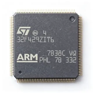
STM32F429ZIT6TR - 2MB Flash 180MHz Cortex-M4 MCU | STMicroelectronics (Tape & Reel)
MPN: STM32F429ZIT6TR ✓ AktifSTM32F429ZIT6TR Ringkasan
What is a microcontroller? A microcontroller (MCU) is a compact integrated circuit that governs a specific operation in an embedded system, combining a processor core, flash memory, SRAM, and programmable peripherals on a single chip. The STM32F429ZIT6TR sits within the STM32F4 series, part of the broader STM32 family of 32-bit ARM Cortex-M microcontrollers, which in turn belongs to the general hierarchy of embedded processors and system-on-chip devices used across industrial, consumer, and IoT applications.
Key features include the ARM Cortex-M4 core with single-precision FPU and DSP instructions, ART Accelerator enabling 0-wait-state execution from flash, and 225 DMIPS (1.25 DMIPS/MHz at 180 MHz). Memory resources total 2 MB of flash and 256 KB of system SRAM plus 4 KB of backup SRAM. Peripheral integration is extensive: three 12-bit ADCs, two DACs, 12 general-purpose 16-bit timers plus two 32-bit timers, multiple USART/SPI/I2C interfaces, USB OTG full-speed and high-speed, 10/100 Ethernet MAC, and a TFT-LCD parallel interface (8080/6800) that supports up to XGA resolution. Supply voltage range is 1.8V to 3.6V (3.3V typical).
Architecturally, the adaptive real-time (ART) accelerator pairs with the dual-bank flash organization to support read-while-write operation, which is critical for in-field or over-the-air firmware updates. Clock generation supports an external crystal and internal RC sources feeding a PLL that synthesizes the 180 MHz system clock, while a memory protection unit (MPU) supports robust RTOS partitioning and a cryptographic/hash engine (on related F4 variants) provides hardware acceleration for security workloads.
Typical applications include industrial control and automation, HMI panels with TFT displays, motor drives, IoT gateways using Ethernet, and medical instrumentation where real-time control and rich connectivity are required. The device is also widely used in audio processing thanks to its DSP extensions and I2S peripherals, and in graphical user interfaces via the integrated LCD-TFT controller.
Design consideration: decouple every VDD pin with 100 nF X7R capacitors placed close to the pins, add a 4.7 uF bulk capacitor near the regulator, and filter the VDDA analog supply with a ferrite bead plus 10 nF + 1 uF decoupling; budget PCB copper area for thermal dissipation in high-load designs where the MCU draws sustained currents above 100 mA.
This page synthesizes distributor availability, same-package drop-in alternatives, and practical design notes not found in the STMicroelectronics datasheet, giving engineers a complete evaluation resource.
Alternatif penggantian untuk STM32F429ZIT6TR — paket yang sama, pin-pada-pin kompatibel. Bagian paket yang berbeda memerlukan kerja ulang PCB diabaikan.
Variasi di dalam seri ini
Model-series yang sama yang kompatibel dengan penggantian STM32F429ZIT6TR (sama faktor bentuk dan footprint) — berbeda di dalam Package, Flash Memory, Core, SRAM, Performance.
STM32F429ZET6
✅ Drop-InKontak untuk harga
Lihat Datasheet →STM32F427ZIT6
✅ Drop-InKontak untuk harga
Lihat Datasheet →STM32F429ZGT6
✅ Drop-InKontak untuk harga
Lihat Datasheet →STM32F469ZIT6
✅ Drop-InKontak untuk harga
Lihat Datasheet →STM32F437IIH6
✅ Drop-InKontak untuk harga
Lihat Datasheet →STM32F429IIT6
✅ Drop-InKontak untuk harga
Lihat Datasheet →STM32F429ZIT6TR Rating Maksimal & Karakteristik Listrik
| Core | ARM Cortex-M4 with FPU and DSP |
| Frekuensi Bawah Maximum | 180 MHz |
| Program Memory (Flash) | 2 MB |
| Data RAM | 256 KB SRAM + 4 KB backup SRAM |
| Lebar Bus Data | 32 bit |
| Performance | 225 DMIPS (1.25 DMIPS/MHz) |
| Supply Voltage Range | 1.8 V to 3.6 V |
| Rentang Suhu Kerja | -40C to +85C |
| Paket | LQFP-144 (20 x 20 mm) |
| Tipe Mounting | Surface Mount (SMD/SMT) |
| ADC | 3x 12-bit, up to 2.4 MSPS |
| DAC | 2x 12-bit |
| Timers | 12x 16-bit + 2x 32-bit (17 timers total) |
| Communication Interfaces | USB OTG HS/FS, 10/100 Ethernet, USART/UART, SPI, I2C, CAN, I2S, SAI, UART |
| LCD-TFT Controller | Yes, parallel 8080/6800, up to XGA |
| Camera Interface | 8-14 bit parallel |
| Status RoHS | Compliant |
| Cryptographic Acceleration | Yes (AES, hash, RNG on F4 series) |
Konfigurasi Pin STM32F429ZIT6TR
| Pin produk 1 | PE2 — GPIO, TRACECLK |
| Pin produk 2 | PE3 — GPIO, TRACED0 |
| Pin produk 3 | PE4 — GPIO, TRACED1 |
| Pin produk 4 | PE5 — GPIO, TRACED2 |
| Pin produk 5 | PE6 — GPIO, TRACED3 |
| Pin produk 6 | VBAT — Backup battery supply |
| Pin produk 7 | PC13 — GPIO, RTC_TAMP1 |
| Pin produk 8 | PC14 — GPIO, OSC32_IN |
| Pin produk 9 | PC15 — GPIO, OSC32_OUT |
| Pin produk 10 | VREF+ — ADC reference voltage |
| Pin produk 11 | VDDA — Analog supply voltage |
| Pin produk 12 | PA0 — GPIO, UART4_TX, ADC1_IN0 |
| Pin produk 13 | PA1 — GPIO, UART4_RX, ADC1_IN1 |
| Pin produk 14 | PA2 — GPIO, USART2_TX, ADC1_IN2 |
| Pin produk 15 | PA3 — GPIO, USART2_RX, ADC1_IN3 |
| Pin produk 16 | PA4 — GPIO, SPI1_NSS, ADC1_IN4, DAC1_OUT |
| Pin produk 17 | PA5 — GPIO, SPI1_SCK, ADC1_IN5, DAC2_OUT |
| Pin produk 18 | PA6 — GPIO, SPI1_MISO, ADC1_IN6 |
| Pin produk 19 | PA7 — GPIO, SPI1_MOSI, ADC1_IN7 |
| Pin produk 20 | PC4 — GPIO, ADC2_IN14 |
| Pin produk 21 | PC5 — GPIO, ADC2_IN15 |
| Pin produk 22 | PB0 — GPIO, ADC3_IN8, TIM3_CH3 |
| Pin produk 23 | PB1 — GPIO, ADC3_IN9, TIM3_CH4 |
| Pin produk 24 | PB2 — GPIO, BOOT1 |
| Pin produk 25 | PE7 — GPIO |
| Pin produk 26 | PE8 — GPIO |
| Pin produk 27 | PE9 — GPIO |
| Pin produk 28 | PE10 — GPIO |
| Pin produk 29 | PE11 — GPIO |
| Pin produk 30 | PE12 — GPIO |
| Pin produk 31 | PE13 — GPIO |
| Pin produk 32 | PE14 — GPIO |
| Pin produk 33 | PE15 — GPIO |
| Pin produk 34 | PB10 — GPIO, I2C2_SCL, USART3_TX |
| Pin produk 35 | PB11 — GPIO, I2C2_SDA, USART3_RX |
| Pin produk 36 | VCAP_1 — Core regulator bypass |
| Pin produk 37 | VDD — Digital supply voltage |
| Pin produk 38 | VSS — Digital ground |
| Pin produk 39 | PB12 — GPIO, SPI2_NSS, CAN2_RX |
| Pin produk 40 | PB13 — GPIO, SPI2_SCK, CAN2_TX |
| Pin produk 41 | PB14 — GPIO, SPI2_MISO, TIM12_CH1 |
| Pin produk 42 | PB15 — GPIO, SPI2_MOSI, TIM12_CH2 |
| Pin produk 43 | PD8 — GPIO, USART3_TX |
| Pin produk 44 | PD9 — GPIO, USART3_RX |
| Pin produk 45 | PD10 — GPIO |
| Pin produk 46 | PD11 — GPIO |
| Pin produk 47 | PD12 — GPIO, TIM4_CH1 |
| Pin produk 48 | PD13 — GPIO, TIM4_CH2 |
| Pin produk 49 | PD14 — GPIO, TIM4_CH3 |
| Pin produk 50 | PD15 — GPIO, TIM4_CH4 |
| Pin produk 51 | PC6 — GPIO, USART6_TX, TIM3_CH1 |
| Pin produk 52 | PC7 — GPIO, USART6_RX, TIM3_CH2 |
| Pin produk 53 | PC8 — GPIO, TIM3_CH3, SDMMC1_D0 |
| Pin produk 54 | PC9 — GPIO, TIM3_CH4, SDMMC1_D1 |
| Pin produk 55 | PA8 — GPIO, TIM1_CH1, MCO1 |
| Pin produk 56 | PA9 — GPIO, USART1_TX, TIM1_CH2 |
| Pin produk 57 | PA10 — GPIO, USART1_RX, TIM1_CH3 |
| Pin produk 58 | PA11 — GPIO, USB OTG D-, CAN1_RX |
| Pin produk 59 | PA12 — GPIO, USB OTG D+, CAN1_TX |
| Pin produk 60 | PA13 — GPIO, JTMS-SWDIO |
| Pin produk 61 | VCAP_2 — Core regulator bypass |
| Pin produk 62 | VDD — Digital supply voltage |
| Pin produk 63 | VSS — Digital ground |
| Pin produk 64 | PA14 — GPIO, JTCK-SWCLK |
| Pin produk 65 | PA15 — GPIO, JTDI, SPI3_NSS |
| Pin produk 66 | PC10 — GPIO, UART4_TX, SDMMC1_D2 |
| Pin produk 67 | PC11 — GPIO, UART4_RX, SDMMC1_D3 |
| Pin produk 68 | PC12 — GPIO, UART5_TX, SDMMC1_CK |
| Pin produk 69 | PD0 — GPIO, CAN1_RX |
| Pin produk 70 | PD1 — GPIO, CAN1_TX |
| Pin produk 71 | PD2 — GPIO, SDMMC1_CMD |
| Pin produk 72 | PD3 — GPIO, USART2_CTS |
| Pin produk 73 | PD4 — GPIO, USART2_RTS |
| Pin produk 74 | PD5 — GPIO, USART2_TX |
| Pin produk 75 | PD6 — GPIO, USART2_RX |
| Pin produk 76 | PD7 — GPIO, USART2_CK |
| Pin produk 77 | PB3 — GPIO, JTDO-TRACESWO, TIM2_CH2 |
| Pin produk 78 | PB4 — GPIO, NJTRST, TIM3_CH1 |
| Pin produk 79 | PB5 — GPIO, I2C1_SMBAI |
| Pin produk 80 | PB6 — GPIO, I2C1_SCL, USART1_TX |
| Pin produk 81 | PB7 — GPIO, I2C1_SDA, USART1_RX |
| Pin produk 82 | BOOT0 — Boot mode select |
| Pin produk 83 | PB8 — GPIO, I2C1_SCL, CAN1_RX |
| Pin produk 84 | PB9 — GPIO, I2C1_SDA, CAN1_TX |
| Pin produk 85 | PE0 — GPIO, TIM4_ETR |
| Pin produk 86 | PE1 — GPIO |
| Pin produk 87 | VCAP_3 — Core regulator bypass |
| Pin produk 88 | VDD — Digital supply voltage |
| Pin produk 89 | VSS — Digital ground |
| Pin produk 90 | PF0 — GPIO, I2C2_SDA |
| Pin produk 91 | PF1 — GPIO, I2C2_SCL |
| Pin produk 92 | PF2 — GPIO |
| Pin produk 93 | PF3 — GPIO |
| Pin produk 94 | PF4 — GPIO |
| Pin produk 95 | PF5 — GPIO |
| Pin produk 96 | VSS — Digital ground |
| Pin produk 97 | VSS — Digital ground |
| Pin produk 98 | PF6 — GPIO, TIM10_CH1 |
| Pin produk 99 | PF7 — GPIO, TIM11_CH1 |
| Pin produk 100 | PF8 — GPIO |
| Pin produk 101 | PF9 — GPIO |
| Pin produk 102 | PF10 — GPIO |
| Pin produk 103 | PF11 — GPIO |
| Pin produk 104 | PF12 — GPIO |
| Pin produk 105 | PF13 — GPIO |
| Pin produk 106 | PF14 — GPIO |
| Pin produk 107 | PF15 — GPIO |
| Pin produk 108 | PG0 — GPIO |
| Pin produk 109 | PG1 — GPIO |
| Pin produk 110 | PE2 — GPIO, TRACECLK |
| Pin produk 111 | PE3 — GPIO, TRACED0 |
| Pin produk 112 | PE4 — GPIO, TRACED1 |
| Pin produk 113 | PE5 — GPIO, TRACED2 |
| Pin produk 114 | PE6 — GPIO, TRACED3 |
| Pin produk 115 | VSS — Digital ground |
| Pin produk 116 | PG2 — GPIO |
| Pin produk 117 | PG3 — GPIO |
| Pin produk 118 | PG4 — GPIO |
| Pin produk 119 | PG5 — GPIO |
| Pin produk 120 | PG6 — GPIO |
| Pin produk 121 | PG7 — GPIO |
| Pin produk 122 | PG8 — GPIO |
| Pin produk 123 | VSS — Digital ground |
| Pin produk 124 | VDD — Digital supply voltage |
| Pin produk 125 | PG9 — GPIO, USART6_RX |
| Pin produk 126 | PG10 — GPIO |
| Pin produk 127 | PG11 — GPIO, SDMMC2_D2 |
| Pin produk 128 | PG12 — GPIO, SDMMC2_D3 |
| Pin produk 129 | PG13 — GPIO, SDMMC2_CK |
| Pin produk 130 | PG14 — GPIO, SDMMC2_CMD |
| Pin produk 131 | PG15 — GPIO |
| Pin produk 132 | PB6 — GPIO, I2C1_SCL |
| Pin produk 133 | PB7 — GPIO, I2C1_SDA |
| Pin produk 134 | PB8 — GPIO, I2C1_SCL, CAN1_RX |
| Pin produk 135 | PB9 — GPIO, I2C1_SDA, CAN1_TX |
| Pin produk 136 | PC8 — GPIO |
| Pin produk 137 | PC9 — GPIO |
| Pin produk 138 | NRST — Reset input (active low) |
| Pin produk 139 | PA0 — GPIO, WKUP, ADC1_IN0 |
| Pin produk 140 | PA1 — GPIO, ADC1_IN1 |
| Pin produk 141 | PA2 — GPIO, USART2_TX |
| Pin produk 142 | PA3 — GPIO, USART2_RX |
| Pin produk 143 | VSS — Digital ground |
| Pin produk 144 | VDD — Digital supply voltage |
Aplikasi Umum
STM32F429ZIT6TR cocok untuk 7 aplikasis: Industrial TFT HMI Panels, Industrial Motor Drives, IoT Ethernet Gateways, Audio Processing and DSP, Medical Instrumentation, Camera and Vision Systems, Smart Home Hubs.
Industrial TFT HMI Panels
The STM32F429ZIT6TR is purpose-built for industrial HMI displays thanks to its integrated parallel 8080/6800 LCD-TFT controller that supports up to XGA resolution without an external graphics chip. The 2 MB dual-bank flash and 256 KB SRAM hold WQVGA-frame buffers, font assets, and MODBUS/TCP stacks simultaneously. Its 225 DMIPS performance lets the same MCU drive the panel, run the HMI logic, and handle capacitive touch scanning, reducing the BOM. Reference design examples include washing machine panels and HVAC thermostats documented in ST application note AN4861.
Direkomendasikan
Industrial Motor Drives
With 12 16-bit timers plus 2 32-bit timers, three 12-bit ADCs running up to 2.4 MSPS, and the 180 MHz Cortex-M4 with DSP instructions, the STM32F429ZIT6TR is a strong fit for Field-Oriented Control (FOC) of three-phase PMSM and BLDC motors. The HRTIM timer and quadrature encoder inputs allow deterministic switching up to 100 kHz, while the FPU speeds up the Park/Clarke transforms required for sensorless control. Typical designs run the MCU at 24V bus with NUCLEO-F429ZI reference firmware from STM32CubeIDE as the starting point.
Direkomendasikan
IoT Ethernet Gateways
The integrated 10/100 Ethernet MAC (with MII/RMII PHY interface) plus USB OTG HS/FS make the STM32F429ZIT6TR a one-chip gateway for industrial IoT nodes bridging Modbus, BACnet, or PROFINET to cloud MQTT pipelines. The 2 MB flash accommodates full TLS stacks and OTA staging buffers, while the ART accelerator keeps interrupt latency under 12 cycles even with encryption on. Real-world designs pair it with an external PHY and a W5500 hardwired TCP/IP offload for redundant network paths.
Direkomendasikan
Audio Processing and DSP
The Cortex-M4 with single-precision FPU and DSP instructions (MAC, SIMD) lets the STM32F429ZIT6TR perform real-time audio processing for products like hearing aids, intercoms, and pro-audio effect units. Dual SAI/I2S peripherals handle up to four stereo codecs simultaneously, while the 256 KB SRAM is sufficient for 16-bit 48 kHz buffers across several channels. ST's audio library (AN4826) provides ready-made MP3, AAC, and FLAC decoders that fit inside the 2 MB flash with room for application code.
Direkomendasikan
Medical Instrumentation
In medical designs such as patient monitors, infusion pumps, and portable diagnostics, the STM32F429ZIT6TR provides 225 DMIPS for real-time DSP (ECG/EEG/PPG filtering) plus the safety features required by IEC 62304. Its three 12-bit ADCs sample sensor channels concurrently with hardware oversampling; the MPU and watchdog timers enable robust RTOS partitioning (FreeRTOS runs comfortably with 64 KB task stacks). Designs targeting FDA submission pair it with isolated communication transceivers.
Direkomendasikan
Camera and Vision Systems
The integrated 8-14 bit parallel camera interface plus DCMI peripheral allows the STM32F429ZIT6TR to ingest raw Bayer streams from OV5640 or similar CMOS sensors at up to WVGA resolution. Combined with the LCD-TFT controller, the same MCU both captures and displays images - a common pattern in barcode readers, low-cost machine-vision kiosks, and entry-level smart-home cameras. JPEG encoding is handled in software using the STM32 hardware JPEG codec offload.
Direkomendasikan
Smart Home Hubs
In smart-home gateways that aggregate Zigbee, BLE, and Wi-Fi devices, the STM32F429ZIT6TR serves as the central controller running the protocol stacks, rule engine, and TFT-driven touchscreen UI. The 2 MB flash stores OTA staging, TLS certificates, and font assets, while the 256 KB SRAM accommodates packet queues. USB OTG HS provides local docking for firmware updates via mass storage; Ethernet gives the wired backhaul to the home router.
Direkomendasikan
Ringkasan Produk Direkomendasikan
Data referensi engineering untuk STM32F429ZIT6TR — pembandingan, panduan desain, dan informasi konformitas.
Panduan Pemilihan
Pembandingan dengan Alternatif
| Parameter Umum | Produk Ini | STM32F429ZET6 | STM32F427ZIT6 | STM32F429ZGT6 | STM32F469ZIT6 | STM32F437IIH6 | STM32F429IIT6 |
|---|---|---|---|---|---|---|---|
| Brand | STMicroelectronics | STMicroelectronics | STMicroelectronics | STMicroelectronics | STMicroelectronics | STMicroelectronics | STMicroelectronics |
| Package | LQFP-144 | LQFP-144 - same | LQFP-144 - same | LQFP-144 - same | LQFP-144 - same | LQFP-144 - same | LQFP-176 - different |
| Core | ARM Cortex-M4 FPU | ARM Cortex-M4 FPU | ARM Cortex-M4 FPU | ARM Cortex-M4 FPU | ARM Cortex-M4 FPU + Chrom-ART | ARM Cortex-M4 FPU | ARM Cortex-M4 FPU |
| Maximum Clock Frequency | 180 MHz | 180 MHz | 180 MHz | 180 MHz | 180 MHz | 180 MHz | 180 MHz |
| Flash Memory | 2 MB | 512 KB | 2 MB | 1 MB | 2 MB | 2 MB | 2 MB |
| SRAM | 256 KB + 4 KB backup | 192 KB + 4 KB backup | 256 KB + 4 KB backup | 192 KB + 4 KB backup | 256 KB + 4 KB backup | 256 KB + 4 KB backup | 256 KB + 4 KB backup |
| LCD-TFT Controller | Yes | Yes | No | Yes | Yes (MIPI-DSI) | No | Yes |
| USB OTG | HS + FS | HS + FS | HS + FS | HS + FS | HS + FS | HS + FS | HS + FS |
| Ethernet MAC | 10/100 MAC | 10/100 MAC | 10/100 MAC | 10/100 MAC | 10/100 MAC | 10/100 MAC | 10/100 MAC |
| Cryptographic Acceleration | AES, hash, RNG | AES, hash, RNG | AES, hash, RNG | AES, hash, RNG | AES, hash, RNG | AES, hash, RNG | AES, hash, RNG |
Diferensiator Kunci
- Highest flash density in the F429 family in LQFP-144 (vsSTM32F429ZET6)
- Integrated LCD-TFT parallel controller for HMI (vsSTM32F427ZIT6)
- 4x SRAM versus ZGT6 variant in same package (vsSTM32F429ZGT6)
- Chrom-ART accelerator for 2D GUI effects (vsSTM32F469ZIT6)
Catatan Desain
Decouple every VDD pin with a 100 nF X7R ceramic capacitor placed within 5 mm of the pin, plus a shared 4.7 uF bulk capacitor on the 3.3V regulator output. The VDDA analog supply requires an additional ferrite bead plus 10 nF + 1 uF decoupling to keep ADC readings clean. For battery-backed designs, VBAT must have its own dedicated rail with a 100 nF cap; avoid loading the backup domain with more than a few microamps. Estimated total bypass budget is approximately 7-9 capacitors for a typical 144-pin design.
At 180 MHz with all peripherals active, the STM32F429ZIT6TR draws approximately 50-60 mA from VDD, dissipating 165-200 mW. LQFP-144 has a typical theta_JA of 50 C/W on a 4-layer PCB, which yields a 25-30 C junction temperature rise - well within the 85 C industrial limit. For sustained full-load designs (motor control or HMI backlight), add a copper pour under the exposed thermal pad area on the top layer to keep Tj below 70 C.
Route the parallel LCD-TFT bus (D0-D15, HSYNC, VSYNC, DE, CLK) as a length-matched group with 50 ohm controlled impedance, keeping each trace within 100 mil of its neighbour. Separate the analog section (VDDA, VREF+, ADC inputs) on its own ground island connected to the main ground at a single point. Keep the HSE crystal traces short and symmetric, with the load capacitors placed within 2 mm of the OSC_IN/OSC_OUT pins.
Do not skip the VCAP pins - each must have its own 2.2 uF capacitor to ground, otherwise the internal 1.2V regulator will fail to start, producing seemingly dead boards. The BOOT0 pin must be pulled low through 10 kohm at reset for normal flash boot; pulling it high forces system memory bootloaders. NRST must be pulled up with 40 kohm internal plus optional external 10 kohm for noisy industrial environments.
For USB OTG HS operation at 480 Mbps, the D+/D- traces must be 90 ohm differential, length-matched to within 1 mm, and routed over a continuous ground reference. The USB DP/DM series resistors (typically 22 ohm) should be placed as close to the MCU as possible. For Ethernet MII/RMII, the 50 MHz clock trace length must be matched within 10 mm of the data lines to avoid setup/hold violations at 100 Mbps.
Informasi Konformitas
RoHS compliant per ST product page. Industrial-grade -40C to +85C, not AEC-Q100 qualified for automotive; for automotive designs use the STM32F429ZIT6TR-Y variant or screen specifically qualified parts.