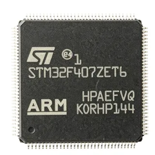
STM32F427ZIT6 - 180MHz ARM Cortex-M4F MCU, 2MB Flash | STMicroelectronics
MPN: STM32F427ZIT6 ✓ Active| Qty | Unit Price | Extended |
|---|---|---|
| 1 | $12.5 | $12.50 |
| 10 | $11.2 | $112.00 |
| 100 | $9.8 | $980.00 |
| 500 | $8.9 | $4,450.00 |
| 1,000 | $8.1 | $8,100.00 |
STM32F427ZIT6 Overview
A microcontroller (MCU) is a compact integrated circuit designed to govern a specific operation in an embedded system. It contains a processor core, memory (Flash and SRAM), and programmable input/output peripherals. The STM32F427ZIT6 belongs to the STM32F4 family, which is part of the broader STM32 32-bit ARM Cortex-M microcontroller portfolio. This family is known for its balance of performance, power efficiency, and rich peripheral integration, making it a popular choice for industrial, consumer, and IoT applications.
Key features include a 180 MHz ARM Cortex-M4F core with FPU and DSP instructions, 2 MB of dual-bank Flash memory, 256 KB of SRAM, and a comprehensive set of peripherals: 3x 12-bit ADCs, 2x 12-bit DACs, 8x UARTs, 6x SPIs, 3x I2Cs, 2x CAN, 1x USB 2.0 OTG FS/HS, 1x Ethernet MAC, and a camera interface. The device also includes a true random number generator (RNG), a cryptographic acceleration cell (AES, DES, 3DES), and a Chrom-ART Accelerator for 2D graphics.
The STM32F427ZIT6 is built on a 90nm process technology, offering a good balance between performance and power consumption. It features a flexible power management system with multiple low-power modes (Sleep, Stop, Standby) and a backup domain for RTC and SRAM retention. The dual-bank Flash allows read-while-write operations, enabling firmware updates without halting the system. The Chrom-ART Accelerator offloads 2D graphics operations from the CPU, improving GUI performance in display applications.
Typical applications include industrial control systems, motor drives, medical devices, consumer electronics, IoT gateways, and human-machine interfaces (HMI). The rich connectivity options (Ethernet, USB, CAN) make it suitable for networked embedded systems. The high Flash and SRAM capacities support complex firmware and real-time operating systems (RTOS).
When designing with this device, pay attention to the power supply decoupling: place 100nF capacitors close to each VDD pin and a 4.7uF bulk capacitor. The VDDA pin must be connected to a clean analog supply to ensure ADC accuracy. For high-speed USB and Ethernet, use the recommended external PHY and crystal oscillator (25 MHz for Ethernet).
Drop-in alternatives for STM32F427ZIT6 — same package, pin-to-pin compatible. Different-package parts requiring PCB rework are excluded.
Variants in this series
Same-series models that are drop-in compatible with STM32F427ZIT6 (same form factor and footprint) — differing in Core, Supply Voltage, Flash Memory, SRAM, Package.
Quick Comparison Tool — Select alternative parts for side-by-side comparison:
STM32F427ZGT6
✅ Drop-In ⚠️ 参数待验证📋 Reference alternative (not in catalog)
STM32F437ZIT6
✅ Drop-In ⚠️ 参数待验证✓ In Stock
$8.1 / Unit
View Datasheet →STM32F407ZIT6
✅ Drop-In ⚠️ 参数待验证📋 Reference alternative (not in catalog)
STM32F429ZIT6
✅ Drop-In ⚠️ 参数待验证✓ In Stock
$9.9 / Unit
View Datasheet →STM32F427ZIT6 Maximum Ratings & Electrical Characteristics
| Core | ARM Cortex-M4F with FPU |
| Maximum Clock Speed | 180 MHz |
| Flash Memory | 2 MB (dual-bank) |
| SRAM | 256 KB |
| Supply Voltage | 1.8 V to 3.6 V |
| Operating Temperature | -40C to +85C |
| Package | LQFP144 (20x20 mm) |
| GPIO Pins | 114 |
| ADC | 3x 12-bit, up to 24 channels |
| DAC | 2x 12-bit |
| UART | 8 |
| SPI | 6 |
| I2C | 3 |
| CAN | 2 |
| USB | 1x OTG FS/HS |
| Ethernet | 1x MAC 10/100 |
| Timers | 12 (16-bit and 32-bit) |
| DMA | 2x DMA controllers with 16 streams |
| RNG | Yes |
| Crypto | AES, DES, 3DES |
| Chrom-ART Accelerator | Yes |
| RoHS | Compliant |
STM32F427ZIT6 Pin Configuration
| Pin 1 | PE2 — GPIO / FMC_A23 |
| Pin 2 | PE3 — GPIO / FMC_A19 |
| Pin 3 | PE4 — GPIO / FMC_A20 |
| Pin 4 | PE5 — GPIO / FMC_A21 |
| Pin 5 | PE6 — GPIO / FMC_A22 |
| Pin 6 | VBAT — Backup battery supply |
| Pin 7 | PC13 — GPIO / RTC_TAMP1 |
| Pin 8 | PC14 — GPIO / OSC32_IN |
| Pin 9 | PC15 — GPIO / OSC32_OUT |
| Pin 10 | PF0 — GPIO / FMC_A0 |
| Pin 11 | PF1 — GPIO / FMC_A1 |
| Pin 12 | PF2 — GPIO / FMC_A2 |
| Pin 13 | PF3 — GPIO / FMC_A3 |
| Pin 14 | PF4 — GPIO / FMC_A4 |
| Pin 15 | PF5 — GPIO / FMC_A5 |
| Pin 16 | VSS — Ground |
| Pin 17 | VDD — Power supply |
| Pin 18 | PF6 — GPIO / FMC_NWAIT |
| Pin 19 | PF7 — GPIO / FMC_NE1 |
| Pin 20 | PF8 — GPIO / FMC_NCE2 |
| Pin 21 | PF9 — GPIO / FMC_NCE3 |
| Pin 22 | PF10 — GPIO / FMC_NE2 |
| Pin 23 | PH0 — GPIO / OSC_IN |
| Pin 24 | PH1 — GPIO / OSC_OUT |
| Pin 25 | PH2 — GPIO / FMC_SDCKE0 |
| Pin 26 | PH3 — GPIO / FMC_SDNE0 |
| Pin 27 | PH4 — GPIO / FMC_SDNE1 |
| Pin 28 | PH5 — GPIO / FMC_SDNWE |
| Pin 29 | PH6 — GPIO / FMC_SDNE1 |
| Pin 30 | PH7 — GPIO / FMC_SDCKE1 |
| Pin 31 | PH8 — GPIO / FMC_D16 |
| Pin 32 | PH9 — GPIO / FMC_D17 |
| Pin 33 | PH10 — GPIO / FMC_D18 |
| Pin 34 | PH11 — GPIO / FMC_D19 |
| Pin 35 | PH12 — GPIO / FMC_D20 |
| Pin 36 | PH13 — GPIO / FMC_D21 |
| Pin 37 | PH14 — GPIO / FMC_D22 |
| Pin 38 | PH15 — GPIO / FMC_D23 |
| Pin 39 | VSS — Ground |
| Pin 40 | VDD — Power supply |
| Pin 41 | PD0 — GPIO / FMC_D2 |
| Pin 42 | PD1 — GPIO / FMC_D3 |
| Pin 43 | PD2 — GPIO / FMC_D0 |
| Pin 44 | PD3 — GPIO / FMC_CLK |
| Pin 45 | PD4 — GPIO / FMC_NOE |
| Pin 46 | PD5 — GPIO / FMC_NWE |
| Pin 47 | PD6 — GPIO / FMC_NWAIT |
| Pin 48 | PD7 — GPIO / FMC_NE1 |
| Pin 49 | PD8 — GPIO / USART3_TX |
| Pin 50 | PD9 — GPIO / USART3_RX |
| Pin 51 | PD10 — GPIO / USART3_CK |
| Pin 52 | PD11 — GPIO / USART3_CTS |
| Pin 53 | PD12 — GPIO / USART3_RTS |
| Pin 54 | PD13 — GPIO / USART3_DE |
| Pin 55 | PD14 — GPIO / FMC_D0 |
| Pin 56 | PD15 — GPIO / FMC_D1 |
| Pin 57 | VSS — Ground |
| Pin 58 | VDD — Power supply |
| Pin 59 | PC0 — GPIO / ADC123_IN10 |
| Pin 60 | PC1 — GPIO / ADC123_IN11 |
| Pin 61 | PC2 — GPIO / ADC123_IN12 |
| Pin 62 | PC3 — GPIO / ADC123_IN13 |
| Pin 63 | PC4 — GPIO / ADC12_IN14 |
| Pin 64 | PC5 — GPIO / ADC12_IN15 |
| Pin 65 | PB0 — GPIO / ADC12_IN8 |
| Pin 66 | PB1 — GPIO / ADC12_IN9 |
| Pin 67 | PB2 — GPIO / BOOT1 |
| Pin 68 | PB3 — GPIO / JTDO |
| Pin 69 | PB4 — GPIO / NJTRST |
| Pin 70 | PB5 — GPIO / I2C1_SMBA |
| Pin 71 | PB6 — GPIO / I2C1_SCL |
| Pin 72 | PB7 — GPIO / I2C1_SDA |
| Pin 73 | BOOT0 — Boot mode selection |
| Pin 74 | PB8 — GPIO / I2C1_SCL |
| Pin 75 | PB9 — GPIO / I2C1_SDA |
| Pin 76 | VSS — Ground |
| Pin 77 | VDD — Power supply |
| Pin 78 | PE7 — GPIO / FMC_D4 |
| Pin 79 | PE8 — GPIO / FMC_D5 |
| Pin 80 | PE9 — GPIO / FMC_D6 |
| Pin 81 | PE10 — GPIO / FMC_D7 |
| Pin 82 | PE11 — GPIO / FMC_D8 |
| Pin 83 | PE12 — GPIO / FMC_D9 |
| Pin 84 | PE13 — GPIO / FMC_D10 |
| Pin 85 | PE14 — GPIO / FMC_D11 |
| Pin 86 | PE15 — GPIO / FMC_D12 |
| Pin 87 | PB10 — GPIO / I2C2_SCL |
| Pin 88 | PB11 — GPIO / I2C2_SDA |
| Pin 89 | PB12 — GPIO / SPI2_NSS |
| Pin 90 | PB13 — GPIO / SPI2_SCK |
| Pin 91 | PB14 — GPIO / SPI2_MISO |
| Pin 92 | PB15 — GPIO / SPI2_MOSI |
| Pin 93 | PD8 — GPIO / USART3_TX |
| Pin 94 | PD9 — GPIO / USART3_RX |
| Pin 95 | PD10 — GPIO / USART3_CK |
| Pin 96 | PD11 — GPIO / USART3_CTS |
| Pin 97 | PD12 — GPIO / USART3_RTS |
| Pin 98 | PD13 — GPIO / USART3_DE |
| Pin 99 | PD14 — GPIO / FMC_D0 |
| Pin 100 | PD15 — GPIO / FMC_D1 |
| Pin 101 | VSS — Ground |
| Pin 102 | VDD — Power supply |
| Pin 103 | PC6 — GPIO / I2S2_MCK |
| Pin 104 | PC7 — GPIO / I2S3_MCK |
| Pin 105 | PC8 — GPIO / SDIO_D0 |
| Pin 106 | PC9 — GPIO / SDIO_D1 |
| Pin 107 | PA0 — GPIO / ADC123_IN0 |
| Pin 108 | PA1 — GPIO / ADC123_IN1 |
| Pin 109 | PA2 — GPIO / ADC123_IN2 |
| Pin 110 | PA3 — GPIO / ADC123_IN3 |
| Pin 111 | PA4 — GPIO / DAC_OUT1 |
| Pin 112 | PA5 — GPIO / DAC_OUT2 |
| Pin 113 | PA6 — GPIO / ADC12_IN6 |
| Pin 114 | PA7 — GPIO / ADC12_IN7 |
| Pin 115 | PA8 — GPIO / MCO1 |
| Pin 116 | PA9 — GPIO / USART1_TX |
| Pin 117 | PA10 — GPIO / USART1_RX |
| Pin 118 | PA11 — GPIO / USB_DM |
| Pin 119 | PA12 — GPIO / USB_DP |
| Pin 120 | PA13 — GPIO / SWDIO |
| Pin 121 | PA14 — GPIO / SWCLK |
| Pin 122 | PA15 — GPIO / JTDI |
| Pin 123 | VSS — Ground |
| Pin 124 | VDD — Power supply |
| Pin 125 | PC10 — GPIO / SDIO_D2 |
| Pin 126 | PC11 — GPIO / SDIO_D3 |
| Pin 127 | PC12 — GPIO / SDIO_CK |
| Pin 128 | PC13 — GPIO / RTC_TAMP1 |
| Pin 129 | PC14 — GPIO / OSC32_IN |
| Pin 130 | PC15 — GPIO / OSC32_OUT |
| Pin 131 | PF0 — GPIO / FMC_A0 |
| Pin 132 | PF1 — GPIO / FMC_A1 |
| Pin 133 | PF2 — GPIO / FMC_A2 |
| Pin 134 | PF3 — GPIO / FMC_A3 |
| Pin 135 | PF4 — GPIO / FMC_A4 |
| Pin 136 | PF5 — GPIO / FMC_A5 |
| Pin 137 | VSS — Ground |
| Pin 138 | VDD — Power supply |
| Pin 139 | PF6 — GPIO / FMC_NWAIT |
| Pin 140 | PF7 — GPIO / FMC_NE1 |
| Pin 141 | PF8 — GPIO / FMC_NCE2 |
| Pin 142 | PF9 — GPIO / FMC_NCE3 |
| Pin 143 | PF10 — GPIO / FMC_NE2 |
| Pin 144 | PH0 — GPIO / OSC_IN |
Typical Applications
STM32F427ZIT6 is suitable for 6 applications: Industrial Control Systems, IoT Gateways, Medical Devices, Consumer Electronics, Human-Machine Interface (HMI), Automotive Electronics.
Industrial Control Systems
The STM32F427ZIT6 is ideal for industrial control systems such as PLCs, motor drives, and robotics. Its 180 MHz Cortex-M4F core with FPU accelerates complex control algorithms like FOC (Field-Oriented Control) for brushless DC motors. The device features advanced timers (12 timers including 2x 32-bit) that generate precise PWM signals, and 3x 12-bit ADCs with up to 24 channels for accurate current and voltage sensing. The 2 MB Flash and 256 KB SRAM support complex firmware and real-time operating systems. The wide operating temperature range (-40°C to +85°C) and robust peripheral set (CAN, UART, SPI) make it suitable for harsh industrial environments. In a typical motor drive, the MCU reads encoder feedback via a timer input, executes the FOC algorithm, and outputs PWM to the gate driver, achieving high efficiency and smooth operation. The dual-bank Flash allows firmware updates without stopping the motor, minimizing downtime.
Recommended
IoT Gateways
The STM32F427ZIT6 is well-suited for IoT gateways that aggregate data from multiple sensors and communicate via Ethernet, Wi-Fi, or cellular. Its integrated Ethernet MAC (10/100) enables wired connectivity, while USB OTG FS/HS supports external modems or storage. The 2 MB Flash and 256 KB SRAM can host a full TCP/IP stack (e.g., lwIP) and MQTT broker. The cryptographic acceleration cell (AES, DES, 3DES) provides hardware-accelerated encryption for secure communication. The device can manage multiple UARTs, SPIs, and I2Cs to interface with various sensors and actuators. In a typical gateway, the MCU collects data from Zigbee or LoRa modules via UART, processes and encrypts it, then forwards it to the cloud via Ethernet. The low-power modes (Stop, Standby) help reduce energy consumption when idle. The Chrom-ART Accelerator can drive a local display for status monitoring.
Recommended
Medical Devices
The STM32F427ZIT6 is used in medical devices such as patient monitors, infusion pumps, and diagnostic equipment. Its high processing power enables real-time signal processing for ECG, EEG, and blood pressure monitoring. The 3x 12-bit ADCs with high resolution capture analog signals from sensors, while the FPU accelerates digital filtering algorithms. The device's reliability and long-term availability make it suitable for medical applications. The 2 MB Flash can store patient data and firmware, and the dual-bank architecture allows safe firmware updates. The low-power modes extend battery life in portable devices. In a patient monitor, the MCU reads ECG signals via an analog front-end, processes them to detect arrhythmias, and displays the waveform on an LCD. The cryptographic cell can secure patient data for transmission. The device meets medical safety standards when properly designed with isolation and EMC protection.
Recommended
Consumer Electronics
The STM32F427ZIT6 powers consumer electronics like smart home hubs, wearable devices, and audio equipment. Its Chrom-ART Accelerator enhances GUI performance on TFT displays, making it ideal for smart home control panels. The device supports multiple connectivity options (USB, Ethernet, CAN) for seamless integration with other smart devices. The 2 MB Flash and 256 KB SRAM handle complex user interfaces and audio processing. The FPU and DSP instructions enable real-time audio effects and voice recognition. In a smart speaker, the MCU processes audio from a microphone, performs keyword spotting, and streams audio to a cloud service via Wi-Fi (using an external module). The low-power modes help conserve energy in battery-powered wearables. The device's rich peripheral set allows interfacing with touch sensors, LEDs, and displays.
Recommended
Human-Machine Interface (HMI)
The STM32F427ZIT6 is an excellent choice for HMI applications such as industrial control panels, home automation touchscreens, and point-of-sale terminals. The Chrom-ART Accelerator offloads 2D graphics operations from the CPU, enabling smooth rendering of complex GUIs on TFT-LCD displays. The device supports external SDRAM (via FMC) for larger frame buffers, and the 2 MB Flash can store graphical assets. The rich peripheral set includes touch controller interfaces (I2C/SPI), UARTs for communication with host systems, and Ethernet for remote monitoring. In a typical HMI, the MCU reads touch input, updates the display, and communicates with a PLC via Modbus over UART. The high clock speed ensures responsive user interaction. The device's low-power modes help reduce heat and energy consumption in enclosed panels.
Recommended
Automotive Electronics
The STM32F427ZIT6 is used in automotive applications such as body control modules, infotainment systems, and advanced driver-assistance systems (ADAS). Its high performance and rich connectivity (CAN, Ethernet, USB) make it suitable for in-vehicle networking. The device operates over the automotive temperature range (-40°C to +125°C for some variants, but this standard version is -40°C to +85°C; for automotive grade, consider the STM32F427ZIT6Q). The cryptographic cell secures communication between ECUs. The 2 MB Flash and 256 KB SRAM support complex algorithms for sensor fusion and diagnostics. In a body control module, the MCU manages lighting, windows, and door locks via CAN bus. The FPU accelerates signal processing for radar or camera data in ADAS. The device's robustness and long-term availability meet automotive quality standards.
Recommended
Recommended Products Summary
Engineering reference data for STM32F427ZIT6 — comparison, design guidance, and compliance information.
Selection Guide
Comparison with Alternatives
| Parameter | This Product | STM32F427ZGT6 | STM32F437ZIT6 | STM32F407ZIT6 | STM32F429ZIT6 |
|---|---|---|---|---|---|
| Package | LQFP144 | LQFP144 | LQFP144 | LQFP144 | LQFP144 |
| Brand | STMicroelectronics | STMicroelectronics | STMicroelectronics | STMicroelectronics | STMicroelectronics |
| Core Clock | 180 MHz | 180 MHz | 180 MHz | 168 MHz | 180 MHz |
| Flash Memory | 2 MB | 1 MB | 2 MB | 1 MB | 2 MB |
| SRAM | 256 KB | 192 KB | 256 KB | 192 KB | 256 KB |
| Chrom-ART Accelerator | Yes | Yes | Yes | No | Yes |
| TFT-LCD Controller | No | No | Yes | No | Yes |
| Crypto Acceleration | Yes | Yes | Yes | No | Yes |
| Price (1pc) | $12.50 | $11.80 | $13.20 | $9.50 | $13.00 |
Key Differentiators
- Higher clock speed and more SRAM than STM32F407ZIT6 (vs STM32F407ZIT6)
- Chrom-ART Accelerator for 2D graphics (vs STM32F407ZIT6)
- Cryptographic acceleration for secure communication (vs STM32F407ZIT6)
Design Notes
Decouple each VDD pin with a 100nF ceramic capacitor placed as close to the pin as possible. Additionally, place a 4.7uF bulk capacitor on the main supply. The VDDA pin must be connected to a clean analog supply (e.g., through a ferrite bead) and decoupled with a 1uF capacitor to ensure ADC accuracy. The VREF+ pin should be connected to a stable reference voltage for precise ADC conversions.
For high-speed interfaces like USB and Ethernet, follow the layout guidelines in the STM32F427xx reference manual (RM0090). Use controlled impedance traces for USB D+/D- (90 ohms differential) and Ethernet (100 ohms differential). Keep the 25 MHz crystal for Ethernet close to the PHY, and the 8 MHz HSE crystal close to the MCU with proper load capacitors. Ensure a solid ground plane under the MCU and all high-speed traces.
Do not exceed the absolute maximum ratings: VDD must not exceed 3.6V, and any pin voltage must not exceed VDD+0.3V. Ensure the BOOT0 pin is properly configured to select the desired boot mode (Flash, SRAM, or system memory). For firmware updates, use the dual-bank Flash feature to enable read-while-write, but ensure the bootloader handles bank switching correctly. Also, note that the STM32F427ZIT6 is not AEC-Q100 qualified; for automotive applications, use the 'Q' suffix variant (e.g., STM32F427ZIT6Q).
Compliance Information
RoHS compliant per STMicroelectronics. Not AEC-Q100 qualified; use 'Q' suffix for automotive. REACH compliant.