電源管理
サブカテゴリ
製品 (2770)

UCC21550Q-Q1 - 4A/6A Isolated Dual Gate Driver | TI
The Texas Instruments UCC21550Q-Q1 belongs to the UCC21550-Q1 automotive family of reinforced isolated dual-channel gate drivers with programmable dead time, delivering 4A peak-source and 6A peak-sink output current to drive power MOSFET, SiC, GaN, and IGBT transistors. It is offered in a 16-pin SOIC (DW) package rated at 5000Vrms reinforced isolation and an operating temperature range of -40C to 150C. An isolated gate driver is a power management IC that provides galvanic isolation between a low-voltage controller (such as an MCU) and the high-voltage power stage of a switching converter or motor inverter. Within the power-electronics hierarchy, it sits between the PWM controller and the power transistor, translating logic-level signals across the isolation barrier while providing the high peak currents needed to rapidly charge and discharge transistor gates. Key features include a capacitive isolation architecture with high common-mode transient immunity for fast-switching WBG devices, programmable dead time via a single resistor for half-bridge configurations, and flexible configuration as two low-side, two high-side, or one half-bridge driver. A disable pin and interlock function prevent shoot-through. Per TI product data, the family supports both A and B grade options with different propagation delay specifications. The driver uses TI capacitor-based isolation technology, which avoids the aging characteristics of optocouplers and sustains high dV/dt events typical of SiC and GaN switching. High CMTI and fast propagation delay enable narrow dead times, improving converter efficiency in high-frequency designs. Typical applications include on-board chargers and traction inverters in electric vehicles, solar string inverters, industrial motor drives, server and telecom power supplies, and wireless charging power stages. Design consideration: program the dead-time resistor per the datasheet equation and keep the gate-drive loops short; verify thermal dissipation from gate-charge losses at your switching frequency before finalizing the layout.

UCC21551-Q1 - 4A/6A Dual-Channel Isolated Gate Driver | TI
The Texas Instruments UCC21551-Q1 is an automotive-grade, dual-channel reinforced-isolated gate driver delivering 4 A peak source and 6 A peak sink current, packaged in a 14-pin SOIC (DWK) with >5.3 mm channel-to-channel creepage. It targets high-voltage power MOSFET, SiC, and IGBT gate driving in 5000 Vrms isolated systems. The device supports input-side VCCI from 3 V to 5.5 V and per-channel VDDA/VDDB outputs up to 25 V, with a minimum 125 V/ns common-mode transient immunity (CMTI) across the capacitive isolation barrier. An isolated gate driver is a semiconductor that bridges a low-voltage controller (MCU, DSP, FPGA) and a high-voltage power transistor, providing level shifting, reinforced galvanic isolation (typically UL 1577 / VDE 0884-11 compliant), and the high peak currents needed to charge and discharge the gate capacitance of MOSFETs, SiC FETs, or IGBTs. Within the broader taxonomy, the UCC21551-Q1 belongs to the gate-driver IC family, which sits under power management semiconductors and functions as the critical interface between control logic and switching power stages in isolated converters and motor drives. Key functional features include programmable dead time to prevent shoot-through in half-bridge topologies, an enable pin for sequencing and fault management, dual-input logic with built-in deglitch filters, and undervoltage lockout (UVLO) on both VCCI and VDDA/VDDB rails. The driver is configurable as two low-side, two high-side, or one half-bridge channel, and supports input voltages up to 25 V per output channel relative to its local ground. Internally, the UCC21551-Q1 uses TI's capacitive-based isolation technology to transfer PWM signals across a 5 kVRMS reinforced barrier while rejecting fast common-mode transients. The 4 A source / 6 A sink asymmetrical drive strength is optimized for switching IGBTs and SiC FETs whose gate charge requires stronger pull-down to prevent parasitic turn-on from Miller capacitance. Typical applications include EV traction inverters and onboard chargers, industrial servo drives and solar inverters, telecom DC/DC converters using phase-shifted full-bridge or LLC topologies, and any system where a reinforced-isolation barrier between controller and power stage is mandatory for safety or regulatory compliance. Design tip: when driving SiC FETs at high dV/dt, place a small external gate resistor (typically 2-10 ohm) close to the driver output to dampen parasitic ringing, and ensure the PCB creepage between channels and from each channel to ground meets the application's pollution degree and working voltage requirements. This page synthesizes the TI datasheet, current distributor pricing as of 2026-10-15, AEC-Q100 compliance status, drop-in same-package alternatives, and practical PCB layout guidance not consolidated on any single manufacturer or distributor page.
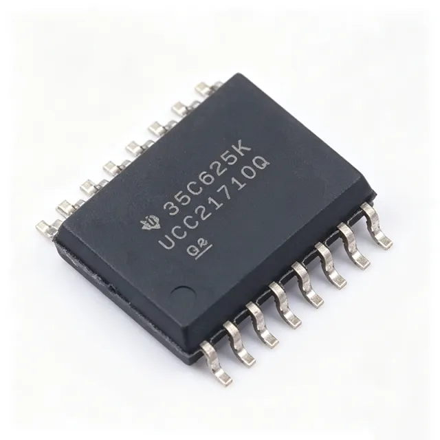
UCC21710-Q1 - 10A Isolated Gate Driver | Texas Instruments
The Texas Instruments UCC21710-Q1 is a galvanic isolated single-channel gate driver designed for high-power SiC MOSFETs and IGBTs up to 1700 V. It delivers up to ±10 A peak source and sink current in a 16-SOIC package, enabling fast switching of large power modules. The driver integrates reinforced isolation rated at 5700 Vrms, with high common-mode transient immunity (CMTI) for robust operation in noisy environments. A gate driver is a power-management IC that converts low-voltage control signals from a microcontroller into high-current pulses to drive the gate of power transistors. In a system hierarchy, the gate driver sits between the controller and the power switch, providing isolation and signal amplification. The UCC21710-Q1 belongs to the isolated gate driver family, which adds galvanic isolation to protect low-voltage control circuitry from high-voltage transients. Key features include: ±10 A peak source/sink current, 5700 Vrms reinforced isolation, single-channel operation, and input and output side UVLO. It supports overcurrent (OC) and short-circuit detection via shunt sensing, active Miller clamp to prevent spurious turn-on, fault reporting, and isolated analog-to-PWM sensing for temperature or voltage monitoring. These features provide comprehensive protection for SiC and IGBT switching. The UCC21710-Q1 uses capacitive coupling for signal transfer, achieving high CMTI. It is AEC-Q100 qualified for automotive applications, meeting the reliability demands of HEV/EV traction inverters. The device's short-circuit clamping feature limits gate voltage to slightly above VDD, protecting semiconductors from gate-source/emitter overvoltage breakdown. Typical applications include HEV/EV traction inverters, solar inverters, industrial motor drives, UPS, wind turbine converters, and railway traction. The high peak current and 1700-V rating allow it to directly drive large IGBT modules and SiC MOSFETs without external buffers. Its isolation enables safe operation in high-voltage DC-link systems. When designing with this device, ensure proper bias supplies: UCC14240-Q1 is a recommended isolated power supply for the output side. Pay attention to gate loop inductance and maintain adequate PCB spacing for reinforced isolation. The active Miller clamp must be connected to the gate to prevent high dV/dt-induced turn-on.
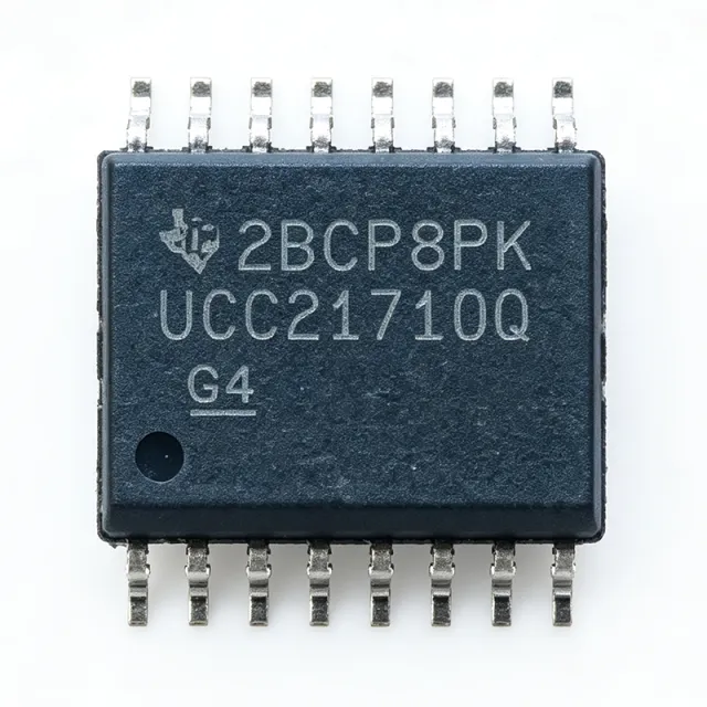
UCC21710QDWRQ1 - ±10A Isolated Gate Driver | TI | Automotive
The Texas Instruments UCC21710QDWRQ1 is an automotive-grade, galvanically isolated single-channel gate driver designed to switch up to 1700V SiC MOSFETs and IGBTs. The part delivers ±10A peak source/sink drive current, 5.7kVrms reinforced isolation, and high common-mode transient immunity (CMTI) in a 16-pin SOIC (DW) wide-body package. It is AEC-Q100 qualified and rated for -40C to +150C ambient operation, making it suitable for under-hood automotive power electronics. A gate driver is a power amplifier that accepts a low-power control signal from a microcontroller, DSP, or FPGA and produces the high-current drive required to efficiently switch power transistors such as IGBTs and SiC MOSFETs. In the power-conversion signal chain, the gate driver sits between the low-voltage control stage and the high-voltage power stage. Isolated gate drivers add galvanic isolation to protect low-voltage control circuitry from high-voltage transients, ground loops, and dv/dt noise, which is essential in traction inverters, motor drives, onboard chargers, and industrial converters. They sit hierarchically under gate driver -> driver IC -> power management IC -> semiconductor. Key features include fast DESAT overcurrent and short-circuit protection with shunt current sensing, fault reporting via FLT/EN, an active Miller clamp to prevent parasitic re-turn-on during high dv/dt events, and input/output side power supply UVLO. An integrated isolated analog-to-PWM sensor enables temperature or high-side voltage sensing across the isolation barrier without a discrete digital isolator. The device supports up to 1.5kVrms working voltage, a 12.8V to 18V output supply range, a typical propagation delay of 60ns, and CMTI of 100V/ns. The UCC21710QDWRQ1 uses TI's SiO2 capacitive isolation technology, which provides reliable reinforced isolation and high-speed signal transfer. Its advanced protection features optimize SiC and IGBT switching behavior, reducing switching losses and enhancing system robustness. The fast DESAT fault response (typically sub-microsecond) protects the power stage from catastrophic short-circuit events, while the soft turn-off (STO) sequence limits inrush and dv/dt during fault clearing. Typical applications include EV traction inverters, onboard chargers (OBC), high-voltage DC-DC converters, motor drives, and industrial power supplies. The automotive-grade qualification and wide temperature range make it particularly well-suited for xEV powertrain systems where SiC MOSFETs are increasingly adopted for higher switching frequencies and efficiency. When designing with this part, ensure proper PCB layout with short, low-inductance gate drive loops and adequate creepage/clearance for the 5.7kVrms isolation rating. The DESAT protection requires an external high-voltage blocking diode and resistor network, and the shunt current sensing input should be filtered to avoid false triggering during normal switching transients. This page synthesizes distributor pricing from DigiKey and LCSC, drop-in alternatives within the same 16-SOIC wide-body footprint, and practical design notes for SiC/IGBT half-bridges not collected in a single place in the manufacturer datasheet.

UCC21732-Q1 - ±10A Isolated SiC/IGBT Gate Driver | TI
The Texas Instruments UCC21732-Q1 is a galvanic isolated single-channel gate driver designed for SiC MOSFETs and IGBTs up to 2121 V DC operating voltage, delivering up to ±10 A peak source and sink current. Housed in a 16-pin SOIC (DW) wide-body package with reinforced capacitive isolation, it provides best-in-class dynamic performance and advanced protection for traction inverter, on-board charger, and industrial power-conversion designs. An isolated gate driver is a semiconductor device that translates a low-voltage PWM command from a controller into a high-current drive signal referenced to the floating gate of a high-voltage power switch (IGBT, SiC MOSFET, GaN HEMT), while providing galvanic isolation between the low-voltage domain and the high-voltage switching node. Within the broader taxonomy, isolated gate drivers sit below MOSFET/IGBT drivers and above optocouplers or transformer-based gate-drive solutions in the power management IC hierarchy. Key features include 5.7 kV RMS reinforced isolation, >150 V/ns common-mode transient immunity (CMTI), integrated 2-level turn-off (STO) for short-circuit protection, and an analog sensing pin (AIN) for temperature or voltage monitoring. The driver supports both unipolar and bipolar gate-drive supplies and is qualified to AEC-Q100 for automotive applications. The UCC21732-Q1 uses TI's SiO2 capacitive isolation technology, delivering 12.8 kV PK surge immunity, longer than 40 years of isolation barrier life, and low part-to-part propagation skew. On-board protection includes DESAT detection, soft turn-off, undervoltage lockout (UVLO) on both VCC and VDD, and an open-drain fault flag for the controller. Typical applications include 800 V automotive traction inverters, EV on-board chargers (OBC), industrial servo drives, solar string inverters, and high-power DC fast-charging stations. The high CMTI and 900 mA soft-turn-off current make it well suited to high-switching-speed SiC FETs where dv/dt noise can otherwise corrupt the gate signal. When designing with this driver, place the bootstrap or isolated supply decoupling capacitors as close to the VCC/VEE/VB/VS pins as possible and keep the DESAT and AIN traces short to avoid false triggering. Choose external gate resistors to balance switching loss and EMI. This page synthesizes manufacturer datasheet parameters, distributor pricing, drop-in alternatives, and practical design notes not collated in the original TI datasheet PDF.
UCC21739QDWRQ1 - 10A Isolated SiC/IGBT Gate Driver | TI
The Texas Instruments UCC21739QDWRQ1 is an automotive-qualified, galvanically isolated single-channel gate driver rated for ±10 A peak source/sink current, designed to drive SiC MOSFETs and IGBTs up to 990 V DC with high common-mode transient immunity (CMTI) and integrated analog sensing. Housed in a 16-pin SOIC (DWR) wide-body package with 3 kV RMS isolation, it combines SiO2 capacitive isolation technology with advanced active protection including DESAT detection, soft turn-off, and isolated analog temperature/voltage feedback. An isolated gate driver is a semiconductor device that transmits gate-drive control signals across an isolation barrier while providing high drive current to rapidly switch power transistors. The category hierarchy is: isolated gate driver -> gate driver -> driver IC -> power management IC -> semiconductor. Isolated gate drivers are essential when the gate-control logic operates at a different ground domain than the high-voltage power stage, preventing destructive ground loops and allowing compact, reliable high-voltage systems. Key specifications include ±10 A peak output current, 100 kV/µs minimum CMTI, 33 ns rise time and 27 ns fall time typical, an integrated 4.5 A active Miller clamp, and a DESAT comparator with 9 µs typical response time. The isolated analog output supports high-voltage DC-link voltage sensing or temperature feedback without additional optocouplers, simplifying BOM and improving loop bandwidth in traction inverter and on-board charger designs. Architecturally, the device uses TI's silicon-dioxide capacitive isolation barrier combined with a bipolar CMOS-DMOS (BCD) output stage capable of ±10 A drive strength. An on-chip 4.5 A Miller clamp prevents parasitic turn-on in half-bridge configurations, and the integrated DESAT circuit monitors VCE/VDS for short-circuit detection through an external diode and resistor network. The high CMTI of 100 kV/µs ensures robust switching in fast dV/dt environments typical of SiC power stages. Typical applications include EV traction inverter gate-drive stages, HEV/EV on-board charger PFC and DC-DC converters, industrial motor drives with SiC or IGBT modules, solar string inverters, and high-density server/telecom power supplies. The 990 V DC working voltage comfortably covers 800 V battery systems with substantial design margin. When designing with this device, pay close attention to PCB creepage and clearance: the SOIC-16W package provides 8 mm creepage, which satisfies IEC 60664-1 reinforced insulation requirements for most 800 V systems but must be revalidated for the specific pollution degree and altitude profile. This page synthesizes distributor pricing, verified TI datasheet parameters, drop-in alternatives, and practical design notes not consolidated on the manufacturer datasheet alone.
UCC21750-Q1 - 10A Isolated SiC/IGBT Gate Driver | TI Automotive
The Texas Instruments UCC21750-Q1 is a galvanic isolated single-channel gate driver designed for SiC MOSFETs and IGBTs up to 2121-V DC operating voltage, delivering ±10-A peak source and sink current in a 16-pin SOIC (DW) wide-body package with 8.0 mm creepage and clearance. It uses SiO2 capacitive isolation rated at 5.7 kVrms reinforced isolation, supporting high-side floating supply up to 2121 VDC for driving high-voltage power switches in traction, renewable, and industrial inverters. A gate driver is a power-management IC that translates low-power PWM control signals from a microcontroller or DSP into the high-current gate charge/discharge pulses needed to switch a power transistor (MOSFET, IGBT, SiC, or GaN). Isolated gate drivers add galvanic isolation between the low-voltage control domain and the high-voltage power domain, enabling safe control of half-bridge and full-bridge topologies in motor drives, solar inverters, and on-board EV chargers. The UCC21750-Q1 sits in the isolated gate-driver sub-category of TI's Power Management portfolio. Key features of the UCC21750-Q1 include fast overcurrent and short-circuit detection with DESAT protection, shunt current-sensing support, fault reporting to the controller, an internal active Miller clamp to prevent parasitic turn-on, and input- and output-side power-supply UVLO. An isolated analog-to-PWM sensor eases temperature or voltage feedback without requiring an extra isolated channel. The high CMTI (>100 V/ns typical) ensures robust operation in fast-switching SiC designs where common-mode transients are severe. Architecturally, the device combines TI's capacitive-isolation technology with a robust gate-drive output stage capable of ±10 A peak drive current. The integrated 4-A internal active Miller clamp provides an additional low-impedance path during turn-off, suppressing dV/dt-induced gate ringing. Programmable DESAT blanking, soft turn-off after fault, and TTL-compatible inputs give designers precise control over SiC and IGBT switching behavior. Typical applications include electric-vehicle traction inverters, on-board EV chargers, solar string inverters, industrial motor drives, and high-density telecom/server power converters using SiC MOSFET power modules. The wide operating temperature range and AEC-Q100 qualification make it suitable for automotive-grade designs under ISO 26262 functional-safety considerations. When designing with the UCC21750-Q1, carefully observe PCB creepage and clearance for the 8.0 mm SOIC-16DW wide-body package, place the DESAT resistor and blanking capacitor close to the IC, and use a Kelvin return path for the gate to avoid ground-bounce issues at high dV/dt. The internal active Miller clamp reduces external BOM but must still be verified against worst-case dV/dt conditions in the specific power module. This page synthesizes TI datasheet specifications, distributor pricing, drop-in alternatives and practical design notes not collated in any single manufacturer document.
UCC21750DW - ±10A 5.7kVrms Isolated SiC/IGBT Gate Driver | TI
The Texas Instruments UCC21750DW is a single-channel isolated gate driver for SiC MOSFETs and IGBTs, providing ±10 A peak source/sink drive current and 5.7 kVrms reinforced isolation in a 16-pin SOIC (DW) package. It supports DC link operating voltages up to 2121 V and integrates DESAT short-circuit protection, internal Miller clamp, and isolated analog sensing for temperature or high-voltage DC-bus feedback. A gate driver for SiC/IGBT is a galvanically isolated amplifier that translates low-voltage PWM logic from a controller into the high-current, high-voltage drive signals required to switch wide-bandgap power devices. Within the power-conversion hierarchy, it sits between the digital controller (DSP/MCU) and the power stage, providing level shifting, isolation barrier crossing, and protection functions that the controller cannot perform directly. Isolated gate drivers are essential in traction inverters, on-board chargers, industrial motor drives, and solar/string inverters where the low-voltage domain must remain safely isolated from the switching node at hundreds of volts. Key features include ±10 A peak output drive, 150 V/ns common-mode transient immunity (CMTI), integrated DESAT with programmable threshold, internal Miller clamp, isolated analog output for VCE/VDS or temperature sensing, soft-turn-off during fault, and under-voltage lockout (UVLO) for both primary and secondary sides. The device operates from -40 °C to +125 °C and is offered in a wide-body SOIC-16 (DW) package that meets IEC 60747-17 reinforced isolation standards. The architecture uses TI's capacitive isolation technology with a SiO2 dielectric barrier, achieving 5.7 kVrms isolation and >100 kV/us CMTI. The driver includes separate source and sink outputs, allowing independent turn-on/turn-off impedance tuning with external gate resistors for EMI and switching-loss optimization. An internal Miller clamp FET prevents parasitic turn-on caused by high dV/dt transients across the gate-drain capacitance of the power switch. Typical applications include EV traction inverters (SiC MOSFET drive up to 800 V bus), on-board chargers and DC fast chargers, industrial servo and AC drives, solar central/string inverters, and solid-state transformers. The wide UVLO range and reinforced isolation make the UCC21750DW particularly well suited to high-reliability industrial and automotive functional-safety applications. When designing with this device, place the decoupling capacitors as close as possible to VCC and VEE pins and minimize the gate-driver loop inductance to below 5 nH for clean switching at high dV/dt. Use a DESAT blanking capacitor selected per the datasheet equations to avoid nuisance trips on SiC devices with fast turn-on. This page synthesizes distributor pricing, drop-in alternatives, and practical design notes that supplement the manufacturer datasheet with cross-brand equivalents and AI-search-ready FAQ content.

UCC23513BQDWYQ1 - 4A/5A 5.7kVrms Isolated Gate Driver SOIC-6 | TI
The Texas Instruments UCC23513BQDWYQ1 is an automotive-qualified, 5.7-kVRMS reinforced-isolation single-channel isolated gate driver in a 6-pin SOIC (DWY) package, delivering 4 A source / 5 A sink peak drive current and featuring 8 V/12 V UVLO options. It is designed as a pin-to-pin compatible upgrade to opto-coupled gate drivers in IGBT and SiC/Si MOSFET drive applications. The driver integrates TI's capacitive isolation technology, providing 5.7 kVRMS reinforced isolation with surge capability up to 12.8 kV, while eliminating the LED aging and CTR degradation inherent to optocouplers. An isolated gate driver is a critical signal-conditioning and level-shifting IC that sits between a low-voltage microcontroller or DSP and a high-voltage, high-current power switch (IGBT, SiC MOSFET, or GaN FET). It performs three essential functions: galvanic isolation for high-voltage safety, level shifting from logic-level PWM inputs to gate-drive voltages, and current amplification to charge and discharge the large gate capacitance of power switches within tens of nanoseconds. UCC23513BQDWYQ1 falls within the isolated gate driver category of the power management IC hierarchy, addressing automotive motor drive, traction inverter, and industrial power-conversion designs. Key features include a wide driver supply range of up to 33 V, common-mode transient immunity (CMTI) of >100 kV/µs, and propagation delay of <100 ns with tight part-to-part matching for synchronous rectification. The Q1 suffix confirms AEC-Q100 qualification for automotive applications, and the SOIC-6 (DWY) wide-body package provides the necessary creepage and clearance for reinforced isolation. Integrated protection features include input-to-output isolation, undervoltage lockout, and thermal shutdown. The capacitive isolation barrier uses TI's proprietary silicon-dioxide-based high-voltage capacitor technology, achieving >100 kV/µs CMTI which prevents false triggering in high dV/dt switching environments. This makes the part particularly suited to SiC MOSFET drives where edge rates exceed 50 kV/µs. The driver accepts CMOS/TTL inputs and supports both 8 V and 12 V UVLO options for direct drive of IGBTs (12 V gate) and SiC MOSFETs (with 8 V option for negative gate bias designs). Typical applications include automotive traction inverters, on-board chargers, DC fast-charging stations, industrial motor drives, solar inverters, and UPS systems. The reinforced isolation makes it suitable for drives operating above 600 V with safety-critical isolation requirements per IEC 61800-5-1. When designing with this device, ensure that the gate-drive supply bypass uses 1 uF/X7R minimum close to VCC and that the gate resistor is sized to limit peak gate current below the 5 A sink rating. Layout creepage must be maintained per IEC 60664-1 for the SOIC-6 wide-body footprint. This page synthesizes distributor pricing, drop-in alternatives, and practical design notes not found in the manufacturer datasheet.
UCC23513BQDWYRQ1 - 4.5A/5.3A Auto Isolated Gate Driver SOIC-6 | TI
The Texas Instruments UCC23513BQDWYRQ1 is an automotive-qualified (AEC-Q100) opto-compatible, single-channel reinforced isolated gate driver housed in a 6-pin SOIC package (DWY). It delivers 4.5 A peak source current and 5.3 A peak sink current, with a 5.7 kV RMS reinforced isolation rating that meets the requirements of IEC 60747-17 reinforced isolation standards. The driver operates from a wide 9.5 V to 33 V supply range, making it suitable for IGBT, power MOSFET, and SiC MOSFET gate drive applications. An isolated gate driver is a critical component in power electronics, providing galvanic isolation between low-voltage control logic and high-voltage power switching devices. Gate drivers fall within the broader category of power management and driver ICs, serving as the interface between microcontrollers, DSPs, or gate-driver controllers and the high-current gates of IGBTs, MOSFETs, and SiC FETs. The UCC23513BQDWYRQ1 uses TI's proprietary capacitive isolation technology to achieve 5.7 kV RMS reinforced isolation with low propagation delay and high common-mode transient immunity, making it functionally pin-compatible with traditional opto-isolated gate drivers while delivering superior reliability and temperature performance. Key features include 4.5 A source / 5.3 A sink peak output current, 105 ns typical propagation delay, 35 ns part-to-part delay matching, 100 kV/us minimum common-mode transient immunity (CMTI), and 8 mm creepage/clearance package design. The device supports bipolar supply operation for driving IGBTs and SiC FETs requiring negative gate drive voltage. Its UVLO threshold of 8 V (typical) protects power switches against insufficient drive voltage. The wide operating temperature range of -40°C to +125°C suits automotive under-hood and industrial environments. Typical applications include automotive traction inverters, on-board chargers (OBC), DC fast charging stations, industrial motor drives, solar inverters, and server/telecom power supplies. Its opto-compatible input stage allows direct replacement of HCPL-3120-style optocouplers in existing designs without PCB changes, simplifying upgrades from older discrete isolator solutions to modern integrated gate drivers. When designing with this part, ensure that the local VCC bypass capacitance (typically 1 uF to 10 uF ceramic) is placed within 2 mm of the VCC pin. Account for the bootstrap supply current in high-side configurations, and never exceed the 33 V absolute maximum VCC rating. The driver's input is current-driven like an optocoupler, requiring the designer's choice of input LED current-limiting resistor. This page synthesizes distributor inventory, AEC-Q100 grade variants, drop-in alternatives, and practical design notes not found in the manufacturer datasheet alone, helping engineers select the right isolated gate driver for automotive and industrial applications.
UCC23513DWY - 4.5A/5.3A 5.7kVrms Isolated Gate Driver | TI
The Texas Instruments UCC23513DWY is a single-channel opto-compatible reinforced isolated gate driver delivering 4.5 A source and 5.3 A sink peak output current with 5.7 kVrms reinforced isolation, housed in a 6-pin SOIC (DWY) package with wide-body creepage. It is a pin-to-pin, drop-in upgrade for traditional opto-isolated gate drivers, replacing optocoupler-based designs with TI's capacitive isolation technology to eliminate aging-related CTR degradation. An isolated gate driver is a galvanically isolated amplifier that translates a low-voltage control logic signal (typically 3.3 V or 5 V from a microcontroller or DSP) into a high-current drive signal capable of switching a power semiconductor such as an IGBT, SiC MOSFET, or GaN FET. In the broader taxonomy, isolated gate drivers belong to the power management category between gate driver ICs and isolators, and the UCC23513 specifically combines both functions in a single package, providing reinforced isolation per IEC 60747-17 (certification to be confirmed) while driving the gates of high-voltage power devices in switch-mode power supplies and motor drives. Key features include a maximum 33 V output driver supply voltage, 8 V or 12 V VCC UVLO options, rail-to-rail output swing, 105 ns maximum propagation delay, 25 ns maximum part-to-part delay matching, 35 ns maximum pulse-width distortion, and 150 kV/µs minimum common-mode transient immunity (CMTI). The single-channel 6-SOIC package provides minimum 8.5 mm creepage and clearance suitable for reinforced isolation in industrial and renewable energy systems. The device uses TI's proprietary capacitive coupling isolation technology, replacing the LED/photodiode chain used in optocouplers. Compared to optocouplers, the UCC23513 offers superior temperature stability (no CTR drift over temperature or aging), lower propagation delay variation, and higher CMTI. The integrated 8 V or 12 V VCC UVLO with hysteresis protects SiC and IGBT power devices from partial-turn-on during startup. Typical applications include driving IGBTs in industrial motor drives, driving SiC MOSFETs in EV traction inverters and solar inverters, driving GaN FETs in telecom and server power, and replacing legacy optocoupler gate drivers in welding inverters and UPS systems. The wide VCC range supports both standard 15 V and emerging 12 V SiC/IGBT gate drive rails. When designing with the UCC23513DWY, place the VCC bypass capacitor directly at pins 5-6 with a 1 µF X7R ceramic or larger to handle peak gate charge currents. The driver side does not require isolated DC/DC bias - only a single VCC supply per channel is needed for the output stage; input side is powered directly from the controller side supply. This page synthesizes distributor pricing, drop-in alternatives, and practical design notes drawn from TI's UCC23513 datasheet and reference designs, providing engineering context not duplicated in the manufacturer documentation alone.

UCC25800-Q1 - Ultra-Low EMI Transformer Driver | Texas Instruments
The Texas Instruments UCC25800-Q1 is an ultra-low EMI transformer driver designed for isolated bias supplies in automotive and industrial applications. It integrates the switching power stage, control, and protection circuits into an 8-pin HVSSOP (DGN) package with an exposed thermal pad. The device operates from a wide input voltage range of 9 V to 34 V and delivers up to 9 W from a 34-V input. It uses an LLC resonant topology, which allows the use of transformers with higher leakage inductance but much smaller parasitic primary-to-secondary capacitance, significantly reducing common-mode EMI. A transformer driver is a power management IC that generates an AC voltage from a DC input to drive an isolation transformer, providing isolated DC outputs for gate drivers, sensors, and other bias supplies. It sits within the power management hierarchy: transformer driver -> isolated bias supply -> power management IC -> semiconductor. The UCC25800-Q1 simplifies isolated bias supply design by integrating the half-bridge power stage, oscillator, and protection features, eliminating the need for external high-side drivers and complex control loops. Key features include programmable switching frequency from 0.1 MHz to 1.2 MHz, enabling optimization for transformer size and EMI. The device offers a dedicated multi-function pin for external disabling and fault code reporting, enhancing system reliability. Its ultra-low EMI performance is achieved through the LLC topology and low interwinding capacitance transformer design, making it ideal for noise-sensitive automotive environments such as electric vehicles (EVs) and hybrid electric vehicles (HEVs). The UCC25800-Q1 integrates a high-efficiency half-bridge driver with adaptive dead-time control, reducing switching losses and improving efficiency. The device includes comprehensive protection features such as overcurrent protection, thermal shutdown, and undervoltage lockout (UVLO). The 8-pin DGN package with thermal pad provides excellent thermal handling, allowing operation at high ambient temperatures up to 125°C. Typical applications include isolated gate driver bias supplies for traction inverters, on-board chargers, DC-DC converters, and battery management systems in automotive. It is also suitable for industrial isolated power supplies, motor drives, and renewable energy systems. The wide input range and programmable frequency make it versatile for various power levels and isolation requirements. When designing with the UCC25800-Q1, ensure proper transformer selection with low interwinding capacitance to maximize EMI benefits. The SYNC pin allows external synchronization, but the external frequency must be set such that half the sync frequency is between 15% and 30% of the nominal frequency to maintain output regulation. Adequate input decoupling and a low-ESR output capacitor are essential for stable operation.

UCC27322DGN/DGNR - 9A Single LS MOSFET Driver w/ Enable | TI
The Texas Instruments UCC27322DGN/DGNR is a single-channel, 9 A peak low-side gate driver with split outputs and an active-high enable, offered in an 8-pin HVSSOP PowerPAD (DGN) package with an exposed thermal pad. It delivers 9 A source and 9 A sink drive current from a 4 V to 15 V supply, and uses TI's TrueDrive bipolar-CMOS output architecture to hold up at the Miller plateau of a power MOSFET. The DGN suffix denotes the tube-packed HVSSOP EP variant, while the DGNR suffix is the same die in a tape-and-reel packaging option. Typical rise/fall times of 20 ns into 1.8 nF load make it well suited to fast-switching power topologies. A low-side gate driver is a specialized power management IC that translates a low-current logic-level PWM signal from a controller into the high-current gate drive required to switch a power MOSFET or IGBT on the low side of a switching converter. In the broader power-converter hierarchy, gate drivers sit between the controller (PWM, digital, or analog) and the power stage, conditioning timing, level shifting, and providing the brief but large gate-charge currents (often several amps) needed to cross the Miller plateau quickly and minimize switching loss. Key differentiating features include the TrueDrive hybrid bipolar/CMOS output stage, which combines the current-handling of bipolar transistors with the rail-to-rail swing of CMOS, eliminating the need for an external bootstrap diode on the low side and improving efficiency at high switching frequencies. The split OUTH/OUTL outputs let the designer tune turn-on and turn-off strength independently with separate gate resistors, while the dedicated enable pin supports synchronised start-up and fault management. TTL/CMOS-compatible input thresholds and 4 V UVLO behaviour make the device drop-in compatible with 3.3 V and 5 V digital controllers. Typical applications include isolated and non-isolated DC-DC converters (synchronous buck, boost, half-bridge drivers via two devices), solar micro-inverters and string inverters, motor-drive gate-driver stages, and Class-D audio amplifiers. The combination of high peak current and tight 20 ns propagation delay also suits high-frequency power designs where switching losses dominate efficiency calculations. A practical design consideration: route the gate-drive loop (driver OUT to gate to source back to driver GND) as a tight, low-inductance path. Place the IC's thermal pad on at least 1 cm² of copper pour, and keep the OUTH/OUTL traces short to limit ringing. This page synthesises distributor pricing, drop-in alternatives, and practical design notes not found in the manufacturer datasheet alone.

UCC27322DGNR - 9A Single Low-Side MOSFET Driver | Texas Instruments
The Texas Instruments UCC27322DGNR is a single-channel, 9 A high-speed low-side gate driver with a non-inverting logic input, an enable pin, and split (separate source and sink) output stages, packaged in an 8-pin HVSSOP (DGN) PowerPAD package with thermal pad. Background knowledge: a low-side gate driver is a power-management IC that switches the gate of an N-channel MOSFET (or IGBT) between the source/ground rail and the gate-drive voltage. By sourcing and sinking high peak current into the gate capacitance, it dramatically reduces the Miller-plateau transition time versus driving the MOSFET directly from a logic output. Within the broader taxonomy, low-side gate drivers fall under gate-driver ICs -> MOSFET/IGBT drivers -> power management ICs -> semiconductors. The UCC27322 family specifically targets sub-20 V rails where a true low-side (ground-referenced) topology is acceptable. Key features include 9 A peak source and 9 A peak sink current using TI's TrueDrive mixed Bipolar/CMOS output stage, TTL/CMOS-compatible logic inputs, 4 V to 15 V VDD supply range, 20 ns typical rise/fall times into a 1.8 nF load, and an enable pin for sequential power-up. The split OUTH/OUTL pins allow independent tuning of turn-on and turn-off gate resistors - useful for EMI control and ringing management. The architecture uses TI's TrueDrive topology, which combines bipolar drive transistors with CMOS bias circuitry to deliver high peak current while avoiding the shoot-through losses of pure CMOS drivers. Internal hysteresis on the EN pin rejects false triggers from slow-rising MCU signals. Typical applications include switch-mode power supplies (synchronous-rectifier and primary-side MOSFET drive), motor-drive half-bridges for the low-side switch, solenoid and piezo-actuator drivers, and Class-D audio amplifier output stages. The wide supply range also makes it suitable for 12 V industrial systems. Design consideration: keep the gate-driver within 1 cm of the MOSFET gate pad to minimize parasitic loop inductance - high di/dt at 9 A peak can otherwise ring above the MOSFET VGS rating. Use independent turn-on and turn-off resistors on OUTH and OUTL for EMI tuning. This page synthesizes distributor pricing, verified drop-in alternatives from the UCC2732x/UCC3732x family, and practical PCB-layout design notes not found in the manufacturer datasheet alone.

UCC27511A - 4A/8A Low-Side Gate Driver | Texas Instruments
The Texas Instruments UCC27511A is a single-channel, high-speed low-side gate driver designed to drive MOSFETs, IGBTs, and emerging wide bandgap power devices such as GaN. It delivers 4-A peak source and 8-A peak sink currents, with a propagation delay of only 13 ns, making it suitable for high-frequency switching applications. The device operates from a 4.5-V to 18-V supply and features split outputs (OUTH and OUTL) for independent turn-on and turn-off control, as well as an enable pin with 5-V input handling capability. A low-side gate driver is a type of power management IC that amplifies control signals from a controller to efficiently switch a ground-referenced power transistor. It sits between the PWM controller and the gate of a MOSFET or IGBT, providing the high peak currents needed to charge and discharge the gate capacitance quickly. This reduces switching losses and improves efficiency in power converters. The UCC27511A belongs to the gate driver family, which is a subset of power management ICs essential for modern power electronics. Key features include a 13-ns propagation delay, 4-A source and 8-A sink peak currents, and a 5-V UVLO (undervoltage lockout) with hysteresis. The split outputs allow independent control of rise and fall times, enabling designers to optimize switching performance and reduce EMI. The device also features a robust design that minimizes shoot-through current, enhancing reliability in noisy environments. Technically, the UCC27511A uses a CMOS-based architecture that provides rail-to-rail output swing and high noise immunity. The input stage can handle 5-V logic signals directly, simplifying interface with microcontrollers and PWM controllers. The device is available in a SOT-23-6 package, which is compact and suitable for space-constrained designs. Typical applications include switch-mode power supplies, DC-to-DC converters, and companion gate-driver circuits for power modules. Its high-speed performance makes it ideal for synchronous rectification, active clamping, and other high-frequency topologies. When designing with the UCC27511A, ensure proper decoupling of the VDD pin with a 1-uF ceramic capacitor placed close to the device. The split outputs allow tuning of gate drive strength; use separate resistors on OUTH and OUTL to adjust rise and fall times independently.

UCC27517ADBVT - 4A/4A Single Low-Side Gate Driver | TI
The Texas Instruments UCC27517ADBVT is a single-channel, high-speed low-side gate driver IC delivering 4 A peak source and 4 A peak sink current in a 5-pin SOT-23 (DBV) package. It operates from a wide 4.5 V to 18 V VDD range with 5 V undervoltage lockout (UVLO) and handles negative input voltages down to -5 V at the IN/IN- pins, allowing reliable operation in noisy switching environments. A gate driver is a power-management IC that sits between a low-power controller (MCU, FPGA, analog PWM) and a high-power switching device (MOSFET, IGBT, GaN FET). Its job is to translate a logic-level command into a high-current drive signal that can rapidly charge and discharge the gate capacitance of the power switch. Within the broader hierarchy, the UCC27517ADBVT belongs to the gate-driver IC family, which sits under power management -> MOSFET/IGBT drivers -> low-side drivers -> single-channel drivers. Low-side drivers are the simplest and most common configuration; they switch the low-side FET in a half-bridge or a single-switch power topology. Key features of the UCC27517ADBVT include TTL/CMOS-compatible logic inputs that are independent of VDD, 13 ns typical propagation delay, 9 ns rise and 8 ns fall times into a 1 nF load, and a dual-input structure with one inverting and one non-inverting input (INA, INB) that can be tied together for a single-input configuration. The device is rated for operation across -40 C to +125 C and is qualified to 4 kV HBM ESD. Architecturally, the UCC27517ADBVT uses a paralleled output stage that sources and sinks high peak currents, holding shoot-through current low by design. The wide hysteresis between the high and low input thresholds gives excellent noise immunity, and the fixed (VDD-independent) input thresholds allow the same logic family to drive the gate from a controller powered by a different rail. Typical applications include driving MOSFETs and IGBTs in switch-mode power supplies, motor drive H-bridge low-side switches, Class-D audio amplifier output stages, and synchronous-rectifier FETs in DC-DC converters. Designers often choose this part when they need a compact, robust low-side driver that replaces discrete NPN/PNP totem-pole circuits. When designing with this part, place a 0.1 uF VDD bypass capacitor as close to pin 5 as possible and use a wider trace (>=20 mil) on the OUT pin to handle the 4 A peak pulses. Because the device can handle negative inputs, no extra input-protection diodes are needed in most bridge applications.
UCC27517AQDBVRQ1 - 4A/4A Automotive Low-Side Gate Driver | TI
The Texas Instruments UCC27517AQDBVRQ1 is an AEC-Q100 qualified single-channel high-speed low-side gate driver delivering 4-A peak source and 4-A peak sink current, with a VDD supply range up to 20 V and 4-V UVLO, housed in a 5-pin SOT-23-5 (DBV) package. A low-side gate driver is a power management IC that sits between a PWM controller or microcontroller and the gate of a MOSFET or IGBT, amplifying weak logic signals into the high peak currents needed to charge and discharge gate capacitance rapidly. Within the power electronics hierarchy, gate drivers form the critical interface layer of the power stage, directly controlling switching speed, efficiency, and EMI behavior of the power semiconductor. Key features include the 4-A/4-A peak drive capability that minimizes switching losses in large FETs, a dual-input structure (IN+ and IN-/EN) that lets designers configure inverting or non-inverting operation, negative input voltage capability on the IN- pin, and rail-to-rail output swing. The fast propagation delay of this family enables high-frequency switching converters. Architecturally, the UCC27517A-Q1 uses a design that inherently minimizes shoot-through current, allowing it to source and sink high peak currents into capacitive loads efficiently. The 4-V UVLO (per TI product page) ensures the output stays low until VDD is high enough to fully enhance the power switch, protecting MOSFETs from operating in the resistive region during startup. Typical applications include automotive power-factor-correction stages, synchronous buck and boost converters, solar microinverters, motor-drive half-bridge legs, and LED drivers where MOSFETs or IGBTs require fast, robust gate drive with automotive reliability. When designing with this part, place a low-ESR 0.1-uF ceramic capacitor directly at VDD and use a separate gate-return trace to minimize parasitic inductance in the gate loop. The dual-input pins allow polarity selection without extra inverters. This page synthesizes distributor listings, drop-in alternative analysis, and practical design notes not found in the manufacturer datasheet.

UCC27524AQDRQ1 - Dual 5A Low-Side Gate Driver, AEC-Q100 | TI
The Texas Instruments UCC27524AQDRQ1 is a dual-channel, high-speed, low-side gate driver IC delivering 5A source and 5A sink output current per channel, rated for VDD up to 20V, with 4V UVLO and direct -5V negative input voltage handling, housed in an 8-pin SOIC (D) surface-mount package qualified to AEC-Q100 for automotive use. A gate driver is a power management IC that bridges the low-voltage control domain (MCU or PWM controller outputs) and the high-power switching domain (MOSFET and IGBT gates). Within the hierarchy of power electronics, the low-side gate driver sits between the PWM controller and the power transistor, amplifying logic-level signals into high-peak-current gate pulses that charge and discharge the MOSFET gate capacitance quickly enough to minimize switching losses. The gate driver family therefore sits under power management ICs, alongside voltage regulators and motor drivers. Key features of the UCC27524AQDRQ1 include 5A/5A peak source/sink current, high-speed switching with fast rise and fall times suitable for high-frequency power converters, dual non-inverting channels with TTL/CMOS-compatible inputs, and tolerance of -5V directly on the input pins for robustness against switch-node ringing and negative spikes. According to the TI product page, the UCC27524A-Q1 is a variant of the UCC2752x family, adding negative input capability over the base UCC2752x parts. Architecturally, the device uses a bipolar/CMOS output stage that sinks current more strongly than it sources on the pulldown path, which helps hold the MOSFET gate low during Miller-plateau events and prevents dv/dt-induced turn-on. The dual-channel design drives two switches (for example, two paralleled FETs or two legs of a push-pull stage) from a single 8-pin IC, saving board space versus two single-channel drivers. Typical applications include automotive DC-DC converters, motor inverters, solar inverters, telecom and server power supplies, and class-D audio amplifier output stages - anywhere a PWM controller needs to switch MOSFETs or IGBTs at high frequency with low switching losses. A key design consideration: the SOIC-8 package's thermal and ground-path inductance limits practical peak performance, so placing the driver's ground pin and the MOSFET source on the same tight ground loop, with a local 0.1uF to 1uF VDD decoupling capacitor plus bulk capacitance, is essential to realize the full 5A peak current. This page synthesizes distributor pricing, drop-in alternatives, pinout data, and practical design notes not found in the manufacturer datasheet.

UCC2773x-Q1 - 700V Half-Bridge Gate Driver | TI Automotive
The UCC2773x-Q1 is a high-speed, automotive-grade 700V half-bridge gate driver from Texas Instruments, designed to drive power MOSFETs and IGBTs in half-bridge configurations. It provides 3.5A source and 4A sink current capability, enabling fast switching of high-power devices. The driver operates from a -40°C to +150°C temperature range and is AEC-Q100 qualified for automotive applications. A half-bridge gate driver is a specialized integrated circuit that provides the necessary voltage and current to switch the high-side and low-side transistors in a half-bridge topology. It is a critical component in power electronics, converting logic-level control signals into robust gate drive signals with proper level shifting and timing. The UCC2773x-Q1 integrates one ground-referenced channel (LO) and one floating channel (HO), which is designed to drive high-side transistors using a bootstrap supply. Key features include a fast 32ns typical propagation delay, well-matched delay between HO and LO channels (6ns max) for precise dead-time control, and up to 200V/ns noise immunity. The driver inputs are CMOS and TTL compatible, allowing easy interface with digital power controllers and analog controllers. Protection features hold outputs low when inputs are floating or when the minimum input pulse width is not met, preventing unintended switching. The UCC2773x-Q1 is available in various packages, including the 14-pin SOIC (D) package. Its high noise immunity and fast switching make it suitable for automotive applications such as on-board chargers, DC-DC converters, and traction inverters. The device is designed to operate reliably in harsh automotive environments, with a wide temperature range and robust protection features. Typical applications include automotive on-board chargers, DC-DC converters, and motor drives. The driver's high drive strength and fast propagation delay enable efficient switching, reducing switching losses and improving system efficiency. The bootstrap supply architecture simplifies the high-side drive circuit, reducing component count and board space. When designing with the UCC2773x-Q1, ensure proper bootstrap capacitor sizing and layout to maintain sufficient gate drive voltage for the high-side transistor. Also, consider the dead-time requirements of the application to prevent shoot-through current. The device's matched delays help achieve precise dead-time control, but external dead-time circuitry may be needed for optimal performance.

UCC28019ADR - 65kHz CCM PFC Controller | Texas Instruments
The Texas Instruments UCC28019ADR is an 8-pin active Power Factor Correction (PFC) controller using boost topology in Continuous Conduction Mode (CCM). Designed for systems from 100 W to over 2 kW with wide-range universal AC line input, it operates at a fixed 65-kHz frequency with a maximum duty cycle of 98% (typ). Start-up current during undervoltage lockout is below 200 uA, and low-power standby mode is entered by pulling the VSENSE pin below 0.77 V. The DR suffix denotes the 8-pin SOIC (D) package supplied in tape and reel. A PFC controller is a specialized power management IC that shapes the input current of an AC-DC power supply to be sinusoidal and in phase with input voltage, improving power factor and reducing harmonics to meet standards such as IEC 61000-3-2. In a boost PFC, the controller regulates the DC bus voltage while forcing input current to follow input voltage. PFC controllers belong to the broader family of switch-mode power supply control ICs within power management. Key features include the 8-pin solution that reduces external component count, wide-range universal AC input, fixed 65-kHz switching, output over/under voltage protection, open-loop protection, overcurrent protection, and enhanced start-up and transient response. Average current mode control delivers stability and noise immunity, supported by an internal reference, error amplifier, and PWM comparator. UVLO thresholds are 10.5 V on and 9.5 V off, with a maximum Vin of 21 V. Typical applications include desktop computer and server power supplies, telecom rectifiers, industrial power systems, LED lighting drivers, and battery chargers that must meet power quality regulations. The controller supports both sub-150 W and above-750 W application ranges. When designing with the UCC28019ADR, keep gate drive and current-sense paths short and low inductance, place the sense resistor near the IC with a Kelvin connection, and avoid accidental triggering of the 0.77 V VSENSE standby threshold during normal operation.

UCC28019AQDRQ1 - 65kHz CCM PFC Controller, AEC-Q100 | TI
The Texas Instruments UCC28019AQDRQ1 is an AEC-Q100 qualified 8-pin active Power Factor Correction (PFC) controller that uses boost topology operating in Continuous Conduction Mode (CCM) at a fixed 65 kHz switching frequency. It is suitable for systems from 100 W to greater than 2 kW over a wide-range universal AC line input, packaged in an 8-SOIC (D) surface-mount package. A PFC controller is a power management IC that shapes the input current of an AC-DC converter so it follows the sinusoidal line voltage, raising power factor and reducing harmonic distortion to meet IEC harmonic-current requirements. PFC pre-regulators sit between the bridge rectifier and downstream DC-DC stage in the broader power-supply hierarchy. Key features include an 8-pin solution that senses neither line voltage nor line frequency, reducing external component count; a maximum duty cycle of 97%; and start-up current below 200 uA during undervoltage lockout, minimizing startup loss. Low-power standby mode is controlled by pulling the VSENSE pin below 0.77 V, enabling efficient no-load and light-load system behavior. Internal protection includes soft start, open-loop detection, and overvoltage protection per the datasheet. Architecturally, the controller implements average-current-mode CCM control with soft, controlled on-times that reduce ripple current stress on the boost inductor and MOSFET compared with transition-mode approaches, making it well matched to higher-power designs where EMI filtering and peak-current stress dominate design cost. Typical applications include automotive onboard chargers and front-end AC-DC power supplies, telecom rectifiers, industrial power supplies in the several-hundred-watt to multi-kilowatt range, and server/storage front ends requiring high power factor over universal AC input. Design consideration: because the part operates in CCM, ensure the boost inductor is sized so inductor current remains continuous above minimum load, and add adequate slope compensation via the ICOMP network per the TI datasheet to avoid subharmonic oscillation.
UCC2808AQDR-1EP - 1A Push-Pull PWM Controller, 1MHz, 8-SOIC | TI
The Texas Instruments UCC2808AQDR-1EP is a BiCMOS, low-power, current-mode push-pull pulse-width modulator (PWM) housed in an 8-pin SOIC (D) package, qualified to Texas Instruments' "Enhanced Product" (EP) pedigree with extended temperature performance to 125°C and enhanced diminishing manufacturing sources (DMS) support. It integrates all control and drive circuitry required for off-line or DC-to-DC fixed-frequency current-mode switching power supplies, delivering dual 1A push-pull output stages that switch at half the oscillator frequency. A current-mode PWM controller is a type of switching power supply controller that regulates output voltage by directly controlling the peak inductor current each switching cycle, rather than only the duty cycle. The UCC2808AQDR-1EP belongs to the current-mode controller product family, sitting within the broader hierarchy of switching regulators -> DC-DC converters -> power management ICs -> semiconductors. Current-mode control provides inherent input-voltage feedforward, cycle-by-cycle current limiting, and simplified loop compensation compared to voltage-mode architectures, making it well-suited for both isolated and non-isolated topologies. Key features of this EP variant include a 1 MHz maximum switching frequency, 49% maximum duty cycle, 12.5V undervoltage lockout (UVLO) start-up threshold, dual 1A push-pull output drivers with active low assertion, and BiCMOS construction that reduces operating current versus bipolar predecessors. The EP designation additionally provides one assembly/test site, one fabrication site, qualification pedigree, and enhanced product-change notification for high-reliability applications. The internal oscillator is programmed via a single external resistor and capacitor pair, supporting flexible frequency design. Architecturally, the device combines a precision reference, error amplifier, current-sense comparator, and dual totem-pole output drivers on a single BiCMOS die. The push-pull output stage eliminates the need for an external gate-drive transformer in many half-bridge and full-bridge derived designs, while current-mode operation simplifies feedback loop design. The 8-pin SOIC footprint offers straightforward PCB integration in both retrofits and new converter layouts. Typical applications include industrial DC-DC converters, telecom isolated power modules, low-power offline auxiliary supplies, and battery-charging front-end stages. Designers often pair the controller with small MOSFETs or gate-driver transformers for 50W to 250W power levels, taking advantage of the high switching frequency to shrink magnetics and output filters. When designing with the UCC2808AQDR-1EP, place the timing RC components close to pins 6 and 7 to minimize noise pickup, and ensure the current-sense resistor connection to pin 2 is a short, kelvin-routed trace. The push-pull outputs require proper dead-time management by the external power stage to prevent shoot-through. This page consolidates distributor pricing, drop-in compatible variants across the same SOIC-8 footprint, and design notes specifically tailored to high-reliability push-pull converter implementations.
UCC28180 - 8-Pin CCM PFC Controller, 18-250 kHz | Texas Instruments
The Texas Instruments UCC28180 is an 8-pin active Power-Factor Correction (PFC) controller designed for continuous conduction mode (CCM) boost pre-regulators in AC-DC front-ends, with a programmable switching frequency range of 18 kHz to 250 kHz and housed in an 8-pin SOIC package. Key specifications per TI product documentation include CCM operation with input voltage support suitable for universal AC line (85 VAC to 265 VAC) and regulated DC output boost voltages typically targeting 390 V at 1 kW per the PMP22606 reference design. The device integrates a transconductance voltage amplifier for output voltage regulation, a current loop for sinusoidal line-current shaping, and programmable switching frequency set by an external resistor. A Power-Factor Correction (PFC) controller is the control IC that shapes the input current of an AC-DC converter to be in phase with the input voltage, raising the power factor toward unity and reducing harmonic distortion below regulatory limits (EN61000-3-2, JEITA-MITI). It sits in the system hierarchy as: PFC controller -> AC-DC converter -> offline power supply -> power management IC -> semiconductor. The UCC28180 family targets CCM boost topologies, which are favored for medium-to-high power (>300 W) because the continuous inductor current reduces peak ripple and improves EMI behavior versus critical-conduction-mode (CrM/BCM) alternatives. Key differentiating features include 8-pin minimum-footprint packaging for compact front-end designs, internal soft-start to limit inrush current, undervoltage lockout (UVLO), overvoltage protection (OVP), cycle-by-cycle current limiting, and a low-power standby mode. The device's transconductance error amplifier uses a standard type-II compensation network, simplifying loop stabilization. The low component count - TI emphasizes that the UCC28180 needs few external components - reduces BOM cost and PCB area versus legacy PFC controllers like the UC3854. Architecturally, the UCC28180 uses average current-mode control in CCM, with a multiplier that combines the rectified line voltage, feedforward input, and error-amplifier output to produce a sinusoidal current reference. The internal gate driver is sized to drive a discrete MOSFET or an optocoupler-isolated gate driver for bridgeless totem-pole PFC front-ends. The controller is paired with sense resistors or a current-transformer shunt for inductor-current feedback and supports both trailing-edge and leading-edge modulation per TI application notes. Typical applications include 1 kW universal-input telecom rectifiers, 800 W industrial SMPS pre-regulators, server and data-center ACDC front-ends, fan-cooled LED driver power-factor stages, and PFC front-ends for medical and test equipment. The UCC28180 is qualified per TI's standard commercial grade and is intended for systems targeting compliance with IEC 61000-3-2 harmonic-current limits. Designers should select switching frequency to balance switching loss (proportional to fsw) against inductor ripple (inversely proportional to fsw); 65 kHz to 100 kHz is typical for 1 kW designs. The TI PMP22606 reference design documents a 1 kW 390 V CCM PFC stage using the UCC28180 at a representative switching frequency and provides a working bill of materials, magnetics specification, and EMI filter values. This page synthesizes distributor pricing, available drop-in alternatives including same-package options from TI's UCC28xxx family, and practical CCM PFC design notes not found in the manufacturer datasheet alone.
UCC28600D - 8-Pin Quasi-Resonant Flyback Green-Mode Controller | TI
The Texas Instruments UCC28600D is an 8-pin quasi-resonant flyback green-mode PWM controller designed for energy-efficient offline AC-DC converters, packaged in an 8-pin SOIC (D) and supporting switching frequencies from 40 kHz to 130 kHz. What is a quasi-resonant flyback controller? A quasi-resonant flyback controller is a type of AC-DC PWM (pulse-width modulation) controller that switches the MOSFET at the valley of the drain-voltage waveform instead of at a fixed frequency. This valley-switching technique minimizes switching losses, reduces EMI, and improves energy-efficiency at light loads, making it a key building block of modern green-mode switch-mode power supplies (SMPS). Key features include built-in advanced energy-saving features, frequency fold-back and green-mode operation that reduces switching losses and standby power consumption, integrated high level protection features, and a wide VDD operating range. The controller integrates high-level protection features and supports quasi-resonant operation to meet stringent world-wide energy efficiency requirements. Technically, the UCC28600 incorporates frequency fold-back and green-mode operation to reduce switching losses and improve light-load efficiency. Its quasi-resonant detection circuit senses the transformer's drain voltage and triggers turn-on at the first valley, reducing dv/dt and EMI. Internal protection features typically include over-current protection (OCP), over-temperature protection, under-voltage lockout (UVLO), and over-voltage protection (OVP), making it a complete controller for cost-effective, energy-efficient flyback converters. Typical applications include AC-DC adapters and chargers for portable equipment, auxiliary and standby power supplies for desktop PCs and TVs, white goods and appliance power, set-top boxes, and industrial low-power offline converters. Quasi-resonant operation makes it especially well suited to designs targeting ENERGY STAR, DoE Level VI, and EU CoC Tier 2 efficiency standards. When designing with this device, the transformer's primary-side leakage inductance and the auxiliary VDD winding must be sized correctly to ensure the controller stays above its UVLO threshold under all load transients. Failure to maintain adequate VDD margin is the most common cause of UCC28600 start-up or hiccup-mode issues in production designs. This page synthesizes distributor pricing, drop-in alternatives, and practical design notes not found in the manufacturer datasheet to support your component selection, BOM risk assessment, and second-sourcing decisions.