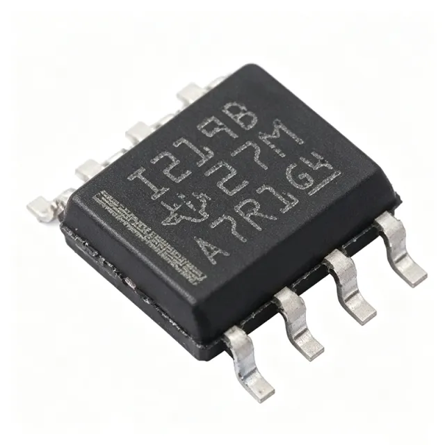
INA219BIDR - 26V 12-Bit I2C Power Monitor | Texas Instruments
部品番号: INA219BIDR ✓ 生産中| 数量 | 単価 | 小計 |
|---|---|---|
| 1 | $3.12 | $3.12 |
| 10 | $2.8 | $28.00 |
| 100 | $2.35 | $235.00 |
| 500 | $1.95 | $975.00 |
| 1,000 | $1.62 | $1,620.00 |
INA219BIDR 概要
A current shunt monitor measures the voltage drop across a sense resistor placed in series with a load. The INA219BIDR is a digital power monitor, a subtype of current shunt monitor that integrates an ADC and digital interface to report current, voltage, and power directly to a microcontroller, fitting the hierarchy: current shunt monitor -> power monitor -> analog front-end -> signal chain IC.
Key features include 16 programmable I2C addresses allowing up to 16 devices on one bus, programmable conversion times and filtering options, and a calibration register enabling direct readouts of current in amperes. An internal multiplier computes power on-chip, reducing host processor overhead. High-side sensing architecture monitors current without disturbing the ground path, critical for systems with shared grounds.
The device uses a zero-drift architecture to minimize input offset voltage and drift, ensuring accuracy over temperature and time. The 12-bit ADC provides fine shunt-voltage resolution, enabling precise current sensing with minimal shunt resistance and low power loss. The I2C interface supports standard and fast modes with SMBus compatibility for server environments.
Typical applications include server and telecom power management, battery chargers, embedded power supplies, test and measurement instruments, and industrial automation where accurate power telemetry is required. The 0 to 26 V bus range covers common 5 V, 12 V, and 24 V rails.
Design tip: place the shunt resistor in the high-side path, keep bus voltage within 0-26 V, and use the ALERT-capable configuration to flag overcurrent events. Proper supply decoupling and short, Kelvin-connected shunt traces are essential for full 0.5% accuracy. Pricing from major distributors as of 2026-08-30.
ドロップイン代替品: INA219BIDR — 同一パッケージでピン互換。PCBの作り直しが必要な異なるパッケージの部品は除外されています。
このシリーズのバリエーション
同一シリーズでドロップイン互換のモデル: INA219BIDR (同一形状・フットプリント) — 相違点: ADC Resolution, Function, Interface, Operating Temperature, Package.
クイック比較ツール — 並列比較する代替部品を選択:
INA219BID
✅ ドロップイン📋 参考代替品(カタログ未掲載)
INA219AIDR
✅ ドロップイン✓ 在庫あり
$1.05 / 個
データシートを見る →LTC6105CMS8
⚡ 同一パッケージ📋 参考代替品(カタログ未掲載)
INA219BIDR 仕様
| 機能 | Bidirectional current shunt and power monitor |
| インターフェース | I2C / SMBUS compatible |
| Bus Voltage Range | 0 V to 26 V |
| Supply Voltage Range | 3 V to 5.5 V |
| Supply Current (max) | 1 mA |
| ADC Resolution | 12 bit |
| Accuracy (INA219B grade) | 0.5% maximum over temperature |
| Number of Programmable Addresses | 16 |
| Reports | Current, voltage, and power |
| Sensing Architecture | High-side |
| Programmable Features | Conversion times and filtering options, calibration register |
| 動作温度 | -40C to +125C |
| パッケージ | 8-SOIC (3.90 mm width) |
| 実装タイプ | Surface Mount |
| Packaging | Tape & Reel (TR) |
| RoHS ステータス | Compliant |
| Lead Free Status | Lead Free |
INA219BIDR ピン構成
| ピン 1 | IN+ — Shunt positive input, connect to bus side of shunt resistor |
| ピン 2 | IN- — Shunt negative input, connect to load side of shunt resistor |
| ピン 3 | GND — Ground reference |
| ピン 4 | VS — Power supply, 3 V to 5.5 V |
| ピン 5 | SDA — I2C/SMBus data line |
| ピン 6 | SCL — I2C/SMBus clock line |
| ピン 7 | A0 — I2C address select bit 0 |
| ピン 8 | A1 — I2C address select bit 1 |
主な用途
INA219BIDR の用途: 6 件s: Server and Telecom Power Management, Battery Chargers and Battery-Powered Systems, Embedded Power Supplies and DC-DC Rail Monitoring, Industrial Automation and Motor Control Telemetry, Test and Measurement Instruments, IoT and Smart-Home Power Profiling.
Server and Telecom Power Management
The INA219BIDR fits server and telecom rail monitoring because its SMBus-compatible interface and 16 programmable addresses let up to 16 devices share one 2-wire bus across multiple 12 V and 5 V rails within the 0-26 V bus range. Placed in the high-side shunt path with a calibration register set for the chosen sense resistor, it reports amperes and watts directly, offloading computation from the baseboard management controller. Its 0.5% B-grade accuracy and programmable filtering give reliable telemetry for power budgeting and hot-swap supervision.
おすすめ
Battery Chargers and Battery-Powered Systems
For battery charging, the INA219BIDR senses charge and discharge current bidirectionally in the high-side path, preserving a clean ground reference for the charging IC and fuel gauge. The 12-bit ADC resolves small shunt drops so a low-value shunt minimizes power loss, extending runtime. Its 3-5.5 V supply and 1 mA maximum consumption suit portable designs, while the programmable conversion time and averaging let the firmware trade update rate against noise, tracking charge termination current accurately across 0-26 V packs.
おすすめ
Embedded Power Supplies and DC-DC Rail Monitoring
Embedded systems use the INA219BIDR to digitize rail current and voltage for fault detection and power profiling. Inserted between a DC-DC converter output and its load, the device monitors 0-26 V buses, covering 3.3 V, 5 V, 12 V, and 24 V rails. The internal multiplier computes power without host overhead, and the calibration register converts shunt readings to amperes directly. The zero-drift architecture maintains accuracy over temperature, and the 16-address I2C bus scales to multi-rail designs with a single MCU port.
おすすめ
Industrial Automation and Motor Control Telemetry
Industrial equipment requires power telemetry on 24 V buses, squarely inside the 0-26 V measurement window of the INA219BIDR. High-side sensing avoids ground disturbances in noisy motor environments, and the programmable filtering suppresses PWM ripple before ADC conversion. The B-grade 0.5% accuracy over -40C to +125C supports condition monitoring and energy accounting in factories. Firmware can poll current, voltage, and power registers over I2C to trend motor load and detect stalls or overload conditions early.
おすすめ
Test and Measurement Instruments
Bench instruments and USB power analyzers use the INA219BIDR as a digital ammeter/wattmeter front-end. The 12-bit ADC with programmable conversion time lets instruments select fast sampling for transients or heavy averaging for precision readings, while 0.5% B-grade accuracy provides trustworthy loggable data. The device reports shunt voltage, bus voltage, and computed power over I2C, so a small MCU can present readings on a display or USB link. Its SOIC-8 footprint fits compact dongle-style measurement adapters on 0-26 V buses.
おすすめ
IoT and Smart-Home Power Profiling
IoT nodes benefit from the INA219BIDR's 1 mA maximum supply draw and 3-5.5 V operation, letting it stay powered continuously to profile device energy consumption. Placed in the high-side of a 5 V or 12 V rail, it streams current, voltage, and power over I2C to an ESP/MCU-class hub, enabling energy dashboards and anomaly detection. The 16 programmable addresses allow one hub to monitor many appliance rails, and programmable averaging balances telemetry rate against bus traffic in low-power networks.
おすすめ
おすすめ製品の概要
エンジニアリング参考データ: INA219BIDR — 比較、設計ガイダンス、コンプライアンス情報。
選定ガイド
代替品との比較
| パラメータ | この製品 | INA219BID | INA219AIDR | INA226AIDGSR-Q1 | LTC6105CMS8 |
|---|---|---|---|---|---|
| Package | 8-SOIC (3.90 mm) | 8-SOIC (3.90 mm) - same | 8-SOIC (3.90 mm) - same | VSSOP-10 - different | 8-SOIC (3.90 mm) - same |
| Brand | Texas Instruments | Texas Instruments | Texas Instruments | Texas Instruments | Analog Devices |
| ADC Resolution | 12 bit | 12 bit | 12 bit | 16 bit | Analog output (no ADC) |
| Digital Interface | I2C / SMBUS | I2C / SMBUS | I2C / SMBUS | I2C / SMBUS | None (analog current output) |
| Programmable Addresses | 16 | 16 | 16 | 16 | N/A |
| Automotive Grade | No | No | No | Yes (AEC-Q100) | No |
主な差別化要因
- B-grade 0.5% maximum accuracy over temperature (vs INA219AIDR)
- Integrated power computation with internal multiplier (vs LTC6105CMS8)
- 16 programmable I2C addresses on one bus (vs MAX471EPA)
設計ノート
Connect the shunt resistor with Kelvin (4-wire) sensing: dedicated traces from the shunt pads to the IN+ and IN- pins, not shared with high-current load paths. Even a few milliohms of trace resistance introduces current-reading error that can exceed the 0.5% B-grade accuracy budget. Keep the shunt close to the INA219BIDR and route the I2C bus away from the shunt power path to reduce crosstalk into the 12-bit ADC front-end.
Decouple the VS pin (3 V to 5.5 V) with a 0.1 uF ceramic capacitor placed within 2 mm of pin 4. Although the device draws a maximum of only 1 mA, the I2C bus and internal ADC switching create supply transients. If the 3.3 V rail is shared with noisy digital loads, add a small series ferrite bead to isolate the INA219 supply. Do not exceed 26 V on the bus being sensed; for higher rails, use the INA226 (36 V) family instead.
The calibration register must be programmed before current and power registers return valid amperes/watts; out-of-reset values are raw shunt and bus voltages only. Choose the shunt value so the expected maximum load produces a shunt drop within the selected PGA range, and account for the 16-address limit set by A0/A1 pins when expanding a shared I2C bus. Note the SOIC-8 INA219BIDR has no dedicated ALERT pin - that feature belongs to newer parts such as INA226.
コンプライアンス情報
RoHS Status: RoHS; Lead Free Status: Lead Free per distributor specification data (digchip). MSL Level 1, 260C unlimited per PartGenie. REACH status not found in provided data.







