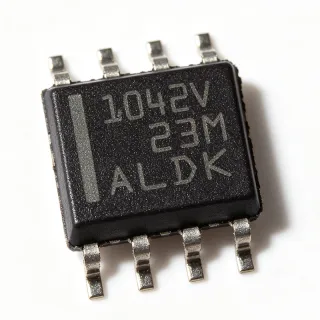
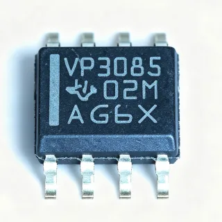
TCAN1051HVDR - 2Mbps CAN FD Fault-Protected Transceiver | TI
부품 번호: TCAN1051HVDR ✓ 활성| 수량 | 단가 | 합계 |
|---|---|---|
| 1 | $1.29 | $1.29 |
| 10 | $1.16 | $11.60 |
| 100 | $0.95 | $95.00 |
| 500 | $0.82 | $410.00 |
| 1,000 | $0.7 | $700.00 |
TCAN1051HVDR 개요
A CAN transceiver is the physical-layer interface IC that converts the TTL-level TXD and RXD signals of a CAN controller into the differential CANH and CANL bus signals defined by ISO 11898-2. Within the signal-chain hierarchy, it sits between the host microcontroller or CAN controller and the twisted-pair bus, providing level translation, dominant/recessive line driving, receiver comparators, and bus-fault protection in a single package.
Key features of the TCAN1051HV include compliance with the ISO 11898-2:2016 and ISO 11898-5:2007 physical layer standards, support for both classic CAN and 2 Mbps CAN FD frames (so-called Turbo CAN), and fault protection on the bus pins that survives fault conditions common in harsh electrical environments. The device is functional-safety-capable, with documentation available from TI to aid functional safety system design, an important benefit for automotive and industrial programs.
Technically, the transceiver integrates a differential driver and receiver optimized for fast signal transitions and controlled symmetry, allowing reliable operation at CAN FD arbitration and data phases with short data bits. The receiver stage includes dominant-timeout behavior, and the protected bus pins tolerate electrical faults such as short circuits to battery voltage or ground, reducing field-failure rates in 12 V and 24 V systems.
Typical applications include automotive body and powertrain ECUs, industrial PLC and fieldbus nodes, building automation controllers, and battery management systems - all environments where bus wiring faults, transient events, and wide temperature ranges are expected.
For design, place a 100 nF decoupling capacitor close to VCC, use a split-termination or 120 ohm bus termination scheme per the ISO 11898-2 standard, and confirm thermal margin if multiple transceivers share a crowded board.
This page adds value beyond the datasheet by combining verified distributor pricing, drop-in alternatives, a parameter comparison table, and practical design notes in one place.
드롭인 대체품: TCAN1051HVDR — 동일 패키지, 핀 호환. PCB 재작업이 필요한 다른 패키지 부품은 제외됩니다.
이 시리즈의 변형
다음과 드롭인 호환되는 동일 시리즈 모델: TCAN1051HVDR (동일 폼 팩터 및 풋프린트) — 차이점: Data Rate, Package, Product Type, Fault Protection, Packaging.
빠른 비교 도구 — 나란히 비교할 대체 부품을 선택하십시오:
TCAN1051HVDRQ1
✅ 드롭인📋 참조 대체품 (카탈로그에 없음)
TCAN1051HVDQ1
✅ 드롭인✓ 재고 있음
$1 / 개
데이터시트 보기 →TCAN1051GVDRQ1
✅ 드롭인✓ 재고 있음
$1.28 / 개
데이터시트 보기 →TCAN1051VDRBTQ1
✅ 드롭인✓ 재고 있음
$1.79 / 개
데이터시트 보기 →TCAN1051VDRQ1
✅ 드롭인✓ 재고 있음
$0.31 / 개
데이터시트 보기 →TCAN1051HGVDRQ1
✅ 드롭인✓ 재고 있음
$1.02 / 개
데이터시트 보기 →TCAN1051HVDR 사양
| Product Type | Fault-protected CAN FD transceiver |
| Protocol Support | Classic CAN and CAN FD (2 Mbps) |
| Supply Voltage Range | 4.5 V to 5.5 V |
| 데이터 속도 | 2 Mbps (CAN FD data phase) |
| Number of Drivers | 1 |
| Number of Receivers | 1 |
| Duplex | Half duplex |
| Standards Compliance | ISO 11898-2:2016, ISO 11898-5:2007 |
| 동작 온도 | -55C to +125C |
| 패키지 | SOIC (D), 8 pins |
| 실장 유형 | Surface Mount |
| Functional Safety | Functional-safety-capable documentation available |
| Fault Protection | Bus fault protected (CANH/CANL) |
| Packaging | Tape and Reel (T/R) |
| RoHS 상태 | Compliant |
TCAN1051HVDR 핀 구성
| 핀 1 | TXD — Transmit data input from CAN controller |
| 핀 2 | GND — Ground reference |
| 핀 3 | VCC — Supply voltage, 4.5 V to 5.5 V |
| 핀 4 | RXD — Receive data output to CAN controller |
| 핀 5 | VIO — I/O level reference supply for TXD/RXD logic |
| 핀 6 | CANL — CAN low bus line (fault protected) |
| 핀 7 | CANH — CAN high bus line (fault protected) |
| 핀 8 | STB — Standby mode control input |
일반적인 애플리케이션
TCAN1051HVDR 적합 용도: 6 애플리케이션s: Automotive ECU CAN Networks, Industrial PLC and Fieldbus Nodes, Battery Management Systems, Building Automation and HVAC Controllers, Medical and Laboratory Equipment, Agricultural and Off-Highway Vehicles.
Automotive ECU CAN Networks
The TCAN1051HVDR fits automotive ECU bus interfaces because it meets ISO 11898-2:2016, supports 2 Mbps CAN FD for modern in-vehicle backbones, and tolerates -55C to +125C ambient conditions found in engine-bay and body-electronics modules. The fault-protected CANH/CANL pins survive wiring-harness faults such as shorts to battery or ground, directly reducing warranty returns. In use, the transceiver connects the MCU CAN controller TXD/RXD pins to the differential bus, with a 120 ohm termination at each network end and VIO allowing 3.3 V logic compatibility. The SOIC-8 footprint keeps BOM area minimal, and for programs requiring AEC-Q100 paper trail, the pin-compatible TCAN1051HVDRQ1 drops onto the same PCB.
추천
Industrial PLC and Fieldbus Nodes
Industrial controllers use CANopen and CAN FD fieldbuses where the TCAN1051HVDR's 2 Mbps data phase shortens cycle times for motion and I/O updates versus classic 500 kbps CAN. Its ISO 11898-2:2016 compliance guarantees interoperability with mixed-vendor industrial networks, while the wide 4.5 V to 5.5 V supply range tolerates noisy 24 V-backplane-derived rails. Bus-pin fault protection is valuable in factory wiring where cable damage and miswiring occur. Implementation is straightforward: couple the transceiver between the PLC MCU and the fieldbus stub, add split termination for EMC, and use the -55C to +125C rating for cabinet-free installations. VIO operation with 3.3 V MCUs eliminates level-shifting logic.
추천
Battery Management Systems
In BMS daisy chains, the TCAN1051HVDR links battery-pack controllers to vehicle or inverter CAN networks. The HV variant's wide -55C to +125C range suits packs mounted near heat sources, and its fault-protected bus pins tolerate harness faults in high-voltage vehicle environments. TI's TCAN1051 family pairs naturally with the BQ76952 battery-monitor family in typical reference designs. In this topology, the pack controller's CAN FD peripheral drives TXD/RXD while VIO matches 3.3 V logic domains; 2 Mbps CAN FD data phases speed cell-voltage and SOC report transmission compared to classic CAN. For automotive packs, swap in the pin-compatible TCAN1051HVDRQ1 for qualification, and add a digital isolator between controller and transceiver when high-voltage isolation is required.
추천
Building Automation and HVAC Controllers
Building automation systems frequently run CAN-based control networks (e.g., elevator controllers, air-handling units) where the TCAN1051HVDR's ISO 11898-2:2016 compliance and half-duplex 1-driver/1-receiver configuration match standard node requirements. The 2 Mbps CAN FD capability allows future firmware upgrades to higher-throughput messaging without hardware change, and the protected bus pins handle field miswiring during installation. Operating from a 5 V rail with VIO supporting 3.3 V controller logic simplifies the power tree in wall-mounted thermostats and zone controllers. The SOIC-8 package fits dense controller boards, and the -55C to +125C rating covers rooftop equipment extremes without derating concerns at typical 85C cabinet ambients.
추천
Medical and Laboratory Equipment
Modular medical instruments use internal CAN networks to connect sensor, actuator, and display modules to a main controller, where the TCAN1051HVDR contributes low-EMI differential signaling per ISO 11898-2:2016 and robust fault protection against backplane wiring events. The device's functional-safety-capable documentation from TI supports IEC 60601-associated system design efforts by providing quality and safety analysis material. Its 2 Mbps CAN FD support reduces latency for real-time control loops such as pump and valve actuation. Design practice: run the transceiver on a clean 5 V rail, decouple with 100 nF close to VCC, and isolate the bus with a digital isolator when the module floats at patient-connected potentials. The SOIC-8 package suits compact rack modules.
추천
Agricultural and Off-Highway Vehicles
Tractors, harvesters, and construction machines run ISOBUS (ISO 11783) CAN networks in severe environments: wide temperature swings, vibration, salt, and frequent harness faults. The TCAN1051HVDR addresses these with -55C to +125C operation, ISO 11898-2:2016 compliant signaling, and bus-pin fault protection that survives shorts to battery or ground - common failure modes when implements are coupled. Classic CAN compatibility covers legacy ISOBUS traffic while 2 Mbps CAN FD readiness supports next-generation implement networks. The VIO pin eases interfacing with 3.3 V engine-control MCUs. Recommended practice includes common-mode choke and TVS diodes at the connector, plus the pin-compatible TCAN1051HVDRQ1 variant when OEM qualification demands AEC-Q100 documentation.
추천
추천 제품 요약
엔지니어링 참조 데이터: TCAN1051HVDR — 비교, 설계 지침 및 규정 준수 정보.
선택 가이드
대체품과의 비교
| 파라미터 | 이 제품 | TCAN1051HVDRQ1 | TCAN1051GVDRQ1 | TCAN1051VDRBTQ1 | TCAN1051HGVDRQ1 |
|---|---|---|---|---|---|
| Package | SOIC-8 (D) | SOIC-8 (D) - same | SOIC-8 (D) - same | SOIC-8 (D) - same | SOIC-8 (D) - same |
| Brand | Texas Instruments | Texas Instruments | Texas Instruments | Texas Instruments | Texas Instruments |
| Supply Voltage | 4.5 V to 5.5 V | 4.5 V to 5.5 V | 4.5 V to 5.5 V | 4.5 V to 5.5 V | 4.5 V to 5.5 V |
| AEC-Q100 Qualified | No (standard grade) | Yes (Q1 suffix) | Yes (Q1 suffix) | Yes (Q1 suffix) | Yes (Q1 suffix) |
| Bus Fault Protection | Yes (HV variant) | Yes (HV variant) | Yes (G variant) | Yes (V variant) | Yes (HG - higher fault voltage) |
주요 차별점
- HV variant wide temperature and fault rating without Q1 pricing premium (vs TCAN1051HVDRQ1)
- Same-pinout upgrade path to higher bus-fault tolerance (vs TCAN1051HGVDRQ1)
- Functional-safety-capable documentation (vs TCAN1051HVDRQ1)
설계 노트
Place a 100 nF ceramic decoupling capacitor within 2-3 mm of the VCC pin (pin 3) with a solid ground return to pin 2. The CANH/CANL traces should be a tightly coupled differential pair routed away from switching regulator nodes; keep the stub from transceiver to bus connector short. VIO (pin 5) should be decoupled with its own 100 nF capacitor when it is tied to a 3.3 V rail. Follow TI's TCAN1051 evaluation-module layout as a reference pattern.
Do not leave the STB pin (pin 8) floating - tie it to the correct level for always-active operation or drive it from the MCU for standby control, otherwise the transceiver may sit in standby and the bus will appear dead. Ensure both ends of the bus are terminated with 120 ohms (or a split-termination network) per ISO 11898-2; unterminated stubs cause reflections and CAN FD bit errors at the 2 Mbps data phase. Confirm VIO matches the controller logic supply before powering up.
Estimated: at a 5.5 V maximum supply, the transceiver's dominant-mode drive current (tens of milliamps typical for CAN transceivers) implies power dissipation well under 0.5 W in the SOIC-8 package, comfortably within its thermal capability at 125C ambient with standard 2-layer copper. Verify against the datasheet supply-current curves for your actual bus loading and dominant-duty-cycle; avoid running at the 5.5 V maximum continuously in sealed enclosures with limited airflow.
규정 준수 정보
RoHS compliance per standard TI interface-IC qualification; the TCAN1051HVDRQ1 variant carries AEC-Q100 automotive qualification. REACH, halogen-free, and conflict-minerals status should be confirmed on the TI product page quality folder.