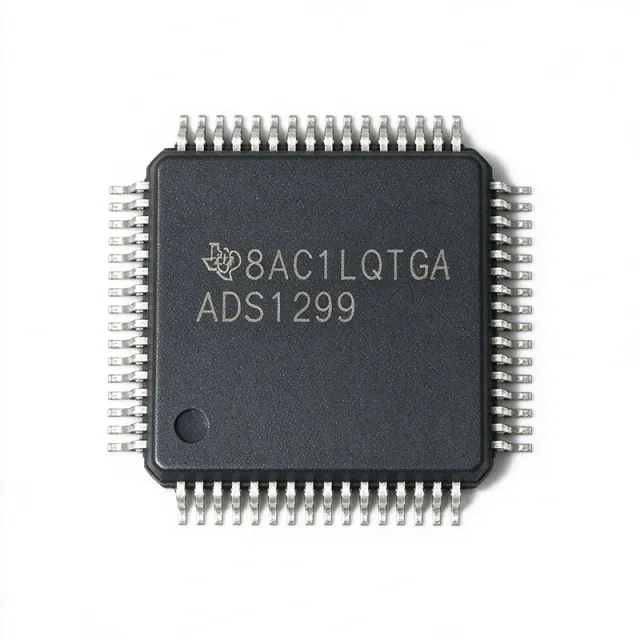
ADS1299-6PAG - 6-Ch 24-Bit Low-Noise AFE for EEG/Biopotential | TI
MPN: ADS1299-6PAG ✓ Active| Qty | Unit Price | Extended |
|---|---|---|
| 1 | $33.71 | $33.71 |
| 10 | $31.45 | $314.50 |
| 100 | $28.2 | $2,820.00 |
| 500 | $25.1 | $12,550.00 |
| 1,000 | $22.05 | $22,050.00 |
ADS1299-6PAG Overview
A biopotential analog front end (AFE) is a specialized mixed-signal IC that combines low-noise amplification, multi-pole analog filtering, and high-resolution digitization in a single chip, replacing the traditional discrete chain of instrumentation amp + anti-alias filter + ADC. In the broader system hierarchy, an AFE sits at the signal-chain boundary between the analog sensor domain (electrodes, transducers) and the digital processing domain (MCU/DSP/FPGA). The ADS1299-6 specifically addresses extracranial electroencephalogram (EEG), electrocardiogram (ECG), electromyography (EMG), and brain-computer interface (BCI) applications where the combination of sub-uV noise floor, high common-mode rejection, and simultaneous multi-channel sampling is mandatory.
Key features include 1 uVPP input-referred noise at 70 Hz BW, -110 dB CMRR, programmable gain from 1 to 24 in 7 discrete steps, internal 4.033 V reference, internal oscillator, and daisy-chain capability for high channel-count systems. The device supports SPI-compatible serial communication and consumes approximately 33 mW total, with a flexible right-leg drive (RLD) loop per channel for bias electrode driving. The 64-TQFP package provides ample thermal headroom for portable multi-channel designs.
Architecturally, the ADS1299-6 uses a third-order delta-sigma modulator per channel followed by a digital SINC filter chain, achieving simultaneous sampling by sharing a common DRDY signal. The integrated PGA front-end, matched with the modulator's low-noise input stage, allows the device to resolve signals in the sub-uV range critical for EEG micro-features. Internal calibration and self-test routines plus a dedicated bias amplifier streamline biopotential front-end designs.
Typical applications include clinical-grade EEG headsets, research-grade BCI platforms, polysomnography, ECG/EMG patient monitors, evoked-potential instrumentation, and bioimpedance research front-ends. The simultaneous-sampling architecture preserves inter-channel phase relationships required for source localization and coherence analysis in neuroscience research.
When designing with this part, careful PCB layout of the analog ground plane, dedicated low-noise LDO rails for AVDD/AVSS, and proper patient-electrode bias return are essential to realize the 1 uVPP noise specification. Use the daisy-chain interface when extending beyond 6 channels by stacking additional ADS1299-x devices on the same SPI bus.
This page synthesizes distributor stock, drop-in cross-reference options, and practical biopotential design considerations not found in the manufacturer datasheet alone, accelerating your EEG/BCI/biomedical product development.
Drop-in alternatives for ADS1299-6PAG — same package, pin-to-pin compatible. Different-package parts requiring PCB rework are excluded.
Variants in this series
Same-series models that are drop-in compatible with ADS1299-6PAG (same form factor and footprint) — differing in Architecture, Input-Referred Noise, Internal Reference, Number of Channels, Package.
Quick Comparison Tool — Select alternative parts for side-by-side comparison:
ADS1299IPAGR
✓ In Stock
$22.1 / Unit
View Datasheet →ADS1299-4PAG
📋 Reference alternative (not in catalog)
ADS1299-6PAGR
📋 Reference alternative (not in catalog)
ADS1299-6IPAG
📋 Reference alternative (not in catalog)
ADS1299-6PAG Maximum Ratings & Electrical Characteristics
| Number of Channels | 6 |
| Resolution | 24-bit |
| Architecture | Delta-Sigma (ΔΣ) |
| Input-Referred Noise | 1 uVPP (70 Hz BW) |
| CMRR | -110 dB |
| Data Rate | 250 SPS to 16 kSPS |
| Programmable Gain | 1, 2, 4, 6, 8, 12, 24 |
| Sampling | Simultaneous-sampling across all channels |
| Input Bias Current | 300 pA |
| Power Consumption | 33 mW |
| Internal Reference | 4.033 V |
| Onboard Oscillator | Yes |
| Digital Interface | SPI-compatible |
| Daisy-Chain Support | Yes (for high channel-count systems) |
| Package | TQFP-64 (PAG) 10x10 mm |
| Mounting Type | Surface Mount |
| Operating Temperature | -40C to +85C |
| Family | ADS1299-x (4-, 6-, 8-channel variants) |
ADS1299-6PAG Pin Configuration
| Pin 1 | IN1P — Channel 1 positive analog input |
| Pin 2 | IN1N — Channel 1 negative analog input |
| Pin 3 | IN2P — Channel 2 positive analog input |
| Pin 4 | IN2N — Channel 2 negative analog input |
| Pin 5 | IN3P — Channel 3 positive analog input |
| Pin 6 | IN3N — Channel 3 negative analog input |
| Pin 7 | IN4P — Channel 4 positive analog input |
| Pin 8 | IN4N — Channel 4 negative analog input |
| Pin 9 | IN5P — Channel 5 positive analog input |
| Pin 10 | IN5N — Channel 5 negative analog input |
| Pin 11 | IN6P — Channel 6 positive analog input |
| Pin 12 | IN6N — Channel 6 negative analog input |
| Pin 13 | RLD — Right-leg drive amplifier output |
| Pin 14 | BIAS — Bias amplifier output |
| Pin 15 | AVSS — Analog negative supply / ground |
| Pin 16 | AVDD — Analog positive supply (typically 5 V) |
| Pin 17 | AVSS1 — Analog ground reference 1 |
| Pin 18 | AVDD1 — Analog supply reference 1 |
| Pin 19 | VCAP1 — Decoupling capacitor pin 1 |
| Pin 20 | VCAP2 — Decoupling capacitor pin 2 |
| Pin 21 | VCAP3 — Decoupling capacitor pin 3 |
| Pin 22 | VCAP4 — Decoupling capacitor pin 4 |
| Pin 23 | AVSS2 — Analog ground reference 2 |
| Pin 24 | AVDD2 — Analog supply reference 2 |
| Pin 25 | GPIO1 — General-purpose I/O 1 |
| Pin 26 | GPIO2 — General-purpose I/O 2 |
| Pin 27 | GPIO3 — General-purpose I/O 3 |
| Pin 28 | GPIO4 — General-purpose I/O 4 |
| Pin 29 | DRDY — Data ready output (active low) |
| Pin 30 | CLKSEL — Clock select (internal/external) |
| Pin 31 | SCLK — SPI serial clock input |
| Pin 32 | DIN — SPI data input |
| Pin 33 | DOUT — SPI data output |
| Pin 34 | CS — SPI chip select (active low) |
| Pin 35 | START — Conversion start input |
| Pin 36 | PWDN — Power-down input (active low) |
| Pin 37 | RESET — Reset input (active low) |
| Pin 38 | DAISY_IN — Daisy-chain data input |
| Pin 39 | TEST — Test mode pin (tie low for normal operation) |
| Pin 40 | DVDD — Digital positive supply (1.8 V to 3.3 V) |
| Pin 41 | DGND — Digital ground |
| Pin 42 | AVSS3 — Analog ground reference 3 |
| Pin 43 | AVDD3 — Analog supply reference 3 |
| Pin 44 | VCAP5 — Decoupling capacitor pin 5 |
| Pin 45 | VCAP6 — Decoupling capacitor pin 6 |
| Pin 46 | VCAP7 — Decoupling capacitor pin 7 |
| Pin 47 | VCAP8 — Decoupling capacitor pin 8 |
| Pin 48 | AVSS4 — Analog ground reference 4 |
| Pin 49 | AVDD4 — Analog supply reference 4 |
| Pin 50 | NC — Not connected (per datasheet) |
| Pin 51 | NC — Not connected (per datasheet) |
| Pin 52 | NC — Not connected (per datasheet) |
| Pin 53 | NC — Not connected (per datasheet) |
| Pin 54 | NC — Not connected (per datasheet) |
| Pin 55 | NC — Not connected (per datasheet) |
| Pin 56 | NC — Not connected (per datasheet) |
| Pin 57 | NC — Not connected (per datasheet) |
| Pin 58 | NC — Not connected (per datasheet) |
| Pin 59 | NC — Not connected (per datasheet) |
| Pin 60 | NC — Not connected (per datasheet) |
| Pin 61 | NC — Not connected (per datasheet) |
| Pin 62 | NC — Not connected (per datasheet) |
| Pin 63 | NC — Not connected (per datasheet) |
| Pin 64 | NC — Not connected (per datasheet) |
Typical Applications
ADS1299-6PAG is suitable for 7 applications: Clinical-Grade EEG Headset, Brain-Computer Interface (BCI) Platform, Polysomnography (PSG) Sleep Monitor, Portable ECG Patient Monitor, Evoked-Potential (EP) Instrumentation, Bioimpedance and Galvanic Skin Response Research, Neuroscience Research Multi-Channel Array.
Clinical-Grade EEG Headset
The ADS1299-6PAG is the de facto industry-standard AFE for clinical EEG headsets due to its 1 uVPP input-referred noise and -110 dB CMRR, both of which are mandatory for resolving sub-Hz delta waves and high-frequency gamma activity. Its 6-channel simultaneous-sampling architecture preserves inter-hemispheric phase relationships critical for evoked-potential (ERP) and coherence analysis. Powered by a low-noise LDO such as the TPS7A4701, the device delivers <1 uVPP noise floor even with 24x PGA gain. The integrated right-leg drive (RLD) amplifier loop reduces common-mode interference from the mains supply, eliminating the need for bulky discrete instrumentation amplifiers in wearable designs.
Recommended
Brain-Computer Interface (BCI) Platform
BCI research platforms demand sub-microvolt noise and multi-channel simultaneous sampling to decode motor imagery and P300 signals. The ADS1299-6PAG delivers both, with 6 channels sufficient for motor cortex experiments and the daisy-chain interface enabling expansion to 12, 16, or more channels with additional ADS1299-x devices on the same SPI bus. Its integrated PGA eliminates external instrumentation amplifiers, reducing BOM and board area for wearable BCI headsets. The 250 SPS to 16 kSPS data rate covers both slow cortical potentials and high-gamma oscillations.
Recommended
Polysomnography (PSG) Sleep Monitor
Polysomnography combines EEG, EOG, EMG, and ECG channels to characterize sleep stages. The ADS1299-6PAG handles multiple modalities on a single chip thanks to its flexible input architecture and 1 uVPP noise that suits both EEG and EMG signal ranges. Six channels are sufficient for a 4-EEG + 2-EOG minimal PSG configuration, with daisy-chain expansion for full 10-20 EEG arrays. The internal 4.033 V reference and onboard oscillator minimize external components, enabling compact bedside or wearable PSG designs with simplified calibration routines.
Recommended
Portable ECG Patient Monitor
Portable ECG monitors require high CMRR (>100 dB) to reject mains interference and sub-uV noise floor to resolve mV-range cardiac signals with diagnostic accuracy. The ADS1299-6PAG satisfies both with its -110 dB CMRR and 1 uVPP noise, while its integrated RLD amplifier loop drives the bias electrode to actively suppress 50/60 Hz interference. Six channels enable lead-II, lead-V, and respiration measurements plus spare channels for backup. Total power consumption of 33 mW across all channels supports battery-powered Holter and telemetry designs.
Recommended
Evoked-Potential (EP) Instrumentation
Auditory, visual, and somatosensory evoked-potential systems require averaging across many stimulus trials to extract sub-uV brain responses from noise. The ADS1299-6PAG's 1 uVPP noise and 24-bit resolution minimize the number of averages required, accelerating clinical workflows. Simultaneous multi-channel sampling preserves the timing relationships between cortical regions, which is essential for source localization of EP generators. The SPI interface allows direct DMA streaming into MCUs or FPGAs for real-time averaging.
Recommended
Bioimpedance and Galvanic Skin Response Research
Research platforms combining bioimpedance (BI), galvanic skin response (GSR), and biopotential measurements benefit from the ADS1299-6PAG's multi-channel flexibility. The PGA inputs accept the small AC excitation currents used in bioimpedance measurements, while remaining channels record simultaneous EEG or ECG. The wide programmable gain range (1x to 24x) accommodates both high-amplitude GSR responses and low-amplitude EEG. Six channels provide sufficient headroom for multimodal research prototypes without requiring multiple AFEs.
Recommended
Neuroscience Research Multi-Channel Array
Large-channel neuroscience arrays (>8 channels) can be built by daisy-chaining multiple ADS1299-6PAG devices on a single SPI bus, exploiting TI's documented daisy-chain protocol. Each device adds 6 channels while preserving the simultaneous-sampling property across the entire array, essential for source-localization algorithms. The 33 mW per device power budget scales linearly, allowing 128-channel systems at approximately 700 mW total. Onboard oscillator and internal reference simplify multi-device clock synchronization.
Recommended
Recommended Products Summary
Engineering reference data for ADS1299-6PAG — comparison, design guidance, and compliance information.
Selection Guide
Comparison with Alternatives
| Parameter | This Product | ADS1299IPAG | ADS1299-4PAG | ADS1299-6PAGR | ADS1299-6IPAG |
|---|---|---|---|---|---|
| Brand | Texas Instruments | Texas Instruments | Texas Instruments | Texas Instruments | Texas Instruments |
| Package | TQFP-64 (PAG) 10x10 mm | TQFP-64 (PAG) - same | TQFP-64 (PAG) - same | TQFP-64 (PAG) - same | TQFP-64 (PAG) - same |
| Number of Channels | 6 | 8 | 4 | 6 | 6 |
| Resolution | 24-bit | 24-bit | 24-bit | 24-bit | 24-bit |
| Input-Referred Noise | 1 uVPP (70 Hz BW) | 1 uVPP (70 Hz BW) | 1 uVPP (70 Hz BW) | 1 uVPP (70 Hz BW) | 1 uVPP (70 Hz BW) |
| CMRR | -110 dB | -110 dB | -110 dB | -110 dB | -110 dB |
| Data Rate | 250 SPS to 16 kSPS | 250 SPS to 16 kSPS | 250 SPS to 16 kSPS | 250 SPS to 16 kSPS | 250 SPS to 16 kSPS |
| Power Consumption | 33 mW | 33 mW | 33 mW | 33 mW | 33 mW |
| Programmable Gain | 1, 2, 4, 6, 8, 12, 24 | 1, 2, 4, 6, 8, 12, 24 | 1, 2, 4, 6, 8, 12, 24 | 1, 2, 4, 6, 8, 12, 24 | 1, 2, 4, 6, 8, 12, 24 |
| Operating Temperature | -40C to +85C | -40C to +85C | -40C to +85C | -40C to +85C | -40C to +85C |
Key Differentiators
- Industry-leading 1 uVPP input-referred noise (vs ADS130E08)
- Integrated biopotential-specific features (vs ADS1274IPAPT)
- 6-channel option in the same TQFP-64 footprint (vs ADS1299IPAG)
Design Notes
Power the ADS1299-6PAG from a low-noise LDO such as the TPS7A4701 for the AVDD rail (5 V) and a separate low-noise regulator for DVDD (1.8 V to 3.3 V). Place 1 uF X7R ceramic decoupling capacitors on every AVDD and AVSS pin pair plus 0.1 uF capacitors close to the package for high-frequency noise suppression. The 1 uVPP noise floor is unachievable with noisy switching regulators on the analog rail; use LC filters between switching converters and the AFE supply pins. Estimated: with proper LDO supply, total noise contribution from supply is <0.1 uVrms.
Implement a continuous analog ground plane beneath the ADS1299-6PAG, segregated from the digital ground plane, joined only at a single point near the AFE's AVSS pin. Route the analog input traces INxP/INxN as differential pairs with 50-ohm characteristic impedance and matched lengths (within 0.5 mm) to preserve -110 dB CMRR. Place input common-mode bias resistors (typically 100 kohm to AVSS/AVDD midpoint) close to the IC pins to set the DC operating point and prevent input saturation.
Do not connect unused analog inputs (NC pins 50-64) to any signal source; per TI datasheet they must remain floating to prevent internal bias disturbance. Tie CLKSEL high for internal oscillator mode (default) and low only when an external clock is supplied. Always assert RESET after power stabilization for at least 2 clock cycles, then wait 1 ms before issuing SDATAC and configuration commands. Do not exceed 5.5 V on AVDD or 3.6 V on DVDD to avoid latch-up. Estimated: typical post-reset settling time is 1 ms; consult TI datasheet timing diagram for exact values.
Route SPI traces (SCLK, DIN, DOUT, CS, DRDY) as short as possible (under 50 mm) and surround with digital ground. Place a 100 ohm series resistor near the DOUT pin to dampen ringing on long SPI traces. Keep the START, PWDN, and RESET traces away from analog input traces to prevent capacitive coupling of digital transients into the sensitive analog front-end. Use guard rings around the analog input traces tied to AVSS to further reduce stray pickup.
For simultaneous-sampling integrity, ensure the START signal is distributed with matched trace lengths to all daisy-chained ADS1299-x devices; any timing skew between devices will degrade inter-channel phase coherence. Use the internal oscillator for single-device designs, but switch to an external low-jitter clock when daisy-chaining multiple devices to maintain synchronization. Verify inter-channel crosstalk at full gain by shorting inputs of inactive channels and measuring active-channel noise floor degradation; <0.5 uVrms increase indicates clean PCB design.
Compliance Information
RoHS and REACH compliant per TI product page. Not AEC-Q100 qualified - the ADS1299-6PAG is intended for medical research and clinical applications, not automotive use. Refer to TI product page for medical device compliance documentation including IEC 60601-1 support resources.







