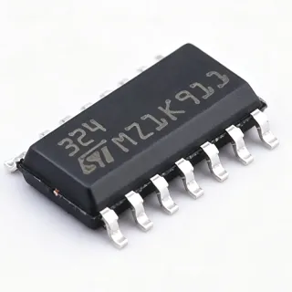
ADUM3196ARWZ-RL7 - Isolated Error Amplifier | Analog Devices
MPN: ADUM3196ARWZ-RL7 ✓ Active| Qty | Unit Price | Extended |
|---|---|---|
| 1 | $3.42 | $3.42 |
| 10 | $3.08 | $30.80 |
| 100 | $2.74 | $274.00 |
| 500 | $2.47 | $1,235.00 |
| 1,000 | $2.19 | $2,190.00 |
ADUM3196ARWZ-RL7 Overview
An isolated error amplifier is a specialized amplifier that provides electrical isolation between its input and output while maintaining accurate signal transfer. It is commonly used in isolated power supplies to sense output voltage or current and feed back a control signal across the isolation barrier. The ADUM3196ARWZ-RL7 belongs to the category of isolation amplifiers, which are part of the broader family of analog signal conditioning ICs. These components are essential in applications requiring safety isolation, noise immunity, and ground loop elimination.
Key features of the ADUM3196ARWZ-RL7 include a wide input common-mode voltage range of -0.3 V to 20 V, a fixed gain of 1 V/V (adjustable with external resistors), and a high common-mode transient immunity of 25 kV/µs. The device is available in a 16-lead SOIC (RW-16) package, which is compact and suitable for space-constrained designs. It also features an internal reference of 1.2 V and a shutdown pin for power saving. The operating temperature range is -40°C to +125°C, making it suitable for industrial and automotive environments.
Technically, the ADUM3196ARWZ-RL7 uses a proprietary iCoupler transformer-based isolation technology, which offers superior performance compared to optocouplers, including higher speed, better temperature stability, and longer lifespan. The device includes an internal voltage reference and an error amplifier with a transconductance output stage, allowing direct connection to a shunt regulator or a PWM controller. The gain can be set externally using two resistors, providing design flexibility. The output is single-ended, simplifying interface with downstream control circuits.
Typical applications include isolated voltage sensing in AC-DC power supplies, isolated current sensing in motor drives, and feedback control in solar inverters. The device is also used in battery management systems and industrial automation where galvanic isolation is required. Its high common-mode transient immunity ensures reliable operation in noisy environments.
When designing with the ADUM3196ARWZ-RL7, it is important to provide adequate decoupling on both supply pins and to ensure that the isolation barrier is not stressed beyond its rated voltage. The gain-setting resistors should be precision types to maintain accuracy. The device is RoHS compliant and lead-free, meeting environmental standards.
Drop-in alternatives for ADUM3196ARWZ-RL7 — same package, pin-to-pin compatible. Different-package parts requiring PCB rework are excluded.
Variants in this series
Same-series models that are drop-in compatible with ADUM3196ARWZ-RL7 (same form factor and footprint) — differing in Bandwidth, Gain, Package.
Quick Comparison Tool — Select alternative parts for side-by-side comparison:
ADUM3196ARWZ
✅ Drop-In ⚠️ Specs Unverified✓ In Stock
$2.19 / Unit
View Datasheet →ADUM3196ARWZ-RL
✅ Drop-In ⚠️ Specs Unverified📋 Reference alternative (not in catalog)
ADUM3196ARWZ-RL7 Maximum Ratings & Electrical Characteristics
| Isolation Type | iCoupler |
| Number of Channels | 1 |
| Type | Isolated Error Amplifier |
| Gain | 1 V/V (adjustable) |
| Bandwidth | 200 kHz |
| Supply Voltage - Primary | 3.0 V to 20 V |
| Supply Voltage - Secondary | 3.0 V to 20 V |
| Quiescent Current | 1.2 mA (typical) |
| Input Common-Mode Voltage Range | -0.3 V to 20 V |
| Common-Mode Transient Immunity | 25 kV/µs |
| Internal Reference | 1.2 V |
| Operating Temperature Range | -40°C to +125°C |
| Package | 16-Lead SOIC (RW-16) |
| Mounting Type | Surface Mount |
| RoHS | Compliant |
| Lead-Free | Yes |
ADUM3196ARWZ-RL7 Pin Configuration
| Pin 1 | VDD1 — Primary side supply voltage |
| Pin 2 | GND1 — Primary side ground |
| Pin 3 | IN+ — Non-inverting input |
| Pin 4 | IN- — Inverting input |
| Pin 5 | GND1 — Primary side ground |
| Pin 6 | NC — No connect |
| Pin 7 | NC — No connect |
| Pin 8 | NC — No connect |
| Pin 9 | NC — No connect |
| Pin 10 | NC — No connect |
| Pin 11 | NC — No connect |
| Pin 12 | NC — No connect |
| Pin 13 | OUT — Error amplifier output |
| Pin 14 | GND2 — Secondary side ground |
| Pin 15 | VDD2 — Secondary side supply voltage |
| Pin 16 | NC — No connect |
Typical Applications
ADUM3196ARWZ-RL7 is suitable for 6 applications: Isolated Power Supply Feedback, Shunt Regulator Control, Inverter and UPS Systems, Motor Drives, Battery Management Systems, Solar Inverters.
Isolated Power Supply Feedback
The ADUM3196ARWZ-RL7 is used in isolated AC-DC and DC-DC power supplies to provide feedback from the secondary side to the primary controller. Its high common-mode transient immunity (25 kV/µs) ensures stable operation in noisy switching environments. The adjustable gain allows precise setting of the output voltage regulation point. With a bandwidth of 200 kHz, it supports fast transient response, improving overall converter performance. The device's wide supply voltage range (3.0 V to 20 V) makes it compatible with various bias supplies. In this application, the error amplifier senses the output voltage and generates an error signal that is transmitted across the isolation barrier to adjust the PWM duty cycle. This eliminates the need for optocouplers, enhancing reliability and longevity.
Recommended
Shunt Regulator Control
In shunt regulator circuits, the ADUM3196ARWZ-RL7 provides isolated error amplification to maintain a stable output voltage. Its internal 1.2 V reference and adjustable gain allow precise regulation. The device's high bandwidth (200 kHz) ensures fast correction of output variations. The wide input common-mode voltage range (-0.3 V to 20 V) accommodates various shunt configurations. The isolation provided by iCoupler technology protects the control circuitry from high voltages on the shunt side. This application is common in precision voltage references and battery chargers. The ADUM3196's low quiescent current (1.2 mA) minimizes power loss, making it suitable for energy-efficient designs.
Recommended
Inverter and UPS Systems
The ADUM3196ARWZ-RL7 is used in inverters and uninterruptible power supplies (UPS) for isolated voltage and current sensing. Its high common-mode transient immunity (25 kV/µs) ensures reliable operation in high-voltage switching environments. The device's wide supply voltage range (3.0 V to 20 V) allows it to be powered from various auxiliary supplies. The adjustable gain enables precise scaling of sensed signals to match ADC input ranges. The isolation barrier protects low-voltage control electronics from high-voltage transients. With a bandwidth of 200 kHz, it can capture fast transients, improving system protection. The device's operating temperature range (-40°C to +125°C) makes it suitable for harsh industrial environments.
Recommended
Motor Drives
In motor drive systems, the ADUM3196ARWZ-RL7 provides isolated current sensing for feedback control. Its high common-mode transient immunity (25 kV/µs) ensures accurate measurement in the presence of high dv/dt from PWM switching. The device's wide input common-mode voltage range (-0.3 V to 20 V) accommodates various shunt resistor configurations. The adjustable gain allows optimization of the signal level for the ADC. The isolation provided by iCoupler technology eliminates ground loops and improves noise immunity. With a bandwidth of 200 kHz, it can capture motor current waveforms with high fidelity. The device's small SOIC package is suitable for space-constrained motor drive boards.
Recommended
Battery Management Systems
The ADUM3196ARWZ-RL7 is used in battery management systems (BMS) for isolated voltage monitoring of individual cells or packs. Its high accuracy (±1% gain) ensures precise voltage measurement. The device's wide supply voltage range (3.0 V to 20 V) allows it to be powered from the battery pack itself. The isolation barrier protects the monitoring circuitry from high battery voltages. The adjustable gain enables scaling of the sensed voltage to match the ADC input range. With a bandwidth of 200 kHz, it can capture fast voltage transients during charging and discharging. The device's low quiescent current (1.2 mA) is beneficial for battery-powered applications.
Recommended
Solar Inverters
In solar inverters, the ADUM3196ARWZ-RL7 is used for isolated voltage and current sensing in the DC-DC and DC-AC stages. Its high common-mode transient immunity (25 kV/µs) ensures reliable operation in high-voltage environments. The device's wide supply voltage range (3.0 V to 20 V) allows it to be powered from auxiliary supplies. The adjustable gain enables precise scaling of sensed signals for maximum power point tracking (MPPT) algorithms. The isolation barrier protects control electronics from high DC bus voltages. With a bandwidth of 200 kHz, it can respond quickly to changing solar conditions. The device's operating temperature range (-40°C to +125°C) is suitable for outdoor installations.
Recommended
Recommended Products Summary
Engineering reference data for ADUM3196ARWZ-RL7 — comparison, design guidance, and compliance information.
Selection Guide
Comparison with Alternatives
| Parameter | This Product | ADUM3195WBRQZ-RL7 | ADUM3190ARQZ-RL7 | ADUM4195WBRQZ-RL7 |
|---|---|---|---|---|
| Package | 16-SOIC | 16-QSOP | 16-QSOP | 16-QSOP |
| Brand | Analog Devices | Analog Devices | Analog Devices | Analog Devices |
| Supply Voltage Range | 3.0 V to 20 V | 3.0 V to 20 V | 3.0 V to 5.5 V | 3.0 V to 20 V |
| Bandwidth | 200 kHz | 200 kHz | 100 kHz | 200 kHz |
| Common-Mode Transient Immunity | 25 kV/µs | 25 kV/µs | 25 kV/µs | 25 kV/µs |
| Gain Accuracy | ±1% | ±1% | ±1% | ±1% |
| Automotive Grade | No | Yes | No | Yes |
| Quiescent Current | 1.2 mA | 1.2 mA | 1.2 mA | 1.2 mA |
Key Differentiators
- Higher bandwidth (200 kHz) compared to ADUM3190ARQZ-RL7 (100 kHz) (vs ADUM3190ARQZ-RL7)
- Wider supply voltage range (3.0 V to 20 V) vs ADUM3190ARQZ-RL7 (3.0 V to 5.5 V) (vs ADUM3190ARQZ-RL7)
- SOIC package offers better thermal performance and easier handling than QSOP (vs ADUM3195WBRQZ-RL7)
Design Notes
Ensure both VDD1 and VDD2 are within the specified range of 3.0 V to 20 V. Use 0.1 µF decoupling capacitors close to each supply pin to filter high-frequency noise. For optimal performance, place a 10 µF bulk capacitor on each supply rail if the power source is far from the device.
Maintain proper creepage and clearance distances between the primary and secondary sides of the PCB to meet isolation requirements. The ADUM3196ARWZ-RL7 provides galvanic isolation, but the PCB layout must support the isolation rating. Use a slot or barrier under the device to increase creepage distance if needed.
Do not exceed the absolute maximum ratings for supply voltage or input voltage. The input common-mode voltage range is -0.3 V to 20 V; exceeding this can damage the device. Also, ensure the gain-setting resistors are precision types (1% or better) to maintain gain accuracy. Avoid running traces near high-voltage switching nodes to prevent noise coupling.
Compliance Information
RoHS compliant and lead-free per Analog Devices datasheet. AEC-Q100 not applicable for this commercial grade part.