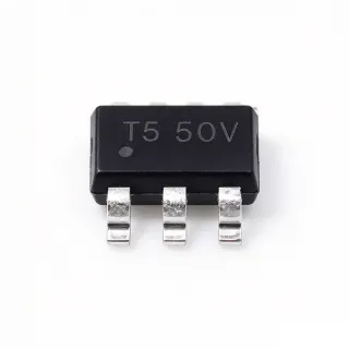
AP62200TWU-7 - 18V/2A Sync Buck Converter, TSOT-23-6 | Diodes Inc
MPN: AP62200TWU-7 ✓ Active| Qty | Unit Price | Extended |
|---|---|---|
| 1 | $0.55 | $0.55 |
| 10 | $0.49 | $4.90 |
| 100 | $0.36 | $36.00 |
| 500 | $0.28 | $140.00 |
| 1,000 | $0.22 | $220.00 |
| 3,000 | $0.18 | $540.00 |
AP62200TWU-7 Overview
A buck converter (step-down switching regulator) is a type of DC-DC converter that uses an internal high-side switch, an external inductor, and synchronous rectification to produce an output voltage lower than its input. It belongs to the switching regulator family within the power management IC hierarchy: buck converter -> switching regulator -> DC-DC converter -> power management IC -> semiconductor. Synchronous buck converters replace the external Schottky diode with an internal low-side MOSFET, dramatically improving efficiency at light loads and shrinking the solution footprint.
Key features include 4.2V to 18V wide input range, 2A continuous output current, 0.8V to 7V adjustable output via external resistor divider, 750kHz switching frequency with PFM pulse-skipping at light loads, internal 90mΩ/65mΩ power MOSFETs, and built-in protection including over-current protection (OCP), over-temperature protection (OTP), and under-voltage lockout (UVLO). The TSOT-23-6 package enables designs as small as a few external passive components.
The AP62200TWU-7 uses constant-on-time (COT) control architecture, providing fast transient response and simple loop compensation. Compared to traditional voltage-mode or current-mode buck converters, COT architecture requires no external compensation network, reducing BOM cost and PCB area. The integrated synchronous MOSFETs eliminate the need for an external Schottky diode, further simplifying the design and improving efficiency to peak values typically above 90% at moderate loads.
Typical applications include distributed 5V/3.3V/1.8V/1.2V rails in set-top boxes, networking equipment, surveillance cameras, IoT gateways, LCD displays, and consumer electronics. The wide 4.2V to 18V input range makes the AP62200TWU-7 suitable for both 5V USB-powered systems and 12V industrial bus systems. When designing with this device, ensure the input capacitor (typically 22µF ceramic) is placed close to the IC pins and the feedback resistor divider uses 1% tolerance resistors for accurate output voltage regulation.
Drop-in alternatives for AP62200TWU-7 — same package, pin-to-pin compatible. Different-package parts requiring PCB rework are excluded.
Quick Comparison Tool — Select alternative parts for side-by-side comparison:
AP62200WU-7
✅ Drop-In📋 Reference alternative (not in catalog)
AP62200TWU-7
✅ Drop-In ⚠️ Specs Unverified✓ In Stock
$0.18 / Unit
View Datasheet →AP62201TWU-7
✅ Drop-In📋 Reference alternative (not in catalog)
AP62300TWU-7
✅ Drop-In📋 Reference alternative (not in catalog)
MP2155GQ-Z
✅ Drop-In📋 Reference alternative (not in catalog)
TPS62177DQCR
✅ Drop-In📋 Reference alternative (not in catalog)
AP62200TWU-7 Maximum Ratings & Electrical Characteristics
| Topology | Synchronous Buck (Step-Down) |
| Input Voltage Range | 4.2 V to 18 V |
| Output Voltage Range | 0.8 V to 7 V (adjustable) |
| Continuous Output Current | 2 A |
| Switching Frequency | 750 kHz |
| Light-Load Operation | PFM pulse-skipping |
| High-Side MOSFET RDS(on) | 90 mΩ |
| Low-Side MOSFET RDS(on) | 65 mΩ |
| Control Architecture | Constant On-Time (COT) |
| Operating Temperature Range | -40 C to +125 C |
| Package | TSOT-23-6 (TSOT26) |
| Mounting Type | Surface Mount |
| MSL Level | 1 (unlimited) |
| Protection Features | OCP, OTP, UVLO |
| RoHS Status | Compliant |
AP62200TWU-7 Pin Configuration
| Pin 1 | BST — Bootstrap capacitor connection for high-side gate driver |
| Pin 2 | GND — Ground return |
| Pin 3 | FB — Feedback voltage input from external resistor divider |
| Pin 4 | EN — Enable input (active-high) |
| Pin 5 | IN — Input supply voltage (4.2V to 18V) |
| Pin 6 | SW — Switch node - connect to external inductor |
Typical Applications
AP62200TWU-7 is suitable for 6 applications: Set-Top Box Distributed Power Rails, Surveillance Camera Power Management, IoT Gateway and Edge Device Power, Networking Equipment Auxiliary Rails, Industrial 12V Bus Point-of-Load, LCD Display Bias and Backlight Power.
Set-Top Box Distributed Power Rails
The AP62200TWU-7 is well suited for set-top box distributed 5V/3.3V/1.8V/1.2V point-of-load rails. Its 4.2V-18V wide input accepts the 12V system bus directly without pre-regulation, and the 2A output current capability covers downstream ASIC and tuner IC requirements. With 750kHz switching and integrated 90mΩ/65mΩ MOSFETs, efficiency peaks above 90% at moderate loads, keeping the TSOT-23-6 package within thermal limits. The PFM light-load mode extends standby efficiency, an important metric for always-on consumer set-top boxes.
Recommended
Surveillance Camera Power Management
Surveillance camera designs benefit from the AP62200TWU-7's small TSOT-23-6 footprint and wide 4.2V-18V input range. The device can be fed from 12V adapters or Power-over-Ethernet (PoE) derived 12V rails, producing 3.3V or 5V for image sensor, ISP, and SoC subsystems. The 750kHz switching frequency is well above the AM radio band, simplifying EMI compliance for camera enclosures. COT architecture provides fast transient response to sudden IR-LED illumination current steps.
Recommended
IoT Gateway and Edge Device Power
The AP62200TWU-7 fits IoT gateway and edge-compute designs needing compact 2A point-of-load regulation from 5V USB or 12V DC adapters. The PFM pulse-skipping mode at light loads preserves battery life in energy-conscious deployments, while the 750kHz switching keeps the solution footprint under 50mm² per rail. Integrated OCP/OTP/UVLO protections safeguard edge devices against fault conditions in field-deployed environments, an important reliability consideration for always-on IoT gateways.
Recommended
Networking Equipment Auxiliary Rails
Networking switches and routers require auxiliary 3.3V/1.8V/1.2V rails for PHY, MAC, and management-controller ICs. The AP62200TWU-7 accepts the 12V system bus directly and delivers 2A per output with peak efficiency above 90%, keeping switch-mode power supply thermal profiles within router chassis limits. The wide 4.2V-18V input range tolerates 12V bus transients encountered during hot-swap and load-dump events in modular networking equipment.
Recommended
Industrial 12V Bus Point-of-Load
Industrial PLC, HMI, and sensor-hub systems typically distribute a 12V or 24V bus that requires local step-down to 5V/3.3V/1.8V for microcontroller and sensor ICs. The AP62200TWU-7's 4.2V-18V input range with OCP/OTP/UVLO protections fits these industrial bus systems, while its -40C to +125C operating temperature range meets industrial environment requirements. The TSOT-23-6 footprint reduces PCB area in space-constrained sensor modules and HMI panels.
Recommended
LCD Display Bias and Backlight Power
LCD display panels and LED backlight drivers benefit from the AP62200TWU-7's compact buck topology and 18V input tolerance. The 750kHz switching frequency is well above the AM band, simplifying EMI compliance for display panels with long, radiating flat-flex cables. The 2A continuous output can drive multi-string LED backlight driver stages or supply AVDD rails for TFT timing controllers, while the TSOT-23-6 footprint leaves ample room for routing in narrow display-module PCBs.
Recommended
Engineering reference data for AP62200TWU-7 — comparison, design guidance, and compliance information.
Selection Guide
Comparison with Alternatives
| Parameter | This Product | AP62200WU-7 | AP62201TWU-7 | AP62300TWU-7 | MP2155GQ-Z | TPS62177DQCR |
|---|---|---|---|---|---|---|
| Package | TSOT-23-6 (TSOT26) | TSOT-23-6 (TSOT26) - same | TSOT-23-6 (TSOT26) - same | TSOT-23-6 (TSOT26) - same | TSOT-23-6 (TSOT26) - same | TSOT-23-6 (TSOT26) - same |
| Brand | Diodes Incorporated | Diodes Incorporated | Diodes Incorporated | Diodes Incorporated | Monolithic Power Systems | Texas Instruments |
| Continuous Output Current | 2 A | 2 A | 2 A | 3 A | 3 A | 1.2 A |
Key Differentiators
- Widest same-footprint alternative with 3A output capability (vs AP62300TWU-7)
- Higher output current at same footprint (vs MP2155GQ-Z)
- Wider input range than TI equivalent (vs TPS62177DQCR)
Design Notes
Place the input capacitor (recommended 22µF X5R ceramic per Diodes AP62200 datasheet) as close as possible to the IN and GND pins to minimize switching-node ringing. Route the SW trace wide and short, keeping it away from sensitive analog traces like FB. The exposed thermal pad (if present in your PCB layout) must be soldered to a copper pour connected to GND to dissipate heat from the synchronous MOSFETs. For 2A continuous load at VIN=12V, VOUT=3.3V, expect approximately 17W-equivalent thermal stress; verify with a thermistor measurement on a prototype.
Choose the output inductor based on the AP62200 datasheet selection table. For a 750kHz switching frequency and 2A load, a 2.2µH to 4.7µH shielded inductor with low DCR (under 30mΩ) is recommended. The output capacitor (typically 22µF to 44µF X5R ceramic) should be sized to handle the output ripple current; for tighter ripple requirements, use a 47µF or 100µF X5R ceramic instead. Always verify inductor saturation current rating exceeds 3A (50% above nominal load) to prevent saturation during transient events.
Do not operate the AP62200TWU-7 with VIN below 4.2V; the device has internal UVLO that prevents operation and may cause undefined behavior if VIN is below the minimum. Do not exceed the absolute maximum VIN of 18V; transients above 18V can damage the internal MOSFETs. The bootstrap capacitor (typically 0.1µF ceramic between BST and SW) must be in place for proper high-side gate drive - omitting it will result in no switching. For the EN pin, do not leave it floating; tie to VIN through a 100kΩ resistor if unused.
Compliance Information
RoHS compliant per Diodes product page. Halogen-free per Diodes environmental compliance documentation. Standard datasheet variant - not AEC-Q100 qualified; AEC-Q100 automotive variants may exist in the AP62200 family with different suffix.