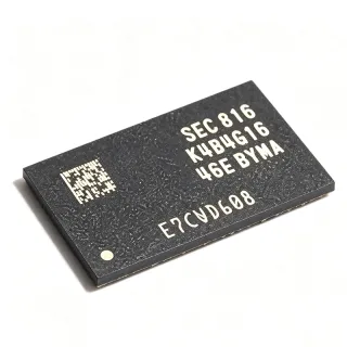
K6X4008C1F-MF55 - 512Kx8 4Mbit 55ns SRAM | Samsung
MPN: K6X4008C1F-MF55 ✗ End of Life| Qty | Unit Price | Extended |
|---|---|---|
| 1 | $4.5 | $4.50 |
| 10 | $4.05 | $40.50 |
| 100 | $3.6 | $360.00 |
| 500 | $3.15 | $1,575.00 |
| 1,000 | $2.7 | $2,700.00 |
K6X4008C1F-MF55 Overview
An asynchronous SRAM is a type of volatile semiconductor memory that stores data in six-transistor flip-flop cells and communicates over a parallel address and data bus without requiring a clock. Within the memory IC hierarchy, it sits under standard SRAM -> RAM -> memory IC -> integrated circuits. Asynchronous SRAMs are prized for deterministic, clockless read and write timing, making them easy to interface to legacy microprocessors, microcontrollers, and FPGA glue-logic designs.
Key features of the K6X4008C1F include the full CMOS process technology, an ultra-low-power standby mode with data retention down to a low data-retention voltage, and fast 55 ns address access time. Three control pins (CE, OE, WE) give flexible bus interfacing, and the 5V rail eliminates the need for level shifting in legacy 5V systems.
Technically, the device is organized as 524,288 words x 8 bits and fabricated on Samsung's advanced full CMOS process, which reduces both active and standby current compared with NMOS-era SRAMs. The family datasheet notes support for various operating temperature ranges and multiple package types for system design flexibility, plus battery-backup-friendly low data-retention current for non-volatile operation with a lithium cell.
Typical applications include legacy PC and industrial controller expansion memory, embedded microprocessor buffers, telecom line-card scratchpad memory, MSX and retro-computing board rebuilds, and any 5V system requiring a parallel 4 Mbit static buffer.
A key design consideration is power dissipation and bus timing: at 55 ns the device supports fast CPU buses, but designers must respect CE/OE/WE timing margins and decouple the 5V rail with at least 0.1 uF ceramic capacitance per package.
This page synthesizes distributor availability, family drop-in alternatives, practical design notes, and pin-compatibility guidance not found in a single manufacturer datasheet.
Drop-in alternatives for K6X4008C1F-MF55 — same package, pin-to-pin compatible. Different-package parts requiring PCB rework are excluded.
Variants in this series
Same-series models that are drop-in compatible with K6X4008C1F-MF55 (same form factor and footprint) — differing in Data Retention, Memory Type, Organization, Package.
Quick Comparison Tool — Select alternative parts for side-by-side comparison:
K6X4008C1F-UF55
✅ Drop-In📋 Reference alternative (not in catalog)
K6X4008C1F-MF70
✅ Drop-In ⚠️ Specs Unverified📋 Reference alternative (not in catalog)
K6X4008C1F-UF70
✅ Drop-In ⚠️ Specs Unverified📋 Reference alternative (not in catalog)
KM684000CL-55
✅ Drop-In ⚠️ Specs Unverified📋 Reference alternative (not in catalog)
KM684000BL-55
✅ Drop-In ⚠️ Specs Unverified📋 Reference alternative (not in catalog)
K6X4008C1F-MF55 Maximum Ratings & Electrical Characteristics
| Memory Type | SRAM - Asynchronous |
| Organization | 512K x 8 bit |
| Memory Size | 4 Mbit |
| Access Time | 55 ns |
| Interface | Parallel |
| Supply Voltage | 5 V |
| Technology | Full CMOS |
| Package | TSOP2-32 (0.400 inch, REVERSE) |
| Mounting Type | Surface Mount |
| Data Retention | Supported, low data retention voltage/current for battery backup |
| Control Signals | CE, OE, WE |
| Address Lines | 19 (A0-A18) |
| Data Lines | 8 (I/O1-I/O8) |
K6X4008C1F-MF55 Pin Configuration
| Pin 1 | CE — Chip Enable (active low) |
| Pin 2 | A16 — Address input 16 |
| Pin 3 | A15 — Address input 15 |
| Pin 4 | A17 — Address input 17 |
| Pin 5 | OE — Output Enable (active low) |
| Pin 6 | A14 — Address input 14 |
| Pin 7 | A13 — Address input 13 |
| Pin 8 | A12 — Address input 12 |
| Pin 9 | A11 — Address input 11 |
| Pin 10 | A10 — Address input 10 |
| Pin 11 | A9 — Address input 9 |
| Pin 12 | A8 — Address input 8 |
| Pin 13 | VCC — Power supply (+5 V) |
| Pin 14 | I/O1 — Data input/output bit 1 |
| Pin 15 | I/O2 — Data input/output bit 2 |
| Pin 16 | I/O3 — Data input/output bit 3 |
| Pin 17 | I/O4 — Data input/output bit 4 |
| Pin 18 | I/O5 — Data input/output bit 5 |
| Pin 19 | I/O6 — Data input/output bit 6 |
| Pin 20 | I/O7 — Data input/output bit 7 |
| Pin 21 | I/O8 — Data input/output bit 8 |
| Pin 22 | GND — Ground |
| Pin 23 | A7 — Address input 7 |
| Pin 24 | A6 — Address input 6 |
| Pin 25 | A5 — Address input 5 |
| Pin 26 | A4 — Address input 4 |
| Pin 27 | A3 — Address input 3 |
| Pin 28 | A2 — Address input 2 |
| Pin 29 | A1 — Address input 1 |
| Pin 30 | A0 — Address input 0 |
| Pin 31 | A18 — Address input 18 |
| Pin 32 | WE — Write Enable (active low) |
Typical Applications
K6X4008C1F-MF55 is suitable for 6 applications: Legacy Industrial Controller Memory, Retro Computing and MSX Board Repair, Telecom and Networking Line Cards, Battery-Backed Data Retention Systems, Embedded Microprocessor Systems (5V buses), Test and Measurement Instrument Buffers.
Legacy Industrial Controller Memory
The K6X4008C1F-MF55 fits 5V industrial PLC, motor-controller, and instrumentation designs that were laid out in the 1990s-2000s era of 5V microprocessors. Its 4 Mbit (512K x 8) organization matches common external-memory maps for 80186, 68HC000, and early 80C32-class CPUs, while the 55 ns access time covers buses up to roughly 25 MHz with standard address-decode margins. Used as the processor's external data/scratchpad RAM between the CPU data bus and an address latch (e.g., 74HC573) plus a PLD-generated CE signal, it drops onto the original footprint during service repairs, keeping EOL industrial equipment alive without PCB redesign. Low data-retention current also enables battery-backed parameter storage.
Recommended
Retro Computing and MSX Board Repair
Retro-computing communities, notably the MSX Resource Center forum, actively use K6X4008C1F parts as replacements for the Samsung KM684000 SRAM in MSX machines, arcade boards, and 8/16-bit home computers. The 5V rail, 512K x 8 organization, and asynchronous parallel interface map directly onto Z80 (3.5 MHz) and similar CPU designs, where the 55 ns access time provides generous timing margin. Repairers should verify package orientation because the -MF55 uses a REVERSE TSOP2 footprint; the community thread 'K6X4008C1F instead of KM684000 for SRAM?' confirms real-world success with attention to pin 1 placement. Battery-backed save-RAM cartridge designs also benefit from the family's low data-retention voltage.
Recommended
Telecom and Networking Line Cards
Older telecom line cards and network interface boards used 5V asynchronous SRAM as fast buffering between line-processing ASICs and control CPUs. The K6X4008C1F-MF55's deterministic 55 ns clockless access simplifies timing analysis in TDM-style buffers, avoiding the latency uncertainty of DRAM solutions. Its full CMOS process keeps active current low compared with NMOS-era predecessors, reducing per-card power budgets in high-slot-count shelves, and the low data-retention current supports battery-backed configuration storage during shelf power events. Because many of these shelves remain in service for decades, the TSOP2-32 footprint replacement with the same-family UF55 variant is a standard maintenance practice for legacy telecom hardware operators.
Recommended
Battery-Backed Data Retention Systems
The K6X4008C1F family explicitly supports 'low data retention voltage for battery back-up operation with low data retention current' per the Samsung family datasheet, making the -MF55 suitable for metering, gaming, and data-logging equipment that must preserve state through power loss. In a typical circuit, the CE pin is monitored by a supervisor; when VCC falls below threshold, CE is held near the retention voltage while a lithium coin cell takes over the array. Full CMOS cells then draw microamp-level retention current, extending coin-cell life for years. The 55 ns operating performance returns instantly when main power is restored, with no software re-initialization required, which is a decisive advantage over Flash-based state storage for fast-cycling equipment.
Recommended
Embedded Microprocessor Systems (5V buses)
For 5V embedded designs such as industrial gateways, test fixtures, and automotive diagnostics tools built around 5V MCUs, the K6X4008C1F-MF55 provides external RAM without any level-shifting circuitry. The parallel 8-bit bus connects directly to processor pins, and the three-signal CE/OE/WE interface is generated by simple decode logic, keeping BOM count minimal. The 55 ns access time supports 0-wait-state operation for many 16-bit embedded CPUs up to about 20 MHz. Compared with a parallel DRAM alternative, this SRAM needs no refresh controller and has constant access latency, which matters for hard real-time ISRs that store state in external memory during time-critical events.
Recommended
Test and Measurement Instrument Buffers
Bench instruments - logic analyzers, EPROM programmers, universal device programmers, and pattern generators - from the 5V era rely on fast, deterministic SRAM as sample or buffer memory. The K6X4008C1F-MF55's 55 ns asynchronous access lets capture hardware stream 8-bit samples without handshake delays, and the 512K x 8 depth matches typical capture windows of that generation. Service technicians repairing such instruments value the direct TSOP2-32 REVERSE footprint compatibility with original boards. The full CMOS design also tolerates the repeated power-cycling typical of instrument bench use, with no refresh logic and negligible warm-up behavior, keeping repair turnaround fast and calibration procedures unaffected by memory replacement.
Recommended
Recommended Products Summary
Engineering reference data for K6X4008C1F-MF55 — comparison, design guidance, and compliance information.
Selection Guide
Comparison with Alternatives
| Parameter | This Product | K6X4008C1F-UF55 | K6X4008C1F-MF70 | K6X4008C1F-UF70 | KM684000CL-55 | KM684000BL-55 |
|---|---|---|---|---|---|---|
| Package | TSOP2-32 (0.400 in, REVERSE) | TSOP2-32 REVERSE - same | TSOP2-32 REVERSE - same | TSOP2-32 REVERSE - same | TSOP2-32 - verify orientation | TSOP2-32 - verify orientation |
| Brand | Samsung Electronics | Samsung Electronics | Samsung Electronics | Samsung Electronics | Samsung Electronics | Samsung Electronics |
| Organization | 512K x 8 | 512K x 8 | 512K x 8 | 512K x 8 | 512K x 8 | 512K x 8 |
| Memory Size | 4 Mbit | 4 Mbit | 4 Mbit | 4 Mbit | 4 Mbit | 4 Mbit |
| Access Time | 55 ns | 55 ns | 70 ns | 70 ns | 55 ns | 55 ns |
| Supply Voltage | 5 V | 5 V | 5 V | 5 V | 5 V | 5 V |
| Battery Data Retention | Yes (low retention V/I) | Yes | Yes | Yes | Yes | Yes |
| Lifecycle Status | EOL | EOL | EOL | EOL | EOL | EOL |
Key Differentiators
- Identical 55 ns speed in same-family swap (vs K6X4008C1F-UF55)
- Faster than 70 ns family grades (vs K6X4008C1F-MF70)
- Modern CMOS process vs predecessor (vs KM684000CL-55)
Design Notes
The -MF55 uses a REVERSE-orientation TSOP2-32 (0.400 inch) package: pin 1 (CE) sits at the opposite corner relative to a standard TSOP2. Before placing this part on a board laid out for KM684000 or other standard-orientation SRAMs, rotate the footprint or confirm that the silkscreen pin-1 dot matches the package chamfer. Mis-insertion of a 32-pin TSOP reverses VCC and GND and will destroy the device on power-up. This is the single most common failure mode reported when substituting between Samsung SRAM families.
Estimated: with a 5V rail and full CMOS SRAM cells, decouple each package with 0.1 uF ceramic placed within 5 mm of VCC (pin 13) plus a 10 uF bulk capacitor per bus segment. During battery-backup operation, hold CE near the retention voltage rather than floating it; the family datasheet specifies low data-retention voltage and current for this mode, which is what enables multi-year coin-cell life. Ensure the backup supervisor switches CE before VCC collapses to avoid corruption of the last write cycle.
For new designs, do not design in an EOL part. The K6X4008C1F-MF55 is discontinued and available only from excess-inventory channels with mixed lot dates. Verify bus timing against your speed grade: substituting a 70 ns (-70) part for a 55 ns (-55) part on a 20+ MHz CPU bus without re-checking address-access margin will produce intermittent, temperature-dependent failures. Also confirm address line count: 19 address lines (A0-A18) are required for the full 512K x 8 range; grounding A18 restricts decoding to 256K.
Compliance Information
EOL Samsung part; RoHS/lead-free status varies by production date and is not consistently published on distributor pages. Request certificate of conformance for the specific lot before purchase.