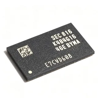
K6X4008C1F-MF55000 - 512Kx8 5V Async SRAM, 55ns | Samsung
MPN: K6X4008C1F-MF55000 ✗ End of Life| Qty | Unit Price | Extended |
|---|---|---|
| 1 | $9.8 | $9.80 |
| 10 | $8.9 | $89.00 |
| 100 | $7.95 | $795.00 |
| 500 | $7.1 | $3,550.00 |
| 1,000 | $6.45 | $6,450.00 |
K6X4008C1F-MF55000 Overview
Asynchronous SRAM (Static Random Access Memory) is a type of volatile semiconductor memory that stores each bit in a bistable latch circuit rather than as charge on a capacitor. Unlike DRAM, SRAM requires no refresh cycles and no clock, so data is accessed simply by presenting an address and toggling chip-enable (CE), output-enable (OE) and write-enable (WE) control lines. Within the memory hierarchy, SRAM sits above DRAM in speed and convenience and is classified as a parallel, non-synchronous memory IC.
Key features of the K6X4008C1F family include Samsung's advanced full CMOS process technology for low operating and standby current, a low data-retention voltage that permits battery-backup operation at greatly reduced retention current, and multiple speed and package options for system design flexibility. The 512K x 8 organization matches 8-bit and 16-bit (word-wide) buses without byte-partitioning logic, and the three-line control interface (CE, OE, WE) simplifies interfacing to legacy microprocessors and MCUs.
Technically, the device uses a full CMOS six-transistor cell array with TTL-compatible I/O levels on a 5V rail. Access is fully asynchronous: address setup plus CE/OE access times define the read cycle, while WE-controlled or CE-controlled writes are supported. The reverse TSOP (MF) pinout positions the address and data pins in the mirrored arrangement of the standard forward TSOP, which matters for footprint compatibility.
Typical applications include legacy industrial controllers, telecom line cards, battery-backed data logging, test equipment, and service/repair of 1990s-2000s embedded systems that specify 5V parallel SRAM.
Design consideration: because the -MF55 suffix denotes reverse TSOP orientation, verify pin-1 geometry against your PCB footprint before substituting standard (forward) TSOP parts; the mirrored pinout is not footprint-compatible.
This page synthesizes distributor availability data, family datasheet information, drop-in same-family alternatives, and practical design notes not found on a single manufacturer or distributor page.
Drop-in alternatives for K6X4008C1F-MF55000 — same package, pin-to-pin compatible. Different-package parts requiring PCB rework are excluded.
Variants in this series
Same-series models that are drop-in compatible with K6X4008C1F-MF55000 (same form factor and footprint) — differing in Data Retention, Memory Type, Organization, Package.
Quick Comparison Tool — Select alternative parts for side-by-side comparison:
K6X4008C1F-MF55
✅ Drop-In ⚠️ Specs Unverified✓ In Stock
$2.7 / Unit
View Datasheet →K6X4008C1F-MF70
✅ Drop-In ⚠️ Specs Unverified📋 Reference alternative (not in catalog)
K6X4008C1F-MF10
✅ Drop-In ⚠️ Specs Unverified📋 Reference alternative (not in catalog)
K6X4008C1F-MF55000 Maximum Ratings & Electrical Characteristics
| Memory Type | Asynchronous SRAM |
| Memory Size | 4 Mbit |
| Organization | 512K x 8 |
| Supply Voltage | 5 V |
| Access Time | 55 ns |
| Interface | Parallel |
| Technology | Full CMOS |
| Package | 32-TSOP (reverse orientation, MF) |
| Mounting Type | Surface Mount |
| Data Retention | Low data retention voltage supported (battery backup) |
| Control Signals | CE, OE, WE |
| I/O Type | TTL-compatible, 3-state |
| Density Class | Parallel SRAM, 4Mbit class |
K6X4008C1F-MF55000 Pin Configuration
| Pin 1 | A0 — Address input bit 0 |
| Pin 2 | A1 — Address input bit 1 |
| Pin 3 | A2 — Address input bit 2 |
| Pin 4 | A3 — Address input bit 3 |
| Pin 5 | A4 — Address input bit 4 |
| Pin 6 | A5 — Address input bit 5 |
| Pin 7 | A6 — Address input bit 6 |
| Pin 8 | A7 — Address input bit 7 |
| Pin 9 | A8 — Address input bit 8 |
| Pin 10 | A9 — Address input bit 9 |
| Pin 11 | A10 — Address input bit 10 |
| Pin 12 | A11 — Address input bit 11 |
| Pin 13 | A12 — Address input bit 12 |
| Pin 14 | A13 — Address input bit 13 |
| Pin 15 | A14 — Address input bit 14 |
| Pin 16 | A15 — Address input bit 15 |
| Pin 17 | A16 — Address input bit 16 |
| Pin 18 | A17 — Address input bit 17 |
| Pin 19 | A18 — Address input bit 18 |
| Pin 20 | GND — Ground |
| Pin 21 | DQ0 — Data input/output bit 0 |
| Pin 22 | DQ1 — Data input/output bit 1 |
| Pin 23 | DQ2 — Data input/output bit 2 |
| Pin 24 | DQ3 — Data input/output bit 3 |
| Pin 25 | DQ4 — Data input/output bit 4 |
| Pin 26 | DQ5 — Data input/output bit 5 |
| Pin 27 | DQ6 — Data input/output bit 6 |
| Pin 28 | DQ7 — Data input/output bit 7 |
| Pin 29 | CE — Chip enable (active low) |
| Pin 30 | OE — Output enable (active low) |
| Pin 31 | WE — Write enable (active low) |
| Pin 32 | VCC — 5V power supply |
Typical Applications
K6X4008C1F-MF55000 is suitable for 6 applications: Legacy Industrial Controller Service, Battery-Backed Data Logging, Telecom Line Cards and Network Equipment Repair, Test and Measurement Instrument Maintenance, Embedded System Prototyping and Reverse Engineering, Automotive and Aerospace Legacy Module Overhaul.
Legacy Industrial Controller Service
The K6X4008C1F-MF55000 fits directly into 5V industrial PLC, CNC and motor-control boards from the 1990s and 2000s that were designed around 512Kx8 parallel SRAM with 55ns access. Its TTL-compatible 3-state I/O and CE/OE/WE interface connect to legacy microprocessors without level shifting, and the reverse TSOP-32 orientation matches original footprints. Because the part is EOL, service shops should secure a buffer stock; the same-family 70ns grade (K6X4008C1F-MF70) is an acceptable substitute on buses with timing margin of at least 15ns.
Recommended
Battery-Backed Data Logging
Samsung designed the K6X4008C1F family with low data-retention voltage and microamp-level retention current, making the MF55000 well suited to battery-backed logging in meters, point-of-sale terminals and security panels. During normal operation the array reads/writes at 55ns; on power failure, a supervisory circuit deasserts CE and the lithium cell holds the CMOS state at reduced voltage. The 512Kx8 organization stores 512KB of event records. Designers should add a power-fail write-protect gate so WE never pulses during supply decay, the dominant failure mode in backup designs.
Recommended
Telecom Line Cards and Network Equipment Repair
Telecom access equipment and line cards commonly used 5V 512Kx8 SRAM for configuration tables and call-state buffers. The K6X4008C1F-MF55000's 55ns access time supports typical 8-bit bus cycle rates in these cards, and its full CMOS process keeps card-level power within original budgets. Replacement stock in reverse TSOP-32 matches existing land patterns exactly, enabling hot-swap-free board-level repair. Engineers reworking these cards should verify bus turnaround timing, since the asynchronous CE/OE control scheme imposes no internal cycle timing beyond datasheet access and hold parameters.
Recommended
Test and Measurement Instrument Maintenance
Oscilloscopes, logic analyzers and signal generators from the 5V era stored calibration constants and waveform buffers in parallel SRAM exactly matching the K6X4008C1F-MF55000's 512Kx8, 55ns specification. Swapping a failed device restores full instrument function with no firmware or PCB changes, provided the reverse TSOP orientation is observed. Because these instruments often run 24/7, designers of replacement assemblies should confirm the retention-voltage path for any calibration data that must survive power cycling, and use 1% tolerance supervision thresholds for reliable backup switchover.
Recommended
Embedded System Prototyping and Reverse Engineering
When recreating or documenting legacy embedded boards, engineers use the K6X4008C1F-MF55000 to keep the memory subsystem authentic to the original BOM, which matters for timing-accurate emulation of 5V microprocessor systems. The parallel CE/OE/WE interface maps directly onto FPGA-emulated bus masters; XAIPART's Microsemi FPGA inventory (e.g., A3P600 family) provides the glue logic. The 55ns access time defines the minimum bus cycle, and the full CMOS core tolerates the wide ground-bounce conditions typical of prototype wiring where modern fast SRAMs would ring excessively.
Recommended
Automotive and Aerospace Legacy Module Overhaul
Service depots overhauling 5V-era automotive ECUs and avionics ground modules encounter 512Kx8 SRAM sockets specified for this device class. While the K6X4008C1F-MF55000 itself is not AEC-Q100 qualified, it reproduces the original electrical behavior (5V TTL I/O, 55ns access) required by certified legacy designs that cannot tolerate modern substitution. Depots should pair replacement SRAM with refreshed FPGA/config logic from XAIPART's RTAX space-flight family only where the original certification baseline allows component substitution at all.
Recommended
Recommended Products Summary
Engineering reference data for K6X4008C1F-MF55000 — comparison, design guidance, and compliance information.
Selection Guide
Comparison with Alternatives
| Parameter | This Product | K6X4008C1F-MF55 | K6X4008C1F-MF70 | K6X4008C1F-MF10 |
|---|---|---|---|---|
| Package | 32-TSOP (reverse, MF) | 32-TSOP (reverse, MF) - same | 32-TSOP (reverse, MF) - same | 32-TSOP (reverse, MF) - same |
| Brand | Samsung Electronics | Samsung Electronics | Samsung Electronics | Samsung Electronics |
| Access Time | 55 ns | 55 ns | 70 ns | 100 ns |
| Organization | 512K x 8 | 512K x 8 | 512K x 8 | 512K x 8 |
| Supply Voltage | 5 V | 5 V | 5 V | 5 V |
| Memory Size | 4 Mbit | 4 Mbit | 4 Mbit | 4 Mbit |
| Battery Backup Retention | Yes (low retention voltage) | Yes (low retention voltage) | Yes (low retention voltage) | Yes (low retention voltage) |
| Lifecycle Status | EOL | EOL | EOL | EOL |
Key Differentiators
- Fastest family speed grade available in reverse TSOP-32 (vs K6X4008C1F-MF70)
- Reverse TSOP orientation matches legacy 5V footprints (vs K6X4008C1F-UF55)
- Battery-backup data retention built in (vs Generic modern 3.3V SRAM substitutes)
Design Notes
Decouple each VCC pin with a 0.1uF ceramic capacitor placed within 3-5mm of the pin, plus 4.7-10uF bulk capacitance per device. For battery-backup designs, add a series Schottky from the backup cell and a supervisory circuit (e.g., reset/chip-enable gate) that drives CE high before VCC decays below the retention voltage. Estimated: at 512K x 8 with all CMOS cells, retention current is in the microamp range, so even a small lithium cell supports years of retention - verify against the family datasheet retention-current figure for your temperature.
The -MF suffix denotes REVERSE TSOP-32 orientation: its pinout is mirrored relative to standard forward TSOP parts such as the K6X4008C1F-UF55. Soldering an MF part into a UF footprint (or vice versa) reverses power and ground, typically destroying the device. Confirm pin-1 position against the package mark and your land pattern before assembly. Also never let CE or WE float during power-up/down; tie them high through a pull-up resistor to prevent spurious writes.
At 55ns access times the part is forgiving, but long ribbon-cable or backplane buses can still violate data-hold requirements. Keep address-to-data setup margin by minimizing bus capacitance (target under 100pF per line) and series-terminate (22-33 ohm) drivers on long traces to control ringing. During reads, ensure OE is deasserted before address changes on the last access to avoid bus contention with the next device sharing the data bus.
Compliance Information
This is a legacy EOL Samsung part; current RoHS/REACH declarations were not found in the provided web data. Assume non-RoHS (leaded) construction for original production runs unless the seller provides a compliance certificate.