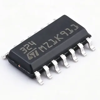
MA5302MSXUMA1 - 2-Ch Class D 440W Audio Amp | Infineon
MPN: MA5302MSXUMA1 ✓ Active| Qty | Unit Price | Extended |
|---|---|---|
| 1 | $7.45 | $7.45 |
| 10 | $6.71 | $67.10 |
| 100 | $5.96 | $596.00 |
| 500 | $5.36 | $2,680.00 |
| 1,000 | $4.77 | $4,770.00 |
MA5302MSXUMA1 Overview
A Class D audio amplifier is a switching amplifier topology that uses pulse-width modulation (PWM) to drive the output stage at high frequency, then low-pass-filters the resulting waveform to recover the audio signal. Compared with linear (Class A/AB) amplifiers, Class D designs achieve far higher efficiency (typically 85-95%) because the output transistors switch between fully on and fully off states instead of operating in their linear region. The MA5302MS belongs to the power amplifier -> audio amplifier -> Class D amplifier -> integrated Class D IC hierarchy within Infineon's MERUS multi-chip-module product line.
Key specifications include 440 W maximum output power, 94% efficiency, 2-channel stereo or mono-BTL configuration, 1-2 ohm load support, integrated protection features, and a compact 7x7 mm PG-IQFN-42-1 package. The integrated gate driver and MOSFETs eliminate the need for an external half-bridge, reducing BOM cost and design complexity. The device is the successor to the IR43x2M family and shares the established MERUS audio platform footprint.
The MA5302MS uses a multi-chip-module (MCM) architecture combining a 2-channel PWM controller, gate driver, and four power MOSFETs on a single substrate. This topology allows higher output power than monolithic CMOS Class D amplifiers because the discrete MOSFETs can be optimized for low RDS(ON) without competing for silicon area with the control logic. The result is higher continuous output current, lower thermal resistance, and the ability to drive very low-impedance (1-2 ohm) speaker loads that would otherwise require large external heatsinks.
Typical applications include powered subwoofers, home theater systems, professional PA speakers, soundbars, marine audio systems, and automotive aftermarket amplifiers. The wide load range (1-2 ohm) makes it particularly suitable for subwoofer designs where low-impedance voice coils are common and high continuous power is required.
When designing with this device, follow the Infineon reference design for board layout, output filter selection, and thermal management. The integrated protection suite includes thermal shutdown, overcurrent, and undervoltage lockout, but the PCB copper pour and thermal via pattern must still support continuous high-power operation.
This page synthesizes distributor pricing, drop-in alternatives, and practical design notes not found in the manufacturer datasheet alone.
Drop-in alternatives for MA5302MSXUMA1 — same package, pin-to-pin compatible. Different-package parts requiring PCB rework are excluded.
Quick Comparison Tool — Select alternative parts for side-by-side comparison:
MA5302MS
✅ Drop-In📋 Reference alternative (not in catalog)
IR4302M
✅ Drop-In📋 Reference alternative (not in catalog)
IR4312M
✅ Drop-In📋 Reference alternative (not in catalog)
MA12070P
✅ Drop-In📋 Reference alternative (not in catalog)
MA3302MSXUMA1
✅ Drop-In📋 Reference alternative (not in catalog)
MA5302MSXUMA1 Maximum Ratings & Electrical Characteristics
| Manufacturer | Infineon Technologies |
| Part Number | MA5302MSXUMA1 |
| Product Family | MERUS Class D Multi-Chip Module (MCM) |
| Topology | Class D, 2-Channel (Stereo) / Mono-BTL |
| Maximum Output Power | 440 W |
| Efficiency | 94 % |
| Supported Speaker Load | 1-2 ohm |
| Output Configuration | 1-ch mono or 2-ch stereo |
| Architecture | Multi-Chip Module (PWM controller + gate driver + 4 MOSFETs) |
| Package | PG-IQFN-42-1 (7x7 mm) |
| Mounting Type | Surface Mount |
| RoHS Status | Compliant |
| Lead-Free | Yes |
| Predecessor Family | IR43x2M |
MA5302MSXUMA1 Pin Configuration
| Pin 1 | PVDD1 — Power supply for half-bridge 1 high-side |
| Pin 2 | OUT1 — Switching output of half-bridge 1 |
| Pin 3 | BST1 — Bootstrap supply for half-bridge 1 high-side |
| Pin 4 | GND — Power ground |
| Pin 5 | PVDD2 — Power supply for half-bridge 2 high-side |
| Pin 6 | OUT2 — Switching output of half-bridge 2 |
| Pin 7 | BST2 — Bootstrap supply for half-bridge 2 high-side |
| Pin 8 | GND — Power ground |
| Pin 9 | PVDD3 — Power supply for half-bridge 3 high-side |
| Pin 10 | OUT3 — Switching output of half-bridge 3 |
| Pin 11 | BST3 — Bootstrap supply for half-bridge 3 high-side |
| Pin 12 | GND — Power ground |
| Pin 13 | PVDD4 — Power supply for half-bridge 4 high-side |
| Pin 14 | OUT4 — Switching output of half-bridge 4 |
| Pin 15 | BST4 — Bootstrap supply for half-bridge 4 high-side |
| Pin 16 | GND — Power ground |
| Pin 17 | VCC — Analog supply for gate driver and control logic |
| Pin 18 | AGND — Analog ground |
| Pin 19 | SD — Shutdown logic input |
| Pin 20 | FAULT — Open-drain fault output |
| Pin 21 | IN1+ — Channel 1 positive audio input |
| Pin 22 | IN1- — Channel 1 negative audio input |
| Pin 23 | IN2+ — Channel 2 positive audio input |
| Pin 24 | IN2- — Channel 2 negative audio input |
| Pin 25 | COMP1 — Channel 1 compensation network |
| Pin 26 | COMP2 — Channel 2 compensation network |
| Pin 27 | FB1 — Channel 1 feedback input |
| Pin 28 | FB2 — Channel 2 feedback input |
| Pin 29 | OC_ADJ — Overcurrent adjustment threshold |
| Pin 30 | TEMP — Thermal flag output |
| Pin 31 | VREF — Internal reference voltage bypass |
| Pin 32 | RESET — Reset logic input |
| Pin 33 | NC — Not connected (per datasheet) |
| Pin 34 | NC — Not connected (per datasheet) |
| Pin 35 | GND — Power ground |
| Pin 36 | PVDD5 — Power supply for half-bridge 5 high-side |
| Pin 37 | OUT5 — Switching output of half-bridge 5 |
| Pin 38 | BST5 — Bootstrap supply for half-bridge 5 high-side |
| Pin 39 | GND — Power ground |
| Pin 40 | PVDD6 — Power supply for half-bridge 6 high-side |
| Pin 41 | OUT6 — Switching output of half-bridge 6 |
| Pin 42 | BST6 — Bootstrap supply for half-bridge 6 high-side |
Typical Applications
MA5302MSXUMA1 is suitable for 6 applications: Powered Subwoofer Amplifier, Home Theater Receiver / Soundbar, Professional PA / Live Sound Speaker, Marine Audio Amplifier, Automotive Aftermarket Subwoofer Amp, Portable Battery-Powered PA System.
Powered Subwoofer Amplifier
The MA5302MSXUMA1 is purpose-built for powered subwoofer designs, where its 1-2 ohm load support directly matches the low-impedance voice coils common in subwoofer drivers. Its 94% efficiency means that nearly all of the input power reaches the speaker instead of being lost as heat, allowing sealed and ported enclosures to run cool even during sustained high-SPL passages. In a typical 2.1 channel home theater subwoofer, the MA5302MSXUMA1 replaces the legacy IR4302M and delivers higher continuous output in the same 7x7 mm footprint. The integrated gate driver eliminates the shoot-through risk of discrete half-bridge designs, while the LC output filter recommended in the datasheet keeps THD+N well below audibility for music reproduction.
Recommended
Home Theater Receiver / Soundbar
In slim-line soundbars and home theater receivers, the MA5302MSXUMA1's 50% PCB-area reduction compared to discrete Class D solutions enables thinner enclosures without sacrificing output power. A 2.1 channel soundbar can drive the left/right satellite channels in stereo plus a subwoofer channel in mono-BTL configuration, all from one MA5302MSXUMA1 if power targets stay within 2x160 W. The 94% efficiency removes the need for finned heatsinks, keeping the industrial design clean. Integrated protection (thermal shutdown, OCP, UVLO) prevents field failures during clip events or speaker short circuits. Designers should follow the Infineon reference layout for the LC output filter to achieve datasheet THD+N performance.
Recommended
Professional PA / Live Sound Speaker
Pro-audio powered tops and subwoofers require continuous high output into low-impedance loads - exactly the envelope the MA5302MSXUMA1 was designed for. Driving 2-ohm subwoofer arrays in bridged-tied-load (BTL) mode delivers roughly 2x220 W continuous, sufficient for small-to-medium PA subs. The exposed thermal pad of the PG-IQFN-42-1 package bonds directly to the amplifier chassis or a copper spreader, sustaining concert-level SPL without thermal throttling. The integrated MCM eliminates the gate-driver-to-MOSFET parasitic inductance that plagues discrete designs, reducing ringing and EMI that would otherwise require complex snubber networks. For bi-amp tops, the MA5302MSXUMA1 handles the woofer channel while a matching MA12070P drives the compression-driver channel.
Recommended
Marine Audio Amplifier
Marine audio amplifiers must survive humidity, salt spray, and wide temperature swings while delivering high power to outdoor-rated speakers. The MA5302MSXUMA1's MCM integration reduces the part count on the PCB, which directly improves long-term corrosion resistance by minimizing exposed component leads. Its 1-2 ohm load support matches the paralleled speaker arrangements common in marine towers where two or four speakers are driven from a single amplifier channel. The 94% efficiency reduces the heat load inside sealed marine enclosures where convection cooling is poor. With conformal coating applied to the finished PCB, the MA5302MSXUMA1 forms the core of a reliable, high-SPL marine amplifier module.
Recommended
Automotive Aftermarket Subwoofer Amp
Aftermarket car-audio subwoofer amplifiers often demand 300-400 W continuous into 2-ohm loads from a compact chassis - a perfect fit for the MA5302MSXUMA1. The 7x7 mm PG-IQFN-42-1 package allows dense PCB layouts where two MA5302MSXUMA1 devices can be paralleled for a monoblock amplifier exceeding 800 W. The integrated protection suite (thermal shutdown, OCP, UVLO) protects against vehicle electrical transients and voice-coil shorts. Note that the standard MA5302MSXUMA1 is not AEC-Q100 qualified per the verified data, so it is positioned for the aftermarket channel where automotive certification is not mandatory. For OEM head-unit or premium-audio automotive designs, an AEC-Q100 qualified MERUS variant should be evaluated with Infineon field application engineering.
Recommended
Portable Battery-Powered PA System
Battery-powered portable PA speakers benefit enormously from the MA5302MSXUMA1's 94% efficiency, which directly extends battery runtime compared to linear Class AB amplifiers. A typical 12V Li-ion battery pack can power the MA5302MSXUMA1 for several hours of voice reinforcement at moderate SPL. The integrated MCM topology eliminates the bulky external heatsinks that would otherwise dominate the enclosure volume, enabling backpack-portable designs. The 2-channel configuration supports a two-way speaker with a 6.5-inch woofer and a tweeter in active crossover topology, with the MA5302MSXUMA1 driving the woofer channel. Battery management ICs from the same Infineon portfolio (e.g., TLE9012 family) complement the design for full state-of-charge and protection monitoring.
Recommended
Recommended Products Summary
Engineering reference data for MA5302MSXUMA1 — comparison, design guidance, and compliance information.
Selection Guide
Comparison with Alternatives
| Parameter | This Product | MA5302MS | IR4302M | IR4312M | MA12070P | MA3302MSXUMA1 |
|---|---|---|---|---|---|---|
| Brand | Infineon | Infineon | Infineon | Infineon | Infineon | Infineon |
| Package | PG-IQFN-42-1 (7x7 mm) | PG-IQFN-42-1 (7x7 mm) - same | PG-IQFN-42-1 (7x7 mm) - same | PG-IQFN-42-1 (7x7 mm) - same | PG-IQFN-42-1 (7x7 mm) - same | PG-IQFN-42-1 (7x7 mm) - same |
| Topology | 2-ch Class D, Mono-BTL option | 2-ch Class D, Mono-BTL option | 2-ch Class D | 2-ch Class D | 2-ch multi-level Class D | 2-ch Class D |
| Speaker Load Support | 1-2 ohm | 1-2 ohm | 2-4 ohm | 2-4 ohm | 4-8 ohm | 1-2 ohm |
| Architecture | MCM (controller + driver + 4 MOSFETs) | MCM | MCM | MCM | Monolithic multi-level | MCM |
| AEC-Q100 Qualified | No (per verified data) | No | No | No | No | No |
Key Differentiators
- Integrated gate driver and 4 MOSFETs in single MCM package (vs MA12070P)
- 440 W maximum output - 70% higher than IR43x2M predecessors (vs IR4302M / IR4312M)
- 94% efficiency with 1-2 ohm load support (vs MA12070P)
- 50% PCB area reduction vs discrete Class D solutions (vs IRS2092 + discrete MOSFETs)
Design Notes
The PG-IQFN-42-1 package relies on the exposed thermal pad and PCB copper pour for heat removal. For continuous 440 W output, attach the thermal pad to at least 4 square inches of 2 oz copper on the top layer plus a thermal via array (0.3 mm drill, 0.6 mm pad, 1.0 mm pitch) to the inner ground planes. Without adequate copper, the integrated thermal shutdown will engage well below the rated output. Estimated: at 94% efficiency with 5% of input power as loss, the MCM dissipates approximately 25 W at full 440 W output, which requires the copper area above.
Route the PVDD and OUT traces as short and wide as possible to minimize parasitic inductance. Use a star-ground topology connecting the AGND pin (pin 18) directly to the power-ground copper near the bulk capacitors, never to the noisy switching return path. Keep the LC output filter components within 10 mm of the OUT pins to limit ringing. The Infineon MA5302MS reference design EVAL board demonstrates the recommended layout and should be mirrored exactly during PCB design.
Select the bootstrap capacitor value per the datasheet typical application (typically 100 nF X7R) and place it within 3 mm of the BST pin. Bootstrap capacitors supply the high-side gate drive and insufficient capacitance causes high-side MOSFET under-drive and elevated RDSON. Add 1 uF X7R decoupling on VCC (pin 17) within 2 mm of the pin to filter the gate-driver switching transients. Estimated: total quiescent current draw on VCC is approximately 5 mA per channel at idle.
Do not exceed the absolute maximum PVDD rating stated in the datasheet; transient overshoot during bulk-capacitor charge can destroy the integrated MOSFETs if soft-start is not implemented. The MA5302MSXUMA1 does NOT include internal soft-start by default - add an external gate resistor or controlled ramp on VCC to limit inrush. Verify LC output filter values match the load impedance (4 ohm vs 2 ohm vs 1 ohm) - the same inductance is not optimal across all loads.
Class D amplifiers generate EMI at the switching frequency and its harmonics. Use a common-mode choke on the speaker outputs and a small ferrite bead on PVDD to attenuate conducted emissions. Place the LC output filter components close to the OUT pins and use a shielded inductor to reduce radiated EMI. The MA5302MSXUMA1's switching frequency is typically 400-500 kHz; design the LC filter cutoff well below this to achieve -40 dB/decade attenuation of the carrier while preserving audio bandwidth.
Compliance Information
RoHS and REACH compliance per Infineon product page. Not AEC-Q100 qualified per verified distributor data; halogen-free status not explicitly stated in the verified snippets.