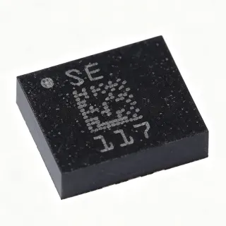
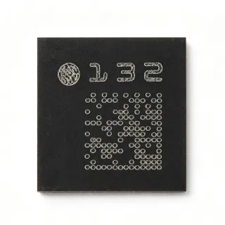
MMA8452QR1 - 3-Axis 12-bit Digital Accelerometer I2C | NXP | QFN-16
MPN: MMA8452QR1 ✗ End of Life| Qty | Unit Price | Extended |
|---|---|---|
| 1 | $3.95 | $3.95 |
| 10 | $3.55 | $35.50 |
| 100 | $3.1 | $310.00 |
| 500 | $2.75 | $1,375.00 |
| 1,000 | $2.4 | $2,400.00 |
MMA8452QR1 Overview
An accelerometer is a micro-electro-mechanical (MEMS) sensor that measures proper acceleration along one or more axes, converting mechanical motion into an electrical signal proportional to g-force. The MMA8452QR1 belongs to the accelerometer -> inertial sensor -> MEMS device -> semiconductor taxonomy, sitting at the lowest physical layer of any motion-aware electronic system. It provides the raw motion data that microcontrollers or DSPs translate into orientation, gesture, vibration, or step-count information.
Key features include configurable embedded interrupt functions that relieve the host processor from continuous polling, two programmable interrupt pins (INT1, INT2), an orientation/portrait-landscape detection engine, a free-fall engine, a motion/free-fall/inactivity engine, and a pulse detection engine. The device also supports a transient detection engine with high-pass filter capability and FIFO buffer for power-efficient event capture.
Technically, the MMA8452QR1 uses a MEMS capacitive sensing element coupled to a low-noise CMOS ASIC with on-chip signal conditioning, temperature compensation, and a 12-bit successive-approximation ADC. Internal pull-ups on SDA/SCL (via VDDIO) reduce external BOM, and the device supports both 2-byte and single-byte I2C reads, enabling efficient register access.
Typical applications include cell phones and tablets (screen rotation, gaming), e-readers (page-turn detection), portable medical devices (fall detection, activity monitoring), smart remote controls, asset trackers, and industrial vibration monitoring platforms. The wide operating temperature range of -40C to +85C and low 6 uA standby current make it equally at home in handheld consumer and rugged industrial enclosures.
When designing with this part, observe the I2C bus pull-up sizing carefully because the internal pull-ups may need to be supplemented by external resistors for reliable operation above 400 kHz. The exposed pad on the QFN-16 must be soldered to the ground plane for thermal and electrical performance, and an external 0.1 uF bypass capacitor placed within 5 mm of the VDD pin is recommended.
This page synthesizes distributor pricing, drop-in alternative analysis (including the NXP-recommended FXLS family), and practical design notes not found in the manufacturer datasheet alone.
Drop-in alternatives for MMA8452QR1 — same package, pin-to-pin compatible. Different-package parts requiring PCB rework are excluded.
Variants in this series
Same-series models that are drop-in compatible with MMA8452QR1 (same form factor and footprint) — differing in Operating Temperature, Package, Supply Voltage (VDD).
Quick Comparison Tool — Select alternative parts for side-by-side comparison:
MMA8452QT
✅ Drop-In📋 Reference alternative (not in catalog)
MMA8451QR1
✅ Drop-In📋 Reference alternative (not in catalog)
MMA8453QR1
✅ Drop-In📋 Reference alternative (not in catalog)
MMA7455LR1
✅ Drop-In📋 Reference alternative (not in catalog)
FXLS8962AF
✅ Drop-In📋 Reference alternative (not in catalog)
MMA8452QR1 Maximum Ratings & Electrical Characteristics
| Sensor Type | 3-Axis Capacitive MEMS Accelerometer |
| Resolution | 12-bit / 8-bit selectable |
| Full-Scale Range | ±2g / ±4g / ±8g (user selectable) |
| Output Interface | I2C (up to 400 kHz) |
| Supply Voltage (VDD) | 1.91 V to 3.6 V |
| Supply Voltage (VDDIO) | 1.62 V to 3.6 V |
| Output Data Rate (ODR) | 0.78 Hz to 400 Hz |
| Standby Current | 6 uA typical |
| Interrupt Pins | 2 (INT1, INT2, programmable) |
| Operating Temperature | -40 C to +85 C |
| Package | 16-QFN (3x3 mm) with exposed pad |
| Mounting Type | Surface Mount |
| Axes Measured | X, Y, Z |
| Embedded Functions | Orientation, Free-fall, Motion, Transient, Pulse, FIFO |
| MSL Level | MSL1 per JEDEC J-STD-020 |
| I2C Address | 0x1D / 0x1C (configurable SA0 pin) |
MMA8452QR1 Pin Configuration
| Pin 1 | VDD — Main power supply, 1.91 V to 3.6 V (decoupling cap to pin) |
| Pin 2 | VDDIO — I/O supply, 1.62 V to 3.6 V |
| Pin 3 | RESV — Reserved pin - leave floating or tie to GND per datasheet |
| Pin 4 | GND — Ground return for digital and analog blocks |
| Pin 5 | SCL — I2C clock input (internal pull-up to VDDIO) |
| Pin 6 | SDA — I2C data (internal pull-up to VDDIO) |
| Pin 7 | SA0 — I2C slave address LSB select (0x1C/0x1D) |
| Pin 8 | RESV — Reserved - leave floating or tie to GND per datasheet |
| Pin 9 | INT1 — Programmable interrupt 1, active high |
| Pin 10 | INT2 — Programmable interrupt 2, active high |
| Pin 11 | RESV — Reserved - leave floating or tie to GND per datasheet |
| Pin 12 | RESV — Reserved - leave floating or tie to GND per datasheet |
| Pin 13 | GND — Ground reference |
| Pin 14 | RESV — Reserved - leave floating or tie to GND per datasheet |
| Pin 15 | RESV — Reserved - leave floating or tie to GND per datasheet |
| Pin 16 | EPAD — Exposed pad - solder to PCB ground plane for thermal and electrical performance |
Typical Applications
MMA8452QR1 is suitable for 6 applications: Smartphone Screen Rotation, Wearable Fitness Tracker / Pedometer, Tablet Tilt and Tap-to-Wake Detection, Industrial Asset Tracker Vibration Monitor, Free-Fall Detection in Portable HDD / SSD, Pedestrian Dead Reckoning / Indoor Navigation.
Smartphone Screen Rotation
The MMA8452QR1 provides portrait-landscape orientation detection at a ±2g full scale, allowing a smartphone to rotate its display in real time. Its embedded orientation engine and pulse-detection block interrupt the host only when a valid orientation transition is qualified, keeping the application processor in low-power sleep during idle. With 6 uA standby current and ODR up to 400 Hz, the sensor responds to user tilts within ~2.5 ms while adding negligible battery drain to a phone platform. The 3x3 mm QFN-16 footprint saves board area next to the PMIC, and the 1.91V to 3.6V supply pairs directly with a Li-ion cell after regulation. Designers can also enable the high-pass filter to ignore slow gravity drift.
Recommended
Wearable Fitness Tracker / Pedometer
In a wearable wristband, the MMA8452QR1 detects step count, wrist-flick gesture, and inactivity using its embedded motion and pulse engines. The 6 uA standby and the 32-sample FIFO buffer let the MCU stay asleep while buffering samples, extending battery life on coin-cell platforms. Built-in high-pass filters reject DC gravity drift, so walking-step transitions are detected cleanly even with the wrist rotating at various angles. The 1.91V to 3.6V supply matches a single Li-ion or Li-polymer cell, and the 16-QFN (3x3 mm) package fits inside compact 25 mm x 30 mm wearable housings. Combined with its -40C to +85C range, the MMA8452QR1 survives outdoor winter activity and tropical-day heat without recalibration.
Recommended
Tablet Tilt and Tap-to-Wake Detection
The MMA8452QR1 supports tap and double-tap recognition through its embedded pulse-detection engine, enabling tap-to-wake and click-pad interactions on tablets and 2-in-1 laptops. Its 12-bit data and programmable threshold windows let designers tune sensitivity to the screen-bezel mass, avoiding false taps from accidental hand rests. With the FIFO and high-pass filtering, the host CPU wakes only on validated events, drawing 6 uA standby current during idle UI states. The I2C interface (up to 400 kHz) keeps the pin count low across multiple sensors, and the ±2g / ±4g / ±8g selection lets engineers dynamically scale resolution to match tilt vs. impact events. The NXP-recommended FXLS8962AF migration path keeps the same QFN-16 footprint for next-gen designs.
Recommended
Industrial Asset Tracker Vibration Monitor
The MMA8452QR1 monitors vibration signatures on industrial pumps, motors, and conveyor components when paired with a low-power cellular or LoRa MCU. Its wide operating temperature range of -40C to +85C and 400 Hz max ODR (12-bit resolution) capture enough spectral detail for FFT-based vibration analysis at low sampling rates. The 32-sample FIFO allows the asset tracker to record only meaningful vibration events and transmit compressed buffers, saving metered cellular uplink bandwidth. Two interrupt pins drive wake-up events directly, freeing the MCU from continuous polling loops. The exposed-pad QFN-16 allows direct PCB copper heatsinking, important when the sensor sits next to a relay coil or solenoid driver. Engineers can migrate to FXLS8962AF for new industrial designs needing ±16g events.
Recommended
Free-Fall Detection in Portable HDD / SSD
The MMA8452QR1's free-fall engine detects the sudden loss of gravity when a portable storage device is dropped, triggering an immediate park-head command to prevent hard-drive platter damage. Detection threshold and integration time are register-programmable via I2C, and the INT1 pin can be wired directly to the storage controller's GPIRQ without MCU intervention, saving critical milliseconds in a drop event. With ±2g / ±4g / ±8g selectable range, the threshold can be tuned to typical 0.5g drop signatures while ignoring normal usage shocks. The 6 uA standby current makes it suitable for battery-powered external SSDs and ruggedized portable drives where every milliamp-hour matters. Pin-to-pin replacement by FXLS8962AF is recommended for new designs, with form factor compatibility on QFN-16.
Recommended
Pedestrian Dead Reckoning / Indoor Navigation
The MMA8452QR1 supports pedestrian dead reckoning (PDR) and indoor navigation systems by detecting step and stride events in conjunction with a magnetometer or gyroscope. Its ±8g full scale captures the impact spikes of heel strikes during walking, and its motion engine can be configured to deliver step counts at up to 400 Hz ODR. The FIFO buffer lets the host MCU integrate samples before computing stride length, optimizing system power. Low 6 uA standby current and I2C interface compatibility across the NXP FXOS8700 magnetometer family make this sensor a natural fit for personal navigation units. Per NXP Community guidance, the FXLS8962AF or FXLS8964 should be adopted in new PDR designs requiring ±16g impact handling.
Recommended
Recommended Products Summary
Engineering reference data for MMA8452QR1 — comparison, design guidance, and compliance information.
Selection Guide
Comparison with Alternatives
| Parameter | This Product | MMA8452QT | MMA8451QR1 | MMA8453QR1 | MMA7455LR1 | FXLS8962AF |
|---|---|---|---|---|---|---|
| Package | 16-QFN (3x3 mm) | 16-QFN (3x3 mm) - same | 16-QFN (3x3 mm) - same | 16-QFN (3x3 mm) - same | 16-QFN (3x3 mm) - same | 16-QFN (3x3 mm) - same |
| Brand | NXP Semiconductors | NXP Semiconductors | NXP Semiconductors | NXP Semiconductors | NXP Semiconductors | NXP Semiconductors |
| Resolution | 12-bit / 8-bit selectable | 12-bit / 8-bit selectable - same | 14-bit | 10-bit / 8-bit | 8-bit | 12-bit |
| Full-Scale Range | ±2g / ±4g / ±8g | ±2g / ±4g / ±8g - same | ±2g / ±4g / ±8g | ±2g / ±4g / ±8g | ±2g / ±4g / ±8g | ±2g / ±4g / ±8g / ±16g |
| Interface | I2C up to 400 kHz | I2C - same | I2C | I2C | I2C / SPI | I2C / SPI |
| Supply Voltage | 1.91 V to 3.6 V | 1.91 V to 3.6 V | 1.95 V to 3.6 V | 1.91 V to 3.6 V | 2.4 V to 3.6 V | 1.71 V to 3.6 V |
| Output Data Rate | 0.78 Hz to 400 Hz | 0.78 Hz to 400 Hz - same | 0.78 Hz to 400 Hz | 0.78 Hz to 400 Hz | 62.5 Hz to 125 Hz | 0.78 Hz to 6.66 kHz |
| Embedded Functions | Orientation, Free-fall, Motion, Transient, Pulse, FIFO (32 sample) | Same - identical silicon | Same plus 14-bit data path | Simplified function set | Minimal legacy feature set | Modern engine set plus temperature comp |
| AEC-Q100 Qualified | No (industrial) | No | No | No | No | Yes |
Key Differentiators
- Broadest embedded-function set in a QFN-16 3-axis accelerometer (vs MMA8453QR1)
- Lower power than the legacy MMA7455 series (vs MMA7455LR1)
- Lower-cost 12-bit upgrade path to the FXLS family (vs FXLS8962AF)
- Higher-resolution alternate in the same footprint (vs MMA8451QR1)
Design Notes
Place a 0.1 uF X7R decoupling capacitor within 5 mm of the VDD pin and a separate 0.1 uF on the VDDIO pin. The internal I2C pull-ups on SDA/SCL draw current proportional to bus frequency - for sustained 400 kHz operation above 3 V VDDIO, supplement with external 4.7 kohm resistors to ensure rise-time compliance. Power-on sequence: VDD should reach 90 percent of nominal before VDDIO exceeds 1.62 V to prevent I/O latch-up, per NXP datasheet application notes.
The 16-QFN (3x3 mm) exposed pad is the primary thermal path. Solder the EPAD to a continuous ground copper pour of at least 100 mm^2 to keep theta_JA below 150 C/W. In handheld enclosures reaching +45 C ambient during solar exposure, the sensor self-heating is below 1 C so thermal errors are negligible, but in sealed industrial cabinets at +85 C ambient the sensor output may drift and re-calibration per the NXP datasheet is recommended.
Route I2C traces as short as possible to the MCU, keeping them matched-length and away from switching regulators or noisy clock traces. Place the sensor on a separate inner PCB layer if the board has a noisy cellular or motor driver subsystem, with vias stitching the ground around the sensor. The 3x3 mm footprint requires no clearance on the top layer if the EPAD is designed per JEDEC JESD51-7; the recommended land pattern is in the NXP application note section.
Do not float SA0 at system boot - tie it firmly to VDDIO or GND. A floating SA0 leaves the I2C address indeterminate and can cause the MCU to miss events after power cycling. Avoid hot-plugging I2C pull-ups when VDDIO is unpowered, which can back-drive the sensor. If using interrupts INT1/INT2, route them away from the I2C bus to avoid capacitive coupling on the 100 kHz edges. For free-fall detection, set the threshold below 0.5g and the debounce timer to at least 30 ms to avoid false triggers during normal shake events.
Compliance Information
RoHS compliant per NXP product page; however, part is obsolete per NXP Community EOL communication and last-time-buy windows have closed. New designs should migrate to FXLS8962AF for AEC-Q100 qualification.