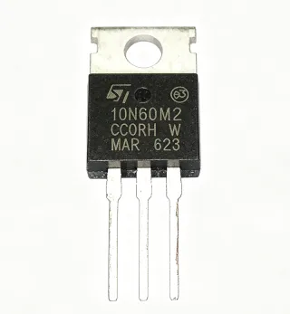
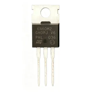
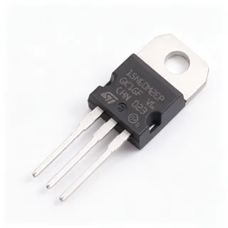
STP16NF06L - 16A, 60V N-Channel Power MOSFET | STMicroelectronics
MPN: STP16NF06L ✓ Active| Qty | Unit Price | Extended |
|---|---|---|
| 1 | $0.85 | $0.85 |
| 10 | $0.76 | $7.60 |
| 100 | $0.68 | $68.00 |
| 500 | $0.61 | $305.00 |
| 1,000 | $0.55 | $550.00 |
STP16NF06L Overview
A Power MOSFET is a type of field-effect transistor optimized for switching and amplification of power. It operates by controlling the conductivity between the drain and source terminals through an insulated gate voltage. Power MOSFETs are fundamental building blocks in power electronics, serving as switches in DC-DC converters, motor drivers, and power supplies. They are part of the broader category of discrete semiconductors, which also includes diodes, thyristors, and IGBTs. The STP16NF06L is specifically an enhancement-mode N-channel device, meaning it requires a positive gate-to-source voltage to conduct.
Key features of the STP16NF06L include a low threshold voltage (VGS(th)) of 1V to 2V, making it suitable for logic-level drive, and a fast switching speed with typical rise and fall times of 40ns and 25ns, respectively. The device also offers a high avalanche energy rating, ensuring robustness in inductive load switching. Its low RDS(on) minimizes conduction losses, improving overall system efficiency.
The STP16NF06L is built using STMicroelectronics' advanced PowerMESH technology, which reduces on-state resistance and switching losses while maintaining high ruggedness. The device includes an intrinsic body diode with a reverse recovery time of 60ns, which is beneficial for freewheeling current in inductive loads. The TO-220 package provides a thermal resistance of 62.5°C/W (junction-to-ambient) and 3.33°C/W (junction-to-case), allowing for effective heat dissipation with appropriate heatsinking.
Typical applications include DC-DC converters, motor control circuits, power supplies, and load switching. In a DC-DC buck converter, the STP16NF06L can switch at frequencies up to 100kHz, providing efficient power conversion. In motor control, its low RDS(on) and fast switching reduce power loss and improve motor performance. The device is also suitable for battery management systems and automotive applications, though it is not AEC-Q100 qualified.
When designing with the STP16NF06L, ensure adequate gate drive voltage (at least 10V for full enhancement) and proper heatsinking for high-current operation. The gate-source voltage must not exceed ±20V to prevent oxide breakdown. For high-frequency switching, use a gate resistor to control switching speed and reduce EMI.
Drop-in alternatives for STP16NF06L — same package, pin-to-pin compatible. Different-package parts requiring PCB rework are excluded.
Quick Comparison Tool — Select alternative parts for side-by-side comparison:
STP16NF06
✅ Drop-In ⚠️ Specs Unverified📋 Reference alternative (not in catalog)
IRFZ44N
✅ Drop-In ⚠️ Specs Unverified📋 Reference alternative (not in catalog)
IRLB3034PBF
✅ Drop-In ⚠️ Specs Unverified📋 Reference alternative (not in catalog)
FDP16AN08A0
✅ Drop-In ⚠️ Specs Unverified📋 Reference alternative (not in catalog)
STP16NF06L Maximum Ratings & Electrical Characteristics
| Drain-to-Source Voltage (VDS) | 60 V |
| Continuous Drain Current (ID) at 25°C | 16 A |
| Continuous Drain Current (ID) at 100°C | 11 A |
| Pulsed Drain Current (IDM) | 64 A |
| Gate-to-Source Voltage (VGS) | ±20 V |
| On-State Resistance (RDS(on)) at VGS=10V | 0.09 ohm (typ), 0.12 ohm (max) |
| Threshold Voltage (VGS(th)) | 1 V to 2 V |
| Power Dissipation (PD) at 25°C | 45 W |
| Operating Junction Temperature | -55°C to +175°C |
| Package | TO-220 |
| Mounting Type | Through Hole |
| Thermal Resistance (Junction-to-Case) | 3.33 °C/W |
| Thermal Resistance, Junction-to-Ambient | 62.5 °C/W |
| Gate Charge (Qg) at VGS=10V | 20 nC (typ) |
| Reverse Recovery Time (trr) | 60 ns |
| RoHS Status | Compliant |
STP16NF06L Pin Configuration
| Pin 1 | Gate — Gate terminal for controlling the MOSFET |
| Pin 2 | Drain — Drain terminal, connected to the load |
| Pin 3 | Source — Source terminal, connected to ground |
Safe Operating Area
Typical Applications
STP16NF06L is suitable for 6 applications: DC-DC Converters, Motor Control, Power Supplies, Load Switching, Battery Management, Automotive (Non-Qualified).
DC-DC Converters
The STP16NF06L is used as a switching element in buck, boost, and buck-boost converters. Its low RDS(on) of 0.09 ohm minimizes conduction losses, and its fast switching speed (rise/fall times of 40/25ns) enables high-frequency operation up to 100kHz. In a typical buck converter, the MOSFET switches at a duty cycle determined by the output voltage, with the body diode providing freewheeling during dead time. The low gate charge of 20nC reduces driver power requirements, making it suitable for battery-powered applications. For a 12V to 5V conversion at 5A, the conduction loss is approximately 2.25W (I^2*R), which is manageable with a heatsink. The device's 60V VDS rating provides ample margin for input voltage transients.
Recommended
Motor Control
In motor control circuits, the STP16NF06L is used in H-bridge or half-bridge configurations to drive DC motors or stepper motors. Its 16A continuous current rating and 64A pulsed current capability handle inrush currents during motor startup. The fast body diode reverse recovery time of 60ns reduces switching losses during freewheeling. The low threshold voltage allows direct interfacing with microcontrollers or gate drivers. For a 24V DC motor drawing 10A, the conduction loss is about 9W (I^2*R), requiring a heatsink. The device's ruggedness against avalanche ensures reliability when switching inductive loads. PWM frequency can be up to 20kHz for silent operation, and the MOSFET's fast switching minimizes EMI when proper gate resistors are used.
Recommended
Power Supplies
The STP16NF06L is employed in switch-mode power supplies (SMPS) for AC-DC and DC-DC conversion. Its 60V VDS rating is suitable for offline flyback converters with a 12V output. The low RDS(on) reduces conduction losses, improving efficiency. The device's fast switching speed allows operation at frequencies up to 100kHz, reducing transformer size. In a typical flyback converter, the MOSFET switches the primary side of the transformer, with the body diode clamping voltage spikes. The gate charge of 20nC simplifies gate drive design. For a 100W power supply, the MOSFET dissipates about 5W, requiring a heatsink. The device's thermal resistance of 3.33°C/W (junction-to-case) allows effective heat transfer to a heatsink.
Recommended
Load Switching
The STP16NF06L is used as a high-side or low-side load switch to control power to various loads such as relays, lamps, and solenoids. Its low threshold voltage allows direct control from a microcontroller's GPIO pin. The 16A current rating can handle most loads, and the low RDS(on) minimizes voltage drop across the switch. For a 12V load drawing 5A, the voltage drop is only 0.45V (I*R), ensuring efficient power delivery. The device's fast switching speed enables PWM dimming of lamps or speed control of fans. The TO-220 package with a heatsink tab allows for easy mounting on a PCB or chassis. The device's robustness against short circuits and overcurrent conditions makes it reliable for load switching applications.
Recommended
Battery Management
In battery management systems (BMS), the STP16NF06L is used for cell balancing, protection, and charge/discharge control. Its low RDS(on) minimizes power loss during high-current charging and discharging. The 60V VDS rating is suitable for battery packs up to 48V. The device's fast switching speed enables efficient PWM control for cell balancing. The low threshold voltage allows direct interfacing with battery monitoring ICs. For a 48V battery pack with 20A discharge current, the conduction loss is about 36W (I^2*R), requiring a heatsink. The device's avalanche ruggedness ensures reliability during fault conditions. The TO-220 package is suitable for PCB mounting with a heatsink.
Recommended
Automotive (Non-Qualified)
Although not AEC-Q100 qualified, the STP16NF06L can be used in non-safety-critical automotive applications such as interior lighting, seat heaters, and infotainment systems. Its 60V VDS rating handles 12V and 24V automotive electrical systems. The low RDS(on) reduces heat generation, and the wide operating temperature range (-55°C to +175°C) suits harsh environments. The device's fast switching speed enables PWM dimming of LED lights. For a 12V LED strip drawing 5A, the conduction loss is about 2.25W, manageable with a small heatsink. The TO-220 package is robust for automotive vibration. However, for safety-critical applications, use AEC-Q101 qualified MOSFETs.
Recommended
Recommended Products Summary
Engineering reference data for STP16NF06L — comparison, design guidance, and compliance information.
Selection Guide
Comparison with Alternatives
| Parameter | This Product | STP16NF06 | IRFZ44N | IRLB3034PBF | FDP16AN08A0 |
|---|---|---|---|---|---|
| Package | TO-220 | TO-220 | TO-220 | TO-220 | TO-220 |
| Brand | STMicroelectronics | STMicroelectronics | Infineon | Infineon | onsemi |
| Drain-to-Source Voltage (VDS) | 60 V | 60 V | 55 V | 40 V | 75 V |
| Continuous Drain Current (ID) at 25°C | 16 A | 16 A | 49 A | 195 A | 16 A |
| On-State Resistance (RDS(on)) at VGS=10V | 0.09 ohm (typ) | 0.09 ohm (typ) | 0.0175 ohm (typ) | 0.0014 ohm (typ) | 0.008 ohm (typ) |
| Gate Threshold Voltage (VGS(th)) | 1 V to 2 V | 2 V to 4 V | 2 V to 4 V | 1 V to 2 V | 2 V to 4 V |
| Power Dissipation (PD) at 25°C | 45 W | 45 W | 94 W | 200 W | 45 W |
| Gate Charge (Qg) | 20 nC (typ) | 20 nC (typ) | 63 nC (typ) | 110 nC (typ) | 20 nC (typ) |
Key Differentiators
- Logic-level gate threshold (1-2V) (vs STP16NF06)
- Lower RDS(on) than some alternatives (vs FDP16AN08A0)
- Cost-effective for moderate power (vs IRFZ44N)
Design Notes
The STP16NF06L has a junction-to-case thermal resistance of 3.33°C/W and a maximum power dissipation of 45W at 25°C case temperature. For high-current applications, calculate the power dissipation (P = I^2 * RDS(on)) and ensure the junction temperature stays below 175°C. For example, at 16A and RDS(on)=0.09 ohm, P = 23W, resulting in a junction-to-case temperature rise of 76.6°C. Use a heatsink with adequate thermal resistance to keep the case temperature low. The TO-220 package has a metal tab that can be mounted to a heatsink with thermal compound.
For the TO-220 package, ensure the leads are properly soldered to the PCB with sufficient copper area for heat dissipation. The drain tab is electrically connected to the drain, so if using a heatsink, ensure proper electrical isolation (e.g., mica washer and insulating bushing) to avoid short circuits. Place gate drive components (resistor, zener) close to the gate pin to minimize loop area and reduce EMI. Use a gate resistor of 10-100 ohm to control switching speed and reduce ringing.
Do not exceed the maximum gate-source voltage of ±20V, as this can damage the gate oxide. In high dV/dt applications, use a gate protection zener diode (e.g., 15V) to clamp voltage spikes. Ensure the gate drive voltage is at least 10V to achieve the specified low RDS(on). If driving with a microcontroller at 3.3V or 5V, the MOSFET will still switch but with higher on-resistance, increasing power loss. Also, consider the body diode's reverse recovery time (60ns) in high-frequency switching to avoid excessive losses.
Compliance Information
RoHS compliant per STMicroelectronics product page. Not AEC-Q100 qualified; for automotive use, consider AEC-Q101 qualified devices.