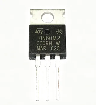
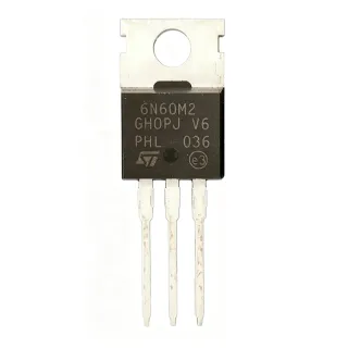
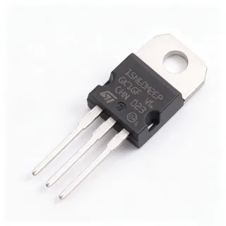
STP4N60 - 600V 4A N-Channel Power MOSFET | STMicroelectronics
MPN: STP4N60 ✓ Active| Qty | Unit Price | Extended |
|---|---|---|
| 1 | $0.85 | $0.85 |
| 10 | $0.76 | $7.60 |
| 100 | $0.68 | $68.00 |
| 500 | $0.61 | $305.00 |
| 1,000 | $0.55 | $550.00 |
STP4N60 Overview
A Power MOSFET is a type of field-effect transistor optimized for high-power switching and amplification. It operates by controlling the flow of current between the drain and source terminals through an electric field applied at the gate. Power MOSFETs are widely used in power electronics due to their fast switching speeds, high input impedance, and low on-state resistance, making them ideal for applications such as switch-mode power supplies (SMPS), DC-DC converters, and motor drivers. They are a key component in the broader category of discrete semiconductors, which also includes diodes, thyristors, and IGBTs.
Key features of the STP4N60 include a low on-resistance (RDS(on)) of typically 2.5 ohm at VGS=10V, a gate charge (Qg) of 20 nC, and a fast switching time. The device is designed to handle high voltage and current with a maximum power dissipation of 70W at 25°C case temperature. It also features an integrated gate-source ESD protection, enhancing its robustness in harsh environments. The TO-220 package offers a thermal resistance of 62.5°C/W (junction-to-ambient) and 1.79°C/W (junction-to-case), allowing efficient heat dissipation when mounted on a heatsink.
The STP4N60 utilizes a planar stripe layout and advanced strip technology, which optimizes the trade-off between on-resistance and switching performance. This architecture ensures low conduction losses and reduced switching losses, making it suitable for high-frequency operation up to 100 kHz. The device is fully RoHS compliant and halogen-free, meeting modern environmental standards.
Typical applications include switch-mode power supplies (SMPS), power factor correction (PFC) circuits, electronic ballasts for lighting, and motor control in industrial and consumer equipment. Its high voltage rating and moderate current capability make it a versatile choice for offline power converters and auxiliary power supplies.
When designing with the STP4N60, ensure proper gate drive voltage (typically 10V) to achieve low on-resistance. A gate resistor may be needed to control switching speed and reduce EMI. Adequate heatsinking is essential for high-power applications to keep the junction temperature within safe limits.
Drop-in alternatives for STP4N60 — same package, pin-to-pin compatible. Different-package parts requiring PCB rework are excluded.
Quick Comparison Tool — Select alternative parts for side-by-side comparison:
STP4N60FP
✅ Drop-In📋 Reference alternative (not in catalog)
STP4N60FI
✅ Drop-In ⚠️ Specs Unverified📋 Reference alternative (not in catalog)
IRF840
✅ Drop-In ⚠️ Specs Unverified📋 Reference alternative (not in catalog)
FQPF4N60
✅ Drop-In ⚠️ Specs Unverified📋 Reference alternative (not in catalog)
STP4N60M2
✅ Drop-In ⚠️ Specs Unverified📋 Reference alternative (not in catalog)
STP4N60 Maximum Ratings & Electrical Characteristics
| Polarity | N-Channel |
| Drain-Source Breakdown Voltage (V(BR)DSS) | 600 V |
| Continuous Drain Current (ID) at 25°C | 4 A |
| Continuous Drain Current (ID) at 100°C | 2.5 A |
| Pulsed Drain Current (IDM) | 16 A |
| Gate-Source Voltage (VGS) | ±30 V |
| On-Resistance (RDS(on)) at VGS=10V | 2.5 ohm (typ), 3.6 ohm (max) |
| Gate Charge (Qg) | 20 nC (typ) |
| Input Capacitance (Ciss) | 520 pF (typ) |
| Output Capacitance (Coss) | 80 pF (typ) |
| Reverse Transfer Capacitance (Crss) | 15 pF (typ) |
| Maximum Power Dissipation (PD) at 25°C | 70 W |
| Operating Temperature Range | -55°C to +150°C |
| Package | TO-220 |
| Mounting Type | Through Hole |
| RoHS Status | Compliant |
| Halogen Free | Yes |
STP4N60 Pin Configuration
| Pin 1 | Gate — Gate terminal for controlling the MOSFET |
| Pin 2 | Drain — Drain terminal, connected to the load |
| Pin 3 | Source — Source terminal, connected to ground |
Safe Operating Area
Typical Applications
STP4N60 is suitable for 6 applications: Switch-Mode Power Supplies (SMPS), Power Factor Correction (PFC) Circuits, Electronic Ballasts for Lighting, Motor Control, Auxiliary Power Supplies, DC-DC Converters.
Switch-Mode Power Supplies (SMPS)
The STP4N60 is ideal for SMPS due to its 600V breakdown voltage and 4A current capability. In a typical flyback converter, the MOSFET switches at high frequency (up to 100 kHz) to regulate output voltage. Its low on-resistance (2.5 ohm) minimizes conduction losses, improving efficiency. The TO-220 package allows easy heatsinking for dissipating heat generated during switching. Compared to bipolar transistors, the MOSFET offers faster switching and simpler drive circuitry, making it a preferred choice for modern power supplies.
Recommended
Power Factor Correction (PFC) Circuits
In PFC circuits, the STP4N60 is used as a boost switch to shape the input current waveform, improving power factor. Its high voltage rating (600V) handles the boosted DC bus voltage (typically 400V). The fast switching speed and low gate charge (20 nC) enable high-frequency operation, reducing the size of magnetic components. The device's robustness ensures reliable operation in continuous conduction mode (CCM) or critical conduction mode (CrM) PFC stages.
Recommended
Electronic Ballasts for Lighting
The STP4N60 is used in electronic ballasts for fluorescent and HID lamps. It operates as a switching element in the inverter stage, converting DC to high-frequency AC to drive the lamp. Its 600V rating is sufficient for the high-voltage spikes in the resonant tank. The low on-resistance reduces power loss, and the TO-220 package facilitates thermal management. The device's fast switching ensures efficient operation at frequencies above 20 kHz, eliminating audible noise.
Recommended
Motor Control
In motor control applications, the STP4N60 is used in low-power motor drives, such as those in fans, pumps, and small appliances. It can be used in the inverter stage of a variable frequency drive (VFD) to control the motor speed. The 600V rating allows operation from rectified mains voltage (up to 340V DC). The device's fast switching and low gate charge enable PWM control at frequencies up to 20 kHz, reducing acoustic noise. Proper gate drive and snubber circuits are recommended to handle inductive loads.
Recommended
Auxiliary Power Supplies
The STP4N60 is suitable for auxiliary power supplies in industrial and consumer equipment, providing isolated DC rails for control circuits. Its 600V rating allows direct connection to the rectified mains, simplifying the design. The low on-resistance ensures high efficiency, and the TO-220 package is easy to mount on a PCB with a heatsink. The device's robustness against voltage spikes makes it reliable in harsh environments.
Recommended
DC-DC Converters
In DC-DC converters, the STP4N60 can be used in high-voltage input applications, such as telecom and industrial power systems. It operates as a switch in buck, boost, or flyback topologies. The 600V rating is suitable for input voltages up to 400V. The low gate charge and fast switching reduce switching losses, enabling high-frequency operation and smaller magnetics. The device's thermal performance is adequate for moderate power levels with proper heatsinking.
Recommended
Recommended Products Summary
Engineering reference data for STP4N60 — comparison, design guidance, and compliance information.
Selection Guide
Comparison with Alternatives
| Parameter | This Product | STP4N60FP | IRF840 | FQPF4N60 |
|---|---|---|---|---|
| Package | TO-220 | TO-220 (full-pack) | TO-220 | TO-220 |
| Brand | STMicroelectronics | STMicroelectronics | Vishay | onsemi |
| Drain-Source Breakdown Voltage | 600 V | 600 V | 500 V | 600 V |
| Continuous Drain Current (25°C) | 4 A | 4 A | 8 A | 4 A |
| On-Resistance (RDS(on)) | 2.5 ohm (typ) | 2.5 ohm (typ) | 0.85 ohm (typ) | 2.5 ohm (typ) |
| Gate Charge (Qg) | 20 nC | 20 nC | 63 nC | 20 nC |
| Maximum Power Dissipation | 70 W | 70 W | 125 W | 70 W |
| Operating Temperature Range | -55°C to +150°C | -55°C to +150°C | -55°C to +150°C | -55°C to +150°C |
Key Differentiators
- Higher voltage rating than IRF840 (vs IRF840)
- Lower gate charge than IRF840 (vs IRF840)
- Full-pack version available (vs FQPF4N60)
Design Notes
The STP4N60 has a maximum power dissipation of 70W at 25°C case temperature. In high-power applications, ensure adequate heatsinking to keep the junction temperature below 150°C. Use a thermal resistance of 1.79°C/W (junction-to-case) to calculate the required heatsink. For example, at 50W dissipation, the case temperature rise is 89.5°C, so a heatsink with a thermal resistance of less than 1.2°C/W is needed for 25°C ambient.
For TO-220 packages, ensure the mounting hole is properly sized and the tab is soldered to a large copper area for heat dissipation. Use a thermal pad or heatsink compound to improve thermal contact. Keep the gate drive traces short to minimize inductance and ringing. Place a gate resistor (e.g., 10 ohm) close to the gate to dampen oscillations.
Do not exceed the maximum gate-source voltage of ±30V. Use a zener diode or TVS for gate protection if the gate drive can spike. Ensure the drain-source voltage does not exceed 600V, especially during switching transients; use a snubber circuit if necessary. Also, avoid operating at high currents without proper heatsinking, as thermal runaway can occur.
Compliance Information
RoHS compliant and halogen-free per STMicroelectronics datasheet. Not AEC-Q100 qualified.