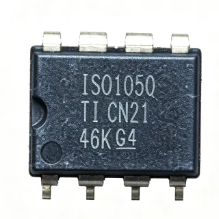
TJA1081GTS/0Z - FlexRay Node Transceiver Clamp 30 | NXP
MPN: TJA1081GTS/0Z ✓ Active| Qty | Unit Price | Extended |
|---|---|---|
| 1 | $0 | $0.00 |
| 10 | $0 | $0.00 |
| 100 | $0 | $0.00 |
| 500 | $0 | $0.00 |
| 1,000 | $0 | $0.00 |
TJA1081GTS/0Z Overview
A FlexRay transceiver is a physical-layer interface IC that converts the digital protocol signals of a FlexRay communication controller into the differential bus signals defined by the FlexRay electrical physical layer. In the vehicle networking hierarchy, it sits between the protocol controller (host MCU) and the twisted-pair FlexRay bus, forming part of the broader family of automotive network transceivers that also includes CAN, LIN and Ethernet PHY devices. FlexRay delivers deterministic, fault-tolerant, high-bandwidth communication for safety-critical and x-by-wire systems.
Key features include full compliance with ISO 17458-4:2013, dual-channel differential bus drivers and receivers, and enhanced low-power modes that are optimized for ECUs permanently connected to the battery. The Clamp 30 variant is specifically intended for nodes that remain powered from the car battery at all times, integrating protection behavior suited to always-battery-connected applications.
Technically, the TJA1081G implements the Bus Driver and Bus Receiver functions of the FlexRay physical layer with integrated transmit data, receive data and enable interfaces to the protocol controller. Its advanced power-management modes reduce quiescent current in standby while allowing the node to wake on bus activity, an essential property for body and chassis ECUs that draw power from Clamp 30 (battery terminal 30) even when the vehicle is parked.
Typical applications include chassis control modules, adaptive suspension and x-by-wire domains, advanced driver assistance system (ADAS) gateways, and powertrain ECUs that require the deterministic 10 Mbit/s communication that FlexRay provides over CAN-based networks.
A key design consideration is supply architecture: because the Clamp 30 variant is optimized for battery-permanent connection, the designer must verify the VBAT and VCC sequencing and the wake-up pin handling against the OEM electrical requirements. Always follow the manufacturer datasheet external component recommendations for the bus pins.
This page synthesizes distributor availability data, family cross-references, and drop-in alternative analysis not consolidated in the manufacturer datasheet.
Drop-in alternatives for TJA1081GTS/0Z — same package, pin-to-pin compatible. Different-package parts requiring PCB rework are excluded.
Quick Comparison Tool — Select alternative parts for side-by-side comparison:
TJA1081TS,112
✅ Drop-In📋 Reference alternative (not in catalog)
TJA1081TS,118
✅ Drop-In📋 Reference alternative (not in catalog)
TJA1081BTS,118
✅ Drop-In📋 Reference alternative (not in catalog)
TJA1081GTS/0Z Specifications
| Product Type | FlexRay node transceiver (Clamp 30) |
| Interface Standard | FlexRay Electrical Physical Layer, ISO 17458-4:2013 |
| Data Rate | 2.5 Mbit/s to 10 Mbit/s |
| Clamp Type | Clamp 30 (permanently battery-connected ECUs) |
| Bus Interface | Differential twisted-pair FlexRay bus (BM/BP) |
| Controller Interface | TXD, RXD protocol controller interface |
| Low Power Modes | Enhanced low-power modes, bus wake-up |
| Operating Temperature | -40C to +125C |
| Package | 16-SSOP |
| Mounting Type | Surface Mount |
TJA1081GTS/0Z 16-ssop Pin Configuration Guide
Pin configuration for TJA1081GTS/0Z (16-ssop package). Pin numbering, functions, and connection diagrams are defined in the manufacturer datasheet. Refer to it for the exact footprint and soldering guidelines.

No detailed pinout data available for TJA1081GTS/0Z.
Refer to the datasheet for full pin configuration.
Typical Applications
TJA1081GTS/0Z is suitable for 6 applications: Chassis Control Modules, ADAS Gateways and Domains, X-by-Wire Systems, Powertrain ECUs, Body Control and Gateway Modules, Instrument Cluster and Display Networks.
Chassis Control Modules
The TJA1081GTS/0Z fits chassis control ECUs such as adaptive suspension and active stabilizer modules, which rely on FlexRay's deterministic 10 Mbit/s communication to close control loops with cycle times that CAN cannot guarantee. As a Clamp 30 transceiver compliant with ISO 17458-4:2013, it connects the chassis protocol controller directly to the twisted-pair FlexRay bus while tolerating the -40C to +125C ambient range of underbody mounting locations. Its permanently-battery-connected optimization means the node retains bus wake-up capability in parked vehicles while drawing minimal standby current from terminal 30. Designers should follow the NXP datasheet bus termination and common-mode choke recommendations to meet the OEM EMC profile for chassis networks.
Recommended
ADAS Gateways and Domains
Advanced driver assistance gateways aggregate radar, camera and lidar data over FlexRay or a FlexRay backbone because the protocol provides time-triggered, fault-tolerant framing with bounded latency. The TJA1081GTS/0Z provides the physical layer for such gateways at 2.5 to 10 Mbit/s, interfacing the gateway microcontroller's FlexRay protocol controller to the differential bus with the signal quality required by ISO 17458-4:2013. The Clamp 30 configuration suits ADAS domains that must remain wake-capable while the ignition is off, supporting remote diagnostic and pre-conditioning wake scenarios. Integrated enhanced low-power modes reduce quiescent drain, which matters because ADAS modules are often continuously powered from the battery; bus wake-up then restores full-speed operation on detected bus activity.
Recommended
X-by-Wire Systems
Steer-by-wire and brake-by-wire architectures require redundancy and determinism that FlexRay was designed to deliver; the physical layer transceiver is a safety-relevant element of that chain. The TJA1081GTS/0Z implements the bus driver and receiver functions of ISO 17458-4:2013, delivering the differential signaling and symmetry that dual-channel redundant FlexRay topologies depend on at up to 10 Mbit/s. Its Clamp 30 supply optimization matches x-by-wire ECUs that remain battery-connected for continuous safety monitoring and diagnostic reporting even when the vehicle is off. With an ambient range of -40C to +125C, the transceiver supports the harsh locations typical of actuator control units, and designers should validate signal symmetry with the termination network specified in the NXP datasheet.
Recommended
Powertrain ECUs
Powertrain modules such as transmission and hybrid control units use FlexRay when engine, transmission and hybrid coordination demand synchronized, deterministic communication beyond CAN bandwidth. The TJA1081GTS/0Z supplies the bus interface at 2.5 to 10 Mbit/s with full ISO 17458-4:2013 compliance, and its -40C to +125C rating suits engine-bay placement near thermal loads. As a Clamp 30 device it aligns with powertrain ECUs that are wired directly to the battery to preserve diagnostic counters and immobilizer state across ignition cycles. Its enhanced low-power modes limit parked drain on terminal 30, addressing the OEM quiescent-current budgets that govern battery discharge over parking periods; full communication resumes on bus wake-up at the controller's configured 10 Mbit/s rate.
Recommended
Body Control and Gateway Modules
Body control modules and central gateways frequently bridge CAN/LIN subnetworks to a FlexRay backbone, and their transceivers must support battery-permanent connection with robust wake behavior. The TJA1081GTS/0Z provides exactly this profile: Clamp 30 optimization for always-battery-connected ECUs, enhanced low-power modes with bus wake-up, and ISO 17458-4:2013 physical layer compliance across 2.5 to 10 Mbit/s. Because body modules remain powered when parked, the transceiver's standby current behavior directly affects the vehicle's 12V battery discharge budget over multi-week parking. The 16-SSOP surface-mount package integrates into dense gateway PCBs alongside CAN and LIN transceivers, and the NXP datasheet application section details the external passive network required to meet automotive EMC immunity tests on the bus pins.
Recommended
Instrument Cluster and Display Networks
Premium instrument clusters and driver-information displays use FlexRay to receive time-correlated vehicle dynamics and safety data with bounded latency, ensuring gauge and warning content stays synchronized with the driving state. The TJA1081GTS/0Z terminates the cluster's FlexRay connection with ISO 17458-4:2013-compliant differential signaling at 2.5 to 10 Mbit/s. Its Clamp 30 wake behavior lets the cluster be woken over the FlexRay bus directly from the always-on battery rail, enabling features such as welcome animations and pre-ignition diagnostics without additional wake lines. Enhanced low-power modes then return the node to a low-current state after shutdown, and the -40C to +125C operating range accommodates windshield-adjacent thermal environments where cluster electronics are installed.
Recommended
Recommended Products Summary
Engineering reference data for TJA1081GTS/0Z — comparison, design guidance, and compliance information.
Selection Guide
Comparison with Alternatives
| Parameter | This Product | TJA1081TS,112 | TJA1081TS,118 | TJA1081BTS,118 |
|---|---|---|---|---|
| Package | 16-SSOP | SSOP-16 - same footprint | SSOP-16 - same footprint | SSOP-16 - same footprint |
| Brand | NXP Semiconductors | NXP Semiconductors | NXP Semiconductors | NXP Semiconductors |
| Interface Standard | FlexRay ISO 17458-4:2013 | FlexRay ISO 17458-4:2013 | FlexRay ISO 17458-4:2013 | FlexRay ISO 17458-4:2013 |
| Data Rate | 2.5-10 Mbit/s | 2.5-10 Mbit/s | 2.5-10 Mbit/s | 2.5-10 Mbit/s |
| Clamp Configuration | Clamp 30 (battery-permanent) | Standard clamp variant | Standard clamp variant | B-type clamp variant |
| Low-Power Modes | Enhanced low-power modes, bus wake-up | Family low-power modes | Family low-power modes | Family low-power modes (B variant config) |
| Typical Application | ECUs permanently connected to car battery | General FlexRay nodes | General FlexRay nodes | FlexRay nodes with B-type supply architecture |
Key Differentiators
- Clamp 30 optimization for battery-permanent ECUs (vs TJA1081TS,118)
- Full ISO 17458-4:2013 FlexRay compliance at 10 Mbit/s (vs TJA1081BTS,118)
- No verified cross-brand pin-compatible FlexRay equivalent exists (vs NXP TJA1081 family (all))
Design Notes
Follow the bus pin external network given in the NXP TJA1081 datasheet: the BP/BM differential pair requires the specified split termination and common-mode choke per the vehicle FlexRay physical layer design. Keep the transceiver close to the bus connector, route BP/BM as a matched-length differential pair (target 80 to 120 ohm differential impedance per OEM spec), and place decoupling capacitors on VBAT/VCC within a few millimeters of the pins. Do not route the TXD/RXD controller interface under the bus pair to avoid coupling switching transients into the logic lines.
Because the Clamp 30 variant is intended for ECUs permanently connected to the car battery, verify both load-dump and jump-start transients on the VBAT rail per the OEM electrical spec, and confirm the datasheet-recommended series protection (fuse or reverse-polarity element). Estimate standby budget: sum of TJA1081G standby current plus controller sleep current must stay within the OEM quiescent-current limit for the vehicle parking period; the enhanced low-power mode with bus wake-up exists precisely to satisfy these budgets.
Do not substitute TJA1081 family variants without confirming the clamp configuration: the TJA1081G (Clamp 30) targets battery-permanent ECUs, while TJA1081 and TJA1081B variants implement different clamp/wake behavior. A wrong clamp choice can break OEM wake-up requirements or draw excess current in park. Similarly, mismatched enable (EN) handling during controller reset can cause spurious bus frames; follow the datasheet power-up and reset sequencing guidance before asserting the bus driver.
Compliance Information
Compliance details not present in retrieved web data. The part is an automotive-grade NXP product and the datasheet URL is available; verify RoHS/REACH/AEC-Q100 status on the NXP product page at https://www.nxp.com/part/TJA1081GTS.