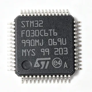
MC9S08DZ32ACLF - 32KB Flash 8-bit CAN MCU, 40MHz LQFP-48 | NXP
N.º da peça: MC9S08DZ32ACLF ✗ Fim de vida| Qtd. | Preço unitário | Total |
|---|---|---|
| 1 | $5.92 | $5,92 |
| 10 | $5.45 | $54,50 |
| 100 | $4.78 | $478,00 |
| 500 | $4.21 | $2.105,00 |
| 1.000 | $3.74 | $3.740,00 |
MC9S08DZ32ACLF Visão geral
An 8-bit microcontroller (MCU) is a single-chip computer that integrates a CPU, RAM, program memory (Flash), and peripheral interfaces (timers, ADC, communication ports) into one device. Within the broader hierarchy, the MC9S08DZ32ACLF belongs to the HCS08 sub-family of the S08 8-bit line, which itself falls under microcontrollers -> microprocessors and logic -> semiconductor ICs. The part is part of NXP's S08DZ series that combines CAN 2.0A/B, LIN, SCI, SPI and I2C peripherals with embedded Flash and EEPROM.
Key features include 32 KB of on-chip Flash program memory with in-application programming support, 2 KB of SRAM, on-chip EEPROM for data storage, a 24-channel 12-bit ADC with 2.5 µs conversion time, an analog comparator, and up to 32 interrupt sources. The integrated MSCAN (CAN 2.0 A/B) and LIN-master-capable SCI make it well suited for vehicle body and industrial sensor networks. Background debug mode (BGND) and on-chip emulation are available through the standard HCS08 debug interface.
Architecturally the part uses the enhanced HCS08 CPU core running at 40 MHz with a 20 MHz internal bus, retains the HC08 instruction set for code compatibility and adds the BGND instruction for debug. The integrated voltage regulator, low-power run/wait/stop modes, and a wide supply range (2.7 V to 5.5 V) support both 3.3 V and 5 V systems typical of automotive body controllers.
Typical applications include automotive body and chassis CAN/LIN nodes, industrial sensor and actuator modules, HVAC controllers, instrument cluster sub-modules, and general-purpose 8-bit embedded control with on-chip CAN. The combination of 32 KB Flash and 2 KB RAM is sufficient for typical CAN-stack plus application firmware.
When designing with the MC9S08DZ32ACLF, ensure that the IRQ, RESET and BKGD/MS pins are routed correctly for the chosen debug tool (P&E Multilink or equivalent). Decouple VDD/VSS pairs close to the package and follow NXP's reference layout for the 48-LQFP to avoid ESD and EMC issues on CAN bus pins.
This page synthesizes distributor pricing, drop-in alternatives and practical design notes not found in the manufacturer datasheet alone.
Alternativas drop-in para MC9S08DZ32ACLF — mesmo encapsulamento, compatível pino a pino. Peças de encapsulamento diferente que exigem retrabalho na PCB são excluídas.
Variantes desta série
Modelos da mesma série compatíveis como drop-in com MC9S08DZ32ACLF (mesmo formato e footprint) — diferindo em Package, CAN, Core, Supply Voltage, RoHS Status.
Ferramenta de comparação rápida — selecione peças alternativas para comparação lado a lado:
S9S08DZ32F2VLCR
✅ Drop-In ⚠️ Especificações não verificadas✓ Em estoque
$4.2 / unidade
Ver ficha técnica →S9S08DZ96F2VLF
✅ Drop-In ⚠️ Especificações não verificadas✓ Em estoque
$6.55 / unidade
Ver ficha técnica →S9S08DZ60F2MLHR
✅ Drop-In ⚠️ Especificações não verificadas✓ Em estoque
$4.08 / unidade
Ver ficha técnica →MC9S08DZ60ACLF
✅ Drop-In ⚠️ Especificações não verificadas✓ Em estoque
$6.85 / unidade
Ver ficha técnica →MC9S08DZ32AMLF
✅ Drop-In✓ Em estoque
$2.75 / unidade
Ver ficha técnica →MC9S08DZ32ACLF Classificações máximas e características elétricas
| Core | HCS08 (S08) 8-bit CPU |
| Maximum CPU Frequency | 40 MHz (20 MHz bus) |
| Instruction Set | HC08 with BGND added |
| Program Memory (Flash) | 32 KB |
| RAM | 2 KB |
| Encapsulamento | 48-pin LQFP (7x7 mm) |
| Tensão de alimentação | 2.7 V to 5.5 V (3.3 V / 5 V) |
| ADC | 24-channel, 12-bit, 2.5 us conversion |
| Analog Comparator | Yes (on-chip) |
| CAN | MSCAN (CAN 2.0 A/B) |
| SCI / LIN | SCI with LIN master support |
| SPI | Yes (on-chip) |
| I2C | Yes (on-chip) |
| Interrupt Sources | Up to 32 |
| Debug Interface | Background Debug Mode (BDM) / on-chip emulation |
| Temperatura de operação | -40C to +85C (automotive grade available) |
| Tipo de montagem | Surface Mount |
Configuração de pinos do MC9S08DZ32ACLF
| Pino 1 | PTD6/TPM1CH2 — Port D I/O / TPM1 channel 2 |
| Pino 2 | PTD7/KBI3P7 — Port D I/O / keyboard interrupt |
| Pino 3 | VDD — Supply voltage (2.7 V to 5.5 V) |
| Pino 4 | VSS — Ground |
| Pino 5 | PTB0/ADP0 — Port B I/O / ADC channel 0 |
| Pino 6 | PTB1/ADP1 — Port B I/O / ADC channel 1 |
| Pino 7 | PTB2/ADP2 — Port B I/O / ADC channel 2 |
| Pino 8 | PTB3/ADP3 — Port B I/O / ADC channel 3 |
| Pino 9 | PTB4/ADP4 — Port B I/O / ADC channel 4 |
| Pino 10 | PTB5/ADP5 — Port B I/O / ADC channel 5 |
| Pino 11 | PTB6/ADP6 — Port B I/O / ADC channel 6 |
| Pino 12 | PTB7/ADP7 — Port B I/O / ADC channel 7 |
| Pino 13 | PTA0/ADP8 — Port A I/O / ADC channel 8 |
| Pino 14 | PTA1/ADP9 — Port A I/O / ADC channel 9 |
| Pino 15 | PTA2/ADP10 — Port A I/O / ADC channel 10 |
| Pino 16 | PTA3/ADP11 — Port A I/O / ADC channel 11 |
| Pino 17 | PTA4/ADP12 — Port A I/O / ADC channel 12 |
| Pino 18 | PTA5/ADP13 — Port A I/O / ADC channel 13 |
| Pino 19 | PTA6/ADP14 — Port A I/O / ADC channel 14 |
| Pino 20 | PTA7/ADP15 — Port A I/O / ADC channel 15 |
| Pino 21 | VDDA — Analog supply voltage |
| Pino 22 | VSSA — Analog ground |
| Pino 23 | PTC0/ADP16 — Port C I/O / ADC channel 16 |
| Pino 24 | PTC1/ADP17 — Port C I/O / ADC channel 17 |
| Pino 25 | PTC2/ADP18 — Port C I/O / ADC channel 18 |
| Pino 26 | PTC3/ADP19 — Port C I/O / ADC channel 19 |
| Pino 27 | PTC4/ADP20 — Port C I/O / ADC channel 20 |
| Pino 28 | PTC5/ADP21 — Port C I/O / ADC channel 21 |
| Pino 29 | PTC6/ADP22 — Port C I/O / ADC channel 22 |
| Pino 30 | PTC7/ADP23 — Port C I/O / ADC channel 23 |
| Pino 31 | PTE0/CANTx — Port E I/O / MSCAN transmit |
| Pino 32 | PTE1/CANRx — Port E I/O / MSCAN receive |
| Pino 33 | PTE2/SCETx — Port E I/O / SCI transmit (LIN) |
| Pino 34 | PTE3/SCERx — Port E I/O / SCI receive (LIN) |
| Pino 35 | PTE4/SPSCK — Port E I/O / SPI clock |
| Pino 36 | PTE5/MOSI — Port E I/O / SPI MOSI |
| Pino 37 | PTE6/MISO — Port E I/O / SPI MISO |
| Pino 38 | PTE7/SS — Port E I/O / SPI slave select |
| Pino 39 | PTF0/ACMPO — Port F I/O / analog comparator output |
| Pino 40 | PTF1/ACMPP — Port F I/O / analog comparator positive input |
| Pino 41 | PTF2/ACMPM — Port F I/O / analog comparator negative input |
| Pino 42 | PTF3 — Port F I/O |
| Pino 43 | PTF4 — Port F I/O |
| Pino 44 | PTF5 — Port F I/O |
| Pino 45 | PTF6 — Port F I/O |
| Pino 46 | PTF7 — Port F I/O |
| Pino 47 | BKGD/MS — Background Debug Mode / Mode Select |
| Pino 48 | RESET — Reset input (active low) |
Aplicações típicas
MC9S08DZ32ACLF é adequado para 6 aplicaçãos: Automotive Body Control Modules (CAN/LIN), Industrial Sensor and Actuator Nodes, HVAC Control Modules, Instrument Cluster Sub-modules, Low-Cost CAN Node Replacement Boards, General 8-bit Embedded Control with CAN.
Automotive Body Control Modules (CAN/LIN)
The MC9S08DZ32ACLF is designed for in-vehicle CAN and LIN networks thanks to its on-chip MSCAN (CAN 2.0 A/B) controller and LIN-master capable SCI. With 32 KB Flash it accommodates a CANopen or CCP/UDS stack plus body-control firmware for lighting, door, seat and HVAC functions. The 48-LQFP footprint supports compact body and chassis ECUs where the part acts as a CAN/LIN node sitting on a 5 V or 3.3 V bus. Compared with discrete CAN transceivers plus external EEPROM, the integrated 12-bit ADC and on-chip EEPROM reduce BOM by several dollars per node.
Recomendado
Industrial Sensor and Actuator Nodes
The MC9S08DZ32ACLF suits industrial sensor hubs and actuator drivers needing industrial CANopen or DeviceNet connectivity at a low BOM cost. The 24-channel 12-bit ADC with 2.5 µs conversion handles analog sensor inputs (temperature, pressure, position), while the SPI and I2C interfaces connect to digital front-ends and DACs. Running at 40 MHz with 2 KB RAM, the part is fast enough to manage a CANopen stack plus application timing. Its wide 2.7 V to 5.5 V supply lets the same MCU work on 24 V industrial rails when paired with a switching pre-regulator.
Recomendado
HVAC Control Modules
HVAC modules combine temperature sensing, fan/blower drive, and CAN communication with the vehicle body network. The MC9S08DZ32ACLF is a good fit because its 24-channel 12-bit ADC reads multiple thermistor inputs in parallel, its PWM/timer blocks drive TRIAC or FET-based fan drivers, and its MSCAN controller links to the body CAN bus. The 32 KB Flash is ample for PID blower control plus diagnostics; the on-chip EEPROM stores calibration data without external memory.
Recomendado
Instrument Cluster Sub-modules
The MC9S08DZ32ACLF is used as a sub-MCU inside instrument clusters to drive stepper-motor gauge indicators and read cluster sensors via CAN. The HCS08 core and 20 MHz bus handle display multiplexing, while the SPI interface connects to LED drivers and the MSCAN controller talks to the body ECU. With on-chip EEPROM, gauge calibration data and DTCs can be kept locally without external NVM, simplifying PCB layout. Compared with full-cluster processors, the S08DZ family offers the right balance of CAN, EEPROM and ADC at minimal cost.
Recomendado
Low-Cost CAN Node Replacement Boards
Field retrofits and aftermarket accessories often need a small, low-cost CAN controller with enough Flash for a slim command set. The MC9S08DZ32ACLF fits this use because the 32 KB Flash can hold a minimal UDS/CCP stack plus the application firmware, and the 48-LQFP can be placed on a small PCB alongside a TJA1042 CAN transceiver. The on-chip EEPROM stores node ID and configuration without an external NVM part.
Recomendado
General 8-bit Embedded Control with CAN
Beyond automotive, the MC9S08DZ32ACLF is also a general 8-bit MCU for any application needing CAN plus modest processing - e.g., elevator controllers, building automation nodes, agricultural equipment and small motor controls. The combination of 40 MHz CPU, 32 KB Flash, 2 KB RAM and on-chip EEPROM gives designers enough headroom for a CANopen or DeviceNet stack while keeping the bill of materials low. The HCS08 core's HC08-compatible instruction set eases porting from older Freescale designs.
Recomendado
Resumo dos produtos recomendados
Dados de referência de engenharia para MC9S08DZ32ACLF — comparação, orientação de projeto e informações de conformidade.
Guia de seleção
Comparação com alternativas
| Parâmetro | Este produto | S9S08DZ32F2VLCR | S9S08DZ96F2VLF | S9S08DZ60F2MLHR | MC9S08DZ60ACLF | MC9S08DZ32AMLF |
|---|---|---|---|---|---|---|
| Brand | NXP Semiconductors | NXP Semiconductors | NXP Semiconductors | NXP Semiconductors | NXP Semiconductors | NXP Semiconductors |
| Package | LQFP-48 (7x7 mm) | LQFP-48 - same | LQFP-48 - same | LQFP-48 - same | LQFP-48 - same | LQFP-48 - same |
| Flash | 32 KB | 32 KB | 96 KB | 60 KB | 60 KB | 32 KB |
| RAM | 2 KB | 2 KB | 4 KB | 3 KB | 3 KB | 2 KB |
| CPU Frequency | 40 MHz | 40 MHz | 40 MHz | 40 MHz | 40 MHz | 40 MHz |
| CAN (MSCAN) | Yes | Yes | Yes | Yes | Yes | Yes |
| LIN (SCI) | Yes | Yes | Yes | Yes | Yes | Yes |
| ADC Channels / Resolution | 24 ch / 12-bit | 24 ch / 12-bit | 24 ch / 12-bit | 24 ch / 12-bit | 24 ch / 12-bit | 24 ch / 12-bit |
| Lifecycle Status | NRND | Active | Active | Active | NRND | NRND |
Principais diferenciais
- Integrated MSCAN + LIN in a single 8-bit MCU (vs MC9S08AC32CFGE)
- Same-family 32 KB Flash successor in active production (vs S9S08DZ32F2VLCR)
- Triple Flash headroom option in the same footprint (vs S9S08DZ96F2VLF)
- 24-channel 12-bit ADC for sensor-rich designs (vs MC9S08AW60CFGE)
Notas de projeto
Decouple every VDD/VSS pair close to the LQFP-48 leads with a 100 nF plus 10 nF ceramic capacitor pair, and place a single 10 µF bulk capacitor near the package. The on-chip voltage regulator requires VDD within 2.7 V to 5.5 V; out-of-spec supply causes Flash corruption and unrecoverable resets. Tie unused VDD pins together and to a single supply rail.
Route the BKGD/MS pin to a dedicated debug header that is short and isolated from switching traces. Long BKGD traces pick up noise and fail to enter Background Debug Mode reliably. Do not pull BKGD high with a strong pull-up; a 10 kΩ pull-up to VDD is sufficient and the debug tool will drive it as required.
Route CANH/CANL traces on the MCU side as a 2-wire differential pair with ~50 Ω impedance, and place the external CAN transceiver (e.g. TJA1042) within 50 mm of the PTE0/PTE1 pins. Keep both lines away from switching converters and clock traces to maintain CAN EMC margins. Add a 4.7 nF split-termination capacitor at the bus end for ISO 11898 compliance.
Estimated: at 40 MHz CPU and 5 V VDD with all peripherals active, the die dissipates roughly 40 mW to 60 mW. The 48-LQFP has θJA ≈ 70 °C/W on a JEDEC 4-layer test board, so a 60 mW dissipation only raises junction temperature ~4 °C above ambient. No heatsink is required; an uninterrupted copper ground pour under the exposed pad is recommended for production.
Informações de conformidade
RoHS, REACH, AEC-Q100 and lead-free compliance per NXP product page (https://www.nxp.com/part/MC9S08DZ32ACLF). Automotive-grade AEC-Q100 qualification noted as 'automotive' in the NXP datasheet family overview.