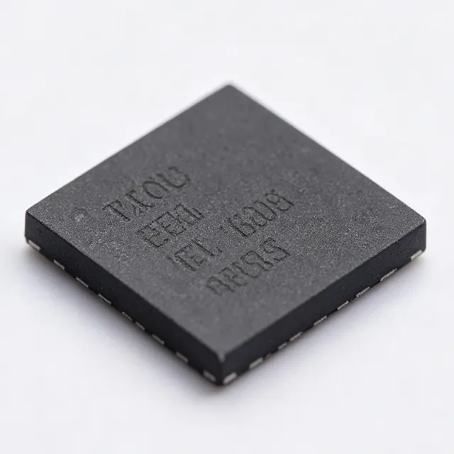
TIOL221RGER - Dual IO-Link PHY with LDO & SPI | TI
N.º da peça: TIOL221RGER ✓ Ativo| Qtd. | Preço unitário | Total |
|---|---|---|
| 1 | $0 | $0,00 |
| 10 | $0 | $0,00 |
| 100 | $0 | $0,00 |
| 500 | $0 | $0,00 |
| 1.000 | $0 | $0,00 |
TIOL221RGER Visão geral
An IO-Link PHY (physical layer transceiver) is a specialized industrial communication interface IC that handles line driving, wake-up detection, and protection for point-to-point digital communication networks. Within the system hierarchy, it sits below the microcontroller (logic layer) and above the physical cabling, forming part of the broader industrial networking and sensor interface semiconductor category.
Key features include dual CQ channels with integrated low-power output drivers featuring active reverse polarity protection, wake-up pulse generation and detection (sinking or sourcing >= 500 mA for a typical 80 us duration per IO-Link specification), and wake-up reporting to the local microcontroller by asserting the WU pin low. Internal protection covers undervoltage, overcurrent, and overtemperature conditions, with fault reporting to the host.
The integrated LDO reduces external BOM count, and the SPI interface allows flexible configuration and diagnostics. The device can also be configured to generate wake-up pulses and be used in IO-Link master applications, and it integrates an auxiliary DI (digital input) channel.
Typical applications include IO-Link sensor hubs, industrial proximity sensors, actuator nodes, and compact IO-Link master ports.
Design tip: ensure the CQ driver thermal budget accounts for wake-up pulse current, and use the fault reporting pins for system-level diagnostics.
Alternativas drop-in para TIOL221RGER — mesmo encapsulamento, compatível pino a pino. Peças de encapsulamento diferente que exigem retrabalho na PCB são excluídas.
Ferramenta de comparação rápida — selecione peças alternativas para comparação lado a lado:
TIOL221RGERT
✅ Drop-In ⚠️ Especificações não verificadas📋 Alternativa de referência (fora do catálogo)
TIOL221RGER Especificações
| Função | Dual Channel IO-Link Device PHY with Integrated LDO and SPI |
| Canais | 2 CQ channels + 1 auxiliary DI |
| Interface | SPI + IO-Link 3-wire (L+, L-, CQ) |
| Wake-up Pulse Current | >= 500 mA (sink or source) |
| Wake-up Duration | Typically 80 us |
| Wake-up Reporting | WU pin asserted low for tWUL |
| Protection Features | Undervoltage, overcurrent, overtemperature, reverse polarity (active) |
| Integrated LDO | Yes |
| Output Drivers | Dual low-power with active reverse polarity protection |
| IO-Link Mode | Device PHY; also configurable for IO-Link master wake-up generation |
| Encapsulamento | 24-VQFN (4x4 mm), VQFN-24 (RGE) |
| Tipo de montagem | Surface Mount |
| Fault Reporting | Yes (UV, OC, OT) |
Guia de Configuração de Pinos do TIOL221RGER 24-vqfn (4x4 mm), vqfn-24 (rge)
Configuração de pinos para TIOL221RGER (pacote 24-vqfn (4x4 mm), vqfn-24 (rge)). A numeração dos pinos, funções e diagramas de conexão estão definidos no datasheet do fabricante. Consulte-o para o footprint exato e diretrizes de soldagem.

Nenhum dado detalhado de pinagem disponível para TIOL221RGER.
Consulte a ficha técnica para a configuração completa dos pinos.
Aplicações típicas
TIOL221RGER é adequado para 6 aplicaçãos: IO-Link Sensor Hubs, Industrial Proximity Sensor Nodes, IO-Link Master Ports, Actuator Nodes and Valve Control, Factory Automation PLC I/O Modules, Prototyping and IO-Link Evaluation.
IO-Link Sensor Hubs
The TIOL221's dual CQ channels let one IC connect two IO-Link sensor ports, making it ideal for sensor hub nodes that aggregate multiple binary or analog sensors. Its integrated LDO and SPI reduce BOM count, while >= 500 mA wake-up pulse capability and WU pin reporting ensure full IO-Link wake-up compliance. Reverse polarity and overcurrent protection tolerate industrial field miswiring, and the auxiliary DI channel adds a bonus digital input without extra transceivers.
Recomendado
Industrial Proximity Sensor Nodes
For IO-Link proximity and photoelectric sensors, the TIOL221 acts as the complete physical layer over the three-wire interface. The 80 us, >= 500 mA wake-up pulse handling meets IO-Link specification timing, and fault reporting for undervoltage, overcurrent, and overtemperature enables smart diagnostics demanded by IO-Link Class A ports. The 4x4 mm VQFN-24 fits the compact housings typical of modern industrial sensors.
Recomendado
IO-Link Master Ports
The TIOL221 can be configured to generate wake-up pulses, per TI's product page, which is exactly what an IO-Link master port needs to activate sleeping device nodes. Dual channels allow one IC to serve two master ports or one port plus an auxiliary DI. Integrated drivers with active reverse polarity protection improve master port robustness against wiring faults, and SPI enables master-side configuration and diagnostics.
Recomendado
Actuator Nodes and Valve Control
In IO-Link actuator nodes (solenoid valves, indicator drives), the TIOL221's dual CQ low-power drivers with active reverse polarity protection switch loads under host SPI control. Overcurrent and overtemperature protection guard against stalled loads and shorted wiring, while the auxiliary DI channel can read local feedback such as limit switches. The integrated LDO supplies local logic, simplifying compact actuator PCB designs.
Recomendado
Factory Automation PLC I/O Modules
PLC remote I/O modules benefit from the TIOL221's channel density: two CQ ports plus a DI channel in a single 4x4 mm VQFN-24 reduces board area versus discrete transceivers. SPI-based configuration lets firmware adapt port behavior at runtime, and fault reporting supports predictive-maintenance diagnostics over the IO-Link backbone. Wake-up detection with WU pin signaling simplifies power-saving node designs.
Recomendado
Prototyping and IO-Link Evaluation
The TI TIOL221EVM evaluation module lets engineers exercise device and master wake-up configurations, SPI register settings, and protection behaviors before committing to a PCB. Since the EVM ships from DigiKey as of 2026-08-30, teams can validate wake-up timing (80 us, >= 500 mA) and tWUL signaling against a master in days rather than weeks, de-risking the transition to production firmware.
Recomendado
Resumo dos produtos recomendados
Dados de referência de engenharia para TIOL221RGER — comparação, orientação de projeto e informações de conformidade.
Guia de seleção
Comparação com alternativas
| Parâmetro | Este produto | TIOL1115DGQR | TIOL1113DMRR | L6360 |
|---|---|---|---|---|
| Package | 24-VQFN (4x4 mm, RGE) | VSSOP-10 | SOIC-8 | QFN-32 |
| Brand | Texas Instruments | Texas Instruments | Texas Instruments | STMicroelectronics |
| CQ Channels | 2 | 1 | 1 | 1 (plus DI/DO) |
| SPI Interface | Yes | No (pin-configurable) | No (pin-configurable) | Yes |
| Integrated LDO | Yes | Yes (LDO integrated) | Yes (LDO integrated) | Integrated DC-DC (buck) |
| Wake-up Pulse Capability | Generate and detect, >= 500 mA / 80 us | IO-Link device wake-up detect | IO-Link device wake-up detect | IO-Link wake-up detect |
| Protection | UV, OC, OT, reverse polarity (active) | UV, OC, OT, reverse polarity | UV, OC, OT, reverse polarity | UV, OC, OT, thermal |
Principais diferenciais
- Dual CQ channels in one 4x4 mm package (vs TIOL1115DGQR)
- SPI-configurable operation (vs TIOL1113DMRR)
- Auxiliary DI channel (vs L6360)
Notas de projeto
The TIOL221 integrates an LDO, but the CQ drivers must sink or source >= 500 mA during each ~80 us wake-up pulse. Size the VQFN-24 exposed pad and PCB copper for these transient currents, and verify the upstream supply does not droop below undervoltage thresholds during wake-up, which could trigger false fault reporting.
Place the L+ and CQ line protection and bulk capacitance close to the IC and use short, wide traces for the CQ channels. Connect the thermal pad to a solid ground plane with multiple vias to dissipate wake-up pulse energy and improve overtemperature protection accuracy.
Wake-up timing is IO-Link-specified (typically 80 us at >= 500 mA) and the WU pin asserts low only for tWUL - ensure the MCU polls or uses an interrupt on WU rather than level-holding assumptions. When configuring via SPI, confirm register defaults match your CQ mode before enabling drivers to avoid unintended wake-up pulse generation.
Informações de conformidade
Compliance status not stated in verified web data; consult TI product page and datasheet for RoHS/REACH details.







