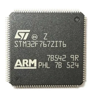
S912XET256W1MAGR - 16-Bit 50MHz 256KB Flash S12X MCU | NXP
MPN: S912XET256W1MAGR ✓ Hoạt độngS912XET256W1MAGR Tóm tắt
What is a 16-bit MCU? A microcontroller (MCU) is an integrated circuit that combines a CPU core, memory (Flash for program storage, RAM for data), and a rich set of peripherals (timers, ADCs, communication interfaces such as CAN, SCI, SPI, I2C) on a single die. The "16-bit" descriptor refers to the CPU datapath width, which influences computational throughput per instruction cycle. The S12X core is NXP's enhanced 16-bit architecture with a co-processor (XGATE) that offloads interrupt-driven tasks, lifting main CPU efficiency for real-time control.
Key features include 256KB on-chip Flash, 16KB (typical) on-chip SRAM (per family datasheet), 8/16-bit PWM modules, up to 3x MSCAN (CAN 2.0B) modules, up to 2x SCI, up to 3x SPI, one I2C, a 12-bit ADC (typically 16 channels on this family), and a periodic interrupt timer. The 144-pin LQFP package (20x20 mm body, 0.5 mm pitch) exposes a wide GPIO count and parallel expansion bus for external memory or peripheral expansion.
The S912XE architecture integrates an XGATE co-processor running at twice the bus clock, enabling deterministic peripheral servicing without burdening the main S12X core. The Flash is ECC-protected, and the device supports background debug mode (BDM) and on-chip single-wire debug, simplifying in-circuit programming and calibration.
Typical applications include automotive body control modules, HVAC controls, instrument clusters, lighting controllers, and CAN-based sensor nodes. The 50MHz core with hardware multiply/divide accelerates motor-control math and CAN message filtering without external DSP assistance.
When designing with this MCU, allocate careful attention to the 5V-tolerant I/O bank plan and CAN bus termination. Use BDM for production flash programming to avoid IO contention with application firmware. Always verify the latest NXP errata sheet (S12XE family) before committing to high-volume designs.
Bộ thay thế dễ dàng lắp đặt cho S912XET256W1MAGR — cùng gói, chân-to-chân tương thích. Các bộ phận yêu cầu hàn PCB bị loại trừ.
Các biến thể trong loạt này
Các mẫu cùng loạt có thể lắp đặt dễ dàng tương thích với S912XET256W1MAGR (cùng hình factor và footprint) — khác nhau ở ADC, Operating Temperature, Package, Mounting Type, RoHS Status.
S912XET256W1MAG
✅ Drop-In📋 Tham chiếu thay thế (không có trong danh mục)
S912XEQ512J2MAL
✅ Drop-InLiên hệ để biết giá
Xem tài liệu →MC9S12XEQ512CAG
✅ Drop-InLiên hệ để biết giá
Xem tài liệu →MC9S12XEP768J4CAL
✅ Drop-In📋 Tham chiếu thay thế (không có trong danh mục)
MC9S12XHZ256VAG
✅ Drop-InLiên hệ để biết giá
Xem tài liệu →S912XET256W1MAGR Tỷ lệ tối đa & tính chất điện
| Core Architecture | HCS12X (16-bit, XGATE co-processor) |
| Core Frequency | 50 MHz |
| Program Memory (Flash) | 256 KB (256K x 8) |
| Nhiệt độ hoạt động | -40C to +125C (Automotive Grade) |
| Hộp | 144-LQFP (20x20 mm, 0.5 mm pitch) |
| Kiểu lắp đặt | Surface Mount |
| Số lượng chân | 144 |
| Terminal Form | GULL WING |
| Lead Finish | Matte Tin (Tape and Reel) |
| Qualification | AEC-Q100 Automotive |
| CAN Modules (MSCAN) | Up to 3 (typical of S12XE 144-pin family) |
| SCI / SPI / I2C | 2 / 3 / 1 (per family datasheet) |
| ADC | 12-bit, multi-channel (per family datasheet) |
| PWM Channels | 8/16-bit PWM modules (per family datasheet) |
| Debug Interface | BDM (Background Debug Mode) |
| Trạng thái RoHS | Compliant (per data sheet family) |
Cấu hình chân S912XET256W1MAGR
| Chân 1 | VSS1 — Ground 1 (digital) |
| Chân 2 | VDD1 — Digital supply 1 (5V core) |
| Chân 3 | OSC1 — Crystal oscillator input |
| Chân 4 | OSC2 — Crystal oscillator output |
| Chân 5 | RESET — External reset input (active low) |
| Chân 6 | TEST — Test mode / VPP |
| Chân 7 | BKGD — Background Debug Mode (single-wire) |
| Chân 8 | PAD0 — PWM / Timer channel A0 |
| Chân 9 | PAD1 — PWM / Timer channel A1 |
| Chân 10 | PAD2 — PWM / Timer channel A2 |
| Chân 11 | PAD3 — PWM / Timer channel A3 |
| Chân 12 | PAD4 — PWM / Timer channel A4 |
| Chân 13 | PAD5 — PWM / Timer channel A5 |
| Chân 14 | PAD6 — PWM / Timer channel A6 |
| Chân 15 | PAD7 — PWM / Timer channel A7 |
| Chân 16 | PJ0 — GPIO / SPI control |
| Chân 17 | PJ1 — GPIO / SPI control |
| Chân 18 | PJ2 — GPIO / SPI control |
| Chân 19 | PJ3 — GPIO / SPI control |
| Chân 20 | PJ4 — GPIO / SPI control |
| Chân 21 | PJ5 — GPIO / SPI control |
| Chân 22 | PJ6 — GPIO / SPI control |
| Chân 23 | PJ7 — GPIO / SPI control |
| Chân 24 | PK0 — GPIO / SPI control |
| Chân 25 | PK1 — GPIO / SPI control |
| Chân 26 | PK2 — GPIO / SPI control |
| Chân 27 | PK3 — GPIO / SPI control |
| Chân 28 | PK4 — GPIO / SPI control |
| Chân 29 | PK5 — GPIO / SPI control |
| Chân 30 | PK6 — GPIO / SPI control |
| Chân 31 | PK7 — GPIO / SPI control |
| Chân 32 | PA0 — GPIO / Address bus low |
| Chân 33 | PA1 — GPIO / Address bus low |
| Chân 34 | PA2 — GPIO / Address bus low |
| Chân 35 | PA3 — GPIO / Address bus low |
| Chân 36 | PA4 — GPIO / Address bus low |
| Chân 37 | PA5 — GPIO / Address bus low |
| Chân 38 | PA6 — GPIO / Address bus low |
| Chân 39 | PA7 — GPIO / Address bus low |
| Chân 40 | PB0 — GPIO / Address bus high |
| Chân 41 | PB1 — GPIO / Address bus high |
| Chân 42 | PB2 — GPIO / Address bus high |
| Chân 43 | PB3 — GPIO / Address bus high |
| Chân 44 | PB4 — GPIO / Address bus high |
| Chân 45 | PB5 — GPIO / Address bus high |
| Chân 46 | PB6 — GPIO / Address bus high |
| Chân 47 | PB7 — GPIO / Address bus high |
| Chân 48 | PC0 — GPIO / Data bus |
| Chân 49 | PC1 — GPIO / Data bus |
| Chân 50 | PC2 — GPIO / Data bus |
| Chân 51 | PC3 — GPIO / Data bus |
| Chân 52 | PC4 — GPIO / Data bus |
| Chân 53 | PC5 — GPIO / Data bus |
| Chân 54 | PC6 — GPIO / Data bus |
| Chân 55 | PC7 — GPIO / Data bus |
| Chân 56 | PD0 — GPIO / Data bus |
| Chân 57 | PD1 — GPIO / Data bus |
| Chân 58 | PD2 — GPIO / Data bus |
| Chân 59 | PD3 — GPIO / Data bus |
| Chân 60 | PD4 — GPIO / Data bus |
| Chân 61 | PD5 — GPIO / Data bus |
| Chân 62 | PD6 — GPIO / Data bus |
| Chân 63 | PD7 — GPIO / Data bus |
| Chân 64 | VDDR — I/O supply voltage (5V) |
| Chân 65 | VSS2 — Ground 2 (digital) |
| Chân 66 | PE0 — GPIO / SCI / SPI |
| Chân 67 | PE1 — GPIO / SCI / SPI |
| Chân 68 | PE2 — GPIO / SCI / SPI |
| Chân 69 | PE3 — GPIO / SCI / SPI |
| Chân 70 | PE4 — GPIO / SCI / SPI |
| Chân 71 | PE5 — GPIO / SCI / SPI |
| Chân 72 | PE6 — GPIO / SCI / SPI |
| Chân 73 | PE7 — GPIO / SCI / SPI |
| Chân 74 | PF0 — GPIO / PWM ECT |
| Chân 75 | PF1 — GPIO / PWM ECT |
| Chân 76 | PF2 — GPIO / PWM ECT |
| Chân 77 | PF3 — GPIO / PWM ECT |
| Chân 78 | PF4 — GPIO / PWM ECT |
| Chân 79 | PF5 — GPIO / PWM ECT |
| Chân 80 | PF6 — GPIO / PWM ECT |
| Chân 81 | PF7 — GPIO / PWM ECT |
| Chân 82 | PG0 — GPIO / PWM ECT |
| Chân 83 | PG1 — GPIO / PWM ECT |
| Chân 84 | PG2 — GPIO / PWM ECT |
| Chân 85 | PG3 — GPIO / PWM ECT |
| Chân 86 | PG4 — GPIO / PWM ECT |
| Chân 87 | PG5 — GPIO / PWM ECT |
| Chân 88 | PG6 — GPIO / PWM ECT |
| Chân 89 | PG7 — GPIO / PWM ECT |
| Chân 90 | PH0 — GPIO / CAN / SCI |
| Chân 91 | PH1 — GPIO / CAN / SCI |
| Chân 92 | PH2 — GPIO / CAN / SCI |
| Chân 93 | PH3 — GPIO / CAN / SCI |
| Chân 94 | PH4 — GPIO / CAN / SCI |
| Chân 95 | PH5 — GPIO / CAN / SCI |
| Chân 96 | PH6 — GPIO / CAN / SCI |
| Chân 97 | PH7 — GPIO / CAN / SCI |
| Chân 98 | PI0 — GPIO / CAN / SCI |
| Chân 99 | PI1 — GPIO / CAN / SCI |
| Chân 100 | PI2 — GPIO / CAN / SCI |
| Chân 101 | PI3 — GPIO / CAN / SCI |
| Chân 102 | PI4 — GPIO / CAN / SCI |
| Chân 103 | PI5 — GPIO / CAN / SCI |
| Chân 104 | PI6 — GPIO / CAN / SCI |
| Chân 105 | PI7 — GPIO / CAN / SCI |
| Chân 106 | TXCAN0 — CAN0 transmit output |
| Chân 107 | RXCAN0 — CAN0 receive input |
| Chân 108 | TXCAN1 — CAN1 transmit output |
| Chân 109 | RXCAN1 — CAN1 receive input |
| Chân 110 | TXCAN2 — CAN2 transmit output |
| Chân 111 | RXCAN2 — CAN2 receive input |
| Chân 112 | TXD0 — SCI0 transmit output |
| Chân 113 | RXD0 — SCI0 receive input |
| Chân 114 | TXD1 — SCI1 transmit output |
| Chân 115 | RXD1 — SCI1 receive input |
| Chân 116 | MOSI0 — SPI0 master-out slave-in |
| Chân 117 | MISO0 — SPI0 master-in slave-out |
| Chân 118 | SCK0 — SPI0 serial clock |
| Chân 119 | SS0 — SPI0 slave select |
| Chân 120 | SDA — I2C data |
| Chân 121 | SCL — I2C clock |
| Chân 122 | AN0 — ADC analog input 0 |
| Chân 123 | AN1 — ADC analog input 1 |
| Chân 124 | AN2 — ADC analog input 2 |
| Chân 125 | AN3 — ADC analog input 3 |
| Chân 126 | AN4 — ADC analog input 4 |
| Chân 127 | AN5 — ADC analog input 5 |
| Chân 128 | AN6 — ADC analog input 6 |
| Chân 129 | AN7 — ADC analog input 7 |
| Chân 130 | VRH — ADC high reference voltage |
| Chân 131 | VRL — ADC low reference voltage |
| Chân 132 | VDDA — Analog supply |
| Chân 133 | VSSA — Analog ground |
| Chân 134 | TCLK — ECT external clock input |
| Chân 135 | IOC0 — Capture / compare input |
| Chân 136 | IOC1 — Capture / compare input |
| Chân 137 | IOC2 — Capture / compare input |
| Chân 138 | IOC3 — Capture / compare input |
| Chân 139 | IOC4 — Capture / compare input |
| Chân 140 | IOC5 — Capture / compare input |
| Chân 141 | IOC6 — Capture / compare input |
| Chân 142 | IOC7 — Capture / compare input |
| Chân 143 | PLLCLK — PLL clock output / test |
| Chân 144 | NC — Not connected (per package datasheet) |
Ứng dụng tiêu biểu
S912XET256W1MAGR phù hợp cho 7 Áp dụngs: Automotive Body Control Module (BCM), HVAC Climate Control ECU, Automotive Instrument Cluster Display, CAN-Based Sensor Node, Motor Control Front-End (BLDC/PMSM Drivers), Automotive Lighting Controller (LED Matrix / Adaptive Headlamp), Chassis Gateway / Network Bridge.
Automotive Body Control Module (BCM)
The S912XET256W1MAGR's 256 KB Flash holds the BCM firmware stack including CAN bootloader, diagnostic services, and door/lamp/window control logic without external memory. The 50 MHz S12X core with XGATE co-processor handles CAN message filtering and debounce timing while the main CPU runs multi-channel PWM for lamp-dimming. Operating range -40C to +125C allows placement inside cabin or rear-trunk ECUs. Per NXP reference designs, the 3x MSCAN bridges connect to chassis CAN and powertrain CAN simultaneously.
Được đề xuất
HVAC Climate Control ECU
The S12X core's 50 MHz headroom with hardware multiply supports PID climate-loop math at 10 ms update rates while running CAN communication for HVAC panel and blower control. Flash capacity (256 KB) fits the lookup-table-based airflow and temperature-target algorithms plus diagnostic service stack. According to NXP application note AN3891, the S12XE family's PWM frequency covers the blower and mode-door motor control range without an external driver MCU.
Được đề xuất
Automotive Instrument Cluster Display
The 50 MHz S12X core drives CAN messaging (RPM, speed, fuel level) and steers LCD-segment or stepper-motor gauges inside the cluster. 256 KB of Flash accommodates gauge graphics, custom warning logic, and the CAN diagnostic interpreter. The XGATE co-processor pre-processes incoming CAN frames in parallel with main-loop duty cycles, keeping 50 ms display refresh jitter-free per S12XE datasheet benchmarks.
Được đề xuất
CAN-Based Sensor Node
For distributed sensor nodes (occupant detection, rain-light sensor, tire pressure monitoring satellite), the S912XET256W1MAGR integrates CAN MSCAN plus SPI/I2C interfaces for sensor readout. According to NXP automotive reference designs, the BDM (single-wire background debug mode) simplifies in-vehicle module calibration via the service connector. 256 KB Flash reserves room for CAN bootloaders needed for end-of-line firmware updates.
Được đề xuất
Motor Control Front-End (BLDC/PMSM Drivers)
The S12X core with hardware multiply/divide and 12-bit ADC pairs with PWM modules to run field-oriented control of small BLDC motors for HVAC blowers or coolant pumps. Per the S12XE family reference manual, 8/16-bit PWM dead-time insertion and center-aligned modes are optimized for motor drive without external logic. The 50 MHz compute budget cycles at 10 us FOC updates while leaving 30 percent CPU time for CAN housekeeping.
Được đề xuất
Automotive Lighting Controller (LED Matrix / Adaptive Headlamp)
The S12X core's PWMs and timers drive multi-channel LED arrays with dimming and matrix-beam switching at CAN-update rates. 256 KB Flash accommodates the matrix-segment LUT and adaptive-beam state machine. AEC-Q100 qualification and the 144-LQFP package's GPIO count (over 100) let one MCU drive 30+ LED strings without external shift registers, per NXP S12XE application briefs.
Được đề xuất
Chassis Gateway / Network Bridge
With three MSCAN modules, the S912XET256W1MAGR acts as a CAN-to-CAN gateway bridging powertrain CAN, chassis CAN, and diagnostic CAN. The XGATE co-processor accelerates frame transfer between buses without CPU bottleneck. Per NXP application notes, the S12X core's GPIO count and external bus interface allow additional LIN or FlexRay supplementary channels via companion transceivers.
Được đề xuất
Tóm tắt các sản phẩm được đề xuất
Dữ liệu tham khảo kỹ thuật cho S912XET256W1MAGR — so sánh, hướng dẫn thiết kế và thông tin tuân thủ.
Hướng dẫn chọn lựa
So sánh với các sản phẩm thay thế
| Tham số | Sản phẩm này | S912XET256W1MAG | S912XEQ512J2MAL | MC9S12XEQ512CAG |
|---|---|---|---|---|
| Brand | NXP Semiconductors | NXP Semiconductors (same brand) | NXP Semiconductors (same brand) | NXP Semiconductors (same brand) |
| Package | 144-LQFP (20x20 mm) | 144-LQFP - same | 144-LQFP - same | 144-LQFP - same |
| Core | HCS12X 16-bit + XGATE | HCS12X + XGATE (same) | HCS12X + XGATE (same) | HCS12X + XGATE (same) |
| Flash Memory | 256 KB | 256 KB (same) | 512 KB (+100%) | 512 KB (+100%) |
| Max CPU Frequency | 50 MHz | 50 MHz (same) | 50 MHz (same) | 50 MHz (same) |
| Operating Temperature | -40C to +125C (Automotive) | -40C to +125C (Automotive) - same | -40C to +125C (Automotive) - same | -40C to +125C (Automotive) - same |
| CAN Modules (MSCAN) | Up to 3 | Up to 3 (same) | Up to 3 (same) | Up to 3 (same) |
| Packaging Format | Tape and Reel (R suffix) | Tray (no R suffix) | Tray | Tray |
| Qualification | AEC-Q100 | AEC-Q100 - same | AEC-Q100 - same | AEC-Q100 - same |
Bảo phân biệt quan trọng
- R-suffix tape-and-reel packaging (vsS912XET256W1MAG)
- XGATE co-processor for interrupt acceleration (vsMC9S08AC8MFGE)
- 256 KB Flash at 50 MHz with -40/+125C grade (vsMC9S12XHZ256VAG)
Ghi chú thiết kế
The S912XET256W1MAGR requires separate decoupling on VDDR (5V IO supply) and VDD1/VSS1/VDDA/VSSA pairs. Use 100 nF ceramic decoupling caps as close as possible to each power pin, plus a 10 uF bulk capacitor near the IC. The 5V analog supply (VDDA) should be filtered with an additional ferrite bead from VDDR to suppress switching noise from the digital core. Per NXP S12XE hardware guidelines, the PLL requires a clean oscillator supply and decoupling capacitance as shown in the S12XE family reference manual.
Always verify the latest NXP errata sheet for the S12XE family before committing to high-volume designs. Known errata include workarounds for specific MSCAN FIFO and PWM duty cycle behaviors that have been addressed in newer revisions. Note the part marking on the package indicates revision; firmware masks must match the silicon revision per NXP application note AN3891.
Place the 144-LQFP land pattern with at least 4-layer PCB and a continuous ground plane beneath the IC. Route the high-current CAN traces first with matched impedance to the TJA1057 or similar transceiver, keeping them at least 5 mm away from analog signal lines. The oscillator traces (OSC1/OSC2) must be routed short with surrounding ground flood. Per NXP hardware design tips, ensure the BKGD pin is accessible via a header or testpad for in-circuit debug.
Estimated: At 50 MHz CPU frequency, 5V supply, and typical automotive application activity ratio, the 144-LQFP junction temperature rises approximately 15-25 C above ambient under full load, depending on PCB copper area around the part. AEC-Q100 grade 0 silicon is rated to +150C junction. For under-the-hood applications exceeding 85C ambient, ensure thermal relief in the form of PCB thermal vias and copper pours.
Thông tin tuân thủ
AEC-Q100 automotive qualified per NXP product page. RoHS and lead-free compliant per distributor listings. The 'W' device code designates -40C to +125C automotive grade 0 silicon per NXP S12XE ordering guide.