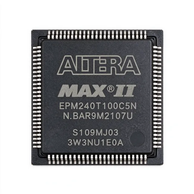
EPM240T100C5 - MAX II CPLD, 192 Macrocells, 100-TQFP | Altera
MPN: EPM240T100C5 ✓ 啟用中| 數量 | 單價 | 小計 |
|---|---|---|
| 1 | $8.4375 | $8.44 |
| 10 | $6.0938 | $60.94 |
| 100 | $5.3906 | $539.06 |
| 500 | $5.1563 | $2,578.15 |
| 1,000 | $4.9219 | $4,921.90 |
EPM240T100C5 概覽
A CPLD (Complex Programmable Logic Device) is a non-volatile programmable logic device that uses a macrocell-based architecture with continuous, distributed interconnect. In the system-level hierarchy, a CPLD sits below an FPGA (Field-Programmable Gate Array) in density, above small PAL/GAL devices, and below microcontroller units (MCUs) in flexibility. MAX II CPLDs target glue-logic, interface bridging, power-sequencing, and bus-management functions where deterministic timing and zero in-system configuration delay are mandatory.
Key features include 192 logic elements, 4.7 ns pin-to-pin logic delay (tPD1), 201.1 MHz maximum internal operating frequency, support for 2.5 V and 3.3 V core supply operation, MultiVolt I/O supporting 1.5 V/1.8 V/2.5 V/3.3 V levels, JTAG-based IEEE 1149.1 boundary-scan testing and in-system programmability (ISP), and a global chip-wide DEV_OE output enable pin for board-level tri-state control.
The device uses a non-volatile Flash-based architecture with 8 Kbits of embedded storage, four I/O banks for voltage-domain isolation, and on-chip pull-up resistors (User I/O pin 4 control) configurable in Quartus II. Each macrocell contains a programmable AND/OR array, a flip-flop, and feedback paths to the logic array, enabling compact state-machine and decoding-logic implementation.
Typical applications include I/O expansion for microcontrollers and microprocessors, address decoding and chip-select generation in memory subsystems, bus-interface bridging (LVCMOS, LVTTL, PCI-compatible), power-supply sequencing in multi-rail systems, and configurable glue logic in industrial automation equipment. The instant-on behavior also suits FPGA configuration control, where the CPLD provides boot-up housekeeping before the main FPGA completes its configuration cycle.
When designing with the EPM240T100C5, observe I/O bank voltage constraints: each of the four banks shares a common VCCIO that must match the signal level of devices connected to that bank. The 5.0-V tolerant I/O feature requires VCCIO at 3.3 V; do not apply 5 V to any I/O pin. Use Quartus II (legacy) or the Intel Quartus Prime Lite Edition for design entry, synthesis, and JTAG programming.
This page consolidates distributor pricing, verified specifications, and curated drop-in alternatives not found in the manufacturer datasheet alone, helping engineers evaluate EPM240T100C5 for both new designs and legacy upgrades from MAX 7000S or classic PLDs.
直接替換替代品,適用於 EPM240T100C5 — 相同封裝,腳位對腳位相容。需重新設計 PCB 的不同封裝零件不列入。
此系列的變體
與下列產品可直接替換的同系列型號: EPM240T100C5 (相同外形與佔位) — 差異在於 Operating Temperature, Package, Process Technology, Programming Interface.
快速比較工具 — 選擇替代零件進行並排比較:
EPM240T100C5N
聯絡詢價
查看資料表 →EPM240T100C4N
聯絡詢價
查看資料表 →EPM240T100C4
聯絡詢價
查看資料表 →EPM240T100C3N
聯絡詢價
查看資料表 →EPM240GT100C5N
聯絡詢價
查看資料表 →EPM240T100C5 最大額定值與電氣特性
| Family | MAX II |
| Device Type | CPLD (Complex Programmable Logic Device) |
| Macrocells | 192 |
| Maximum User I/O Pins | 80 |
| Logic Elements | 240 |
| Non-volatile Memory | 8 Kbits (embedded Flash) |
| Pin-to-Pin Logic Delay (tPD1) | 4.7 ns |
| Maximum Internal Frequency | 201.1 MHz |
| Process Technology | 0.18 µm, 6-layer metal Flash |
| Core Supply Voltage | 2.5 V / 3.3 V |
| I/O Voltage Support | 1.5 V / 1.8 V / 2.5 V / 3.3 V (MultiVolt I/O) |
| I/O Banks | 4 |
| 封裝 | 100-pin TQFP (14 mm × 14 mm × 1 mm) |
| Programming Interface | JTAG (IEEE 1149.1) / ISP |
| 工作溫度 | 0C to +85C (Commercial) |
| Chip-wide Output Enable | DEV_OE pin |
EPM240T100C5 腳位配置
| 腳位 1 | I/O — User I/O (Bank 1) |
| 腳位 2 | I/O — User I/O (Bank 1) |
| 腳位 3 | I/O — User I/O (Bank 1) |
| 腳位 4 | I/O — User I/O (Bank 1) |
| 腳位 5 | I/O — User I/O (Bank 1) |
| 腳位 6 | VCCIO1 — Bank 1 I/O supply voltage |
| 腳位 7 | I/O — User I/O (Bank 1) |
| 腳位 8 | GND — Ground |
| 腳位 9 | I/O — User I/O (Bank 1) |
| 腳位 10 | I/O — User I/O (Bank 1) |
| 腳位 11 | I/O — User I/O (Bank 1) |
| 腳位 12 | I/O — User I/O (Bank 1) |
| 腳位 13 | I/O — User I/O (Bank 1) |
| 腳位 14 | I/O — User I/O (Bank 1) |
| 腳位 15 | I/O — User I/O (Bank 1) |
| 腳位 16 | VCCIO1 — Bank 1 I/O supply voltage |
| 腳位 17 | I/O — User I/O (Bank 1) |
| 腳位 18 | I/O — User I/O (Bank 1) |
| 腳位 19 | I/O — User I/O (Bank 1) |
| 腳位 20 | I/O — User I/O (Bank 1) |
| 腳位 21 | I/O — User I/O (Bank 2) |
| 腳位 22 | VCCIO2 — Bank 2 I/O supply voltage |
| 腳位 23 | I/O — User I/O (Bank 2) |
| 腳位 24 | GND — Ground |
| 腳位 25 | I/O — User I/O (Bank 2) |
| 腳位 26 | I/O — User I/O (Bank 2) |
| 腳位 27 | I/O — User I/O (Bank 2) |
| 腳位 28 | I/O — User I/O (Bank 2) |
| 腳位 29 | I/O — User I/O (Bank 2) |
| 腳位 30 | VCCIO2 — Bank 2 I/O supply voltage |
| 腳位 31 | I/O — User I/O (Bank 2) |
| 腳位 32 | I/O — User I/O (Bank 2) |
| 腳位 33 | I/O — User I/O (Bank 2) |
| 腳位 34 | I/O — User I/O (Bank 2) |
| 腳位 35 | I/O — User I/O (Bank 2) |
| 腳位 36 | I/O — User I/O (Bank 2) |
| 腳位 37 | I/O — User I/O (Bank 2) |
| 腳位 38 | VCCIO2 — Bank 2 I/O supply voltage |
| 腳位 39 | I/O — User I/O (Bank 2) |
| 腳位 40 | I/O — User I/O (Bank 2) |
| 腳位 41 | GND — Ground |
| 腳位 42 | I/O — User I/O (Bank 3) |
| 腳位 43 | I/O — User I/O (Bank 3) |
| 腳位 44 | VCCIO3 — Bank 3 I/O supply voltage |
| 腳位 45 | I/O — User I/O (Bank 3) |
| 腳位 46 | I/O — User I/O (Bank 3) |
| 腳位 47 | I/O — User I/O (Bank 3) |
| 腳位 48 | I/O — User I/O (Bank 3) |
| 腳位 49 | I/O — User I/O (Bank 3) |
| 腳位 50 | VCCIO3 — Bank 3 I/O supply voltage |
| 腳位 51 | I/O — User I/O (Bank 3) |
| 腳位 52 | I/O — User I/O (Bank 3) |
| 腳位 53 | I/O — User I/O (Bank 3) |
| 腳位 54 | I/O — User I/O (Bank 3) |
| 腳位 55 | I/O — User I/O (Bank 3) |
| 腳位 56 | I/O — User I/O (Bank 3) |
| 腳位 57 | VCCIO3 — Bank 3 I/O supply voltage |
| 腳位 58 | I/O — User I/O (Bank 3) |
| 腳位 59 | I/O — User I/O (Bank 3) |
| 腳位 60 | I/O — User I/O (Bank 3) |
| 腳位 61 | GND — Ground |
| 腳位 62 | I/O — User I/O (Bank 4) |
| 腳位 63 | I/O — User I/O (Bank 4) |
| 腳位 64 | VCCIO4 — Bank 4 I/O supply voltage |
| 腳位 65 | I/O — User I/O (Bank 4) |
| 腳位 66 | I/O — User I/O (Bank 4) |
| 腳位 67 | I/O — User I/O (Bank 4) |
| 腳位 68 | I/O — User I/O (Bank 4) |
| 腳位 69 | I/O — User I/O (Bank 4) |
| 腳位 70 | VCCIO4 — Bank 4 I/O supply voltage |
| 腳位 71 | I/O — User I/O (Bank 4) |
| 腳位 72 | I/O — User I/O (Bank 4) |
| 腳位 73 | I/O — User I/O (Bank 4) |
| 腳位 74 | I/O — User I/O (Bank 4) |
| 腳位 75 | I/O — User I/O (Bank 4) |
| 腳位 76 | I/O — User I/O (Bank 4) |
| 腳位 77 | VCCIO4 — Bank 4 I/O supply voltage |
| 腳位 78 | I/O — User I/O (Bank 4) |
| 腳位 79 | I/O — User I/O (Bank 4) |
| 腳位 80 | I/O — User I/O (Bank 4) |
| 腳位 81 | GND — Ground |
| 腳位 82 | DEV_OE — Chip-wide output enable (active high) |
| 腳位 83 | I/O — User I/O (Bank 4) |
| 腳位 84 | I/O — User I/O (Bank 4) |
| 腳位 85 | TDI — JTAG Test Data In |
| 腳位 86 | TMS — JTAG Test Mode Select |
| 腳位 87 | TCK — JTAG Test Clock |
| 腳位 88 | TDO — JTAG Test Data Out |
| 腳位 89 | VCCINT — Core supply voltage (2.5 V or 3.3 V) |
| 腳位 90 | GND — Ground |
| 腳位 91 | I/O — User I/O (Bank 1) |
| 腳位 92 | I/O — User I/O (Bank 1) |
| 腳位 93 | I/O — User I/O (Bank 1) |
| 腳位 94 | I/O — User I/O (Bank 1) |
| 腳位 95 | I/O — User I/O (Bank 1) |
| 腳位 96 | VCCIO1 — Bank 1 I/O supply voltage |
| 腳位 97 | I/O — User I/O (Bank 1) |
| 腳位 98 | I/O — User I/O (Bank 1) |
| 腳位 99 | I/O — User I/O (Bank 1) |
| 腳位 100 | I/O — User I/O (Bank 1) |
典型應用
EPM240T100C5 適用於 6 應用s: Microcontroller I/O Expansion and Glue Logic, Power Supply Sequencing in Multi-Rail Systems, FPGA Configuration and Boot Control, Bus Interface Bridging (LVCMOS, LVTTL, PCI), Industrial Automation Control Logic, Address Decoding in Memory Subsystems.
Microcontroller I/O Expansion and Glue Logic
The EPM240T100C5 expands a host MCU's limited GPIO by decoding address lines and generating chip-select strobes for peripherals like SRAM, Flash, and sensors. Its 192 macrocells and 80 user I/O pins provide ample headroom for 8-bit and 16-bit bus decoding, while the 4.7 ns pin-to-pin delay ensures address-to-CS propagation stays well under one 50 MHz system clock period. The instant-on non-volatile Flash eliminates boot-PROM overhead, so the CPLD is ready to drive chip-selects before the MCU finishes its PLL lock - critical for deterministic power-on behavior. Designers typically place the CPLD between the MCU EMI bus and 4-8 peripheral devices, freeing the MCU's GPIO for serial interfaces.
推薦
Power Supply Sequencing in Multi-Rail Systems
The EPM240T100C5 sequences 3-6 voltage rails (1.0 V core, 1.5 V DDR, 1.8 V I/O, 2.5 V PLLs, 3.3 V analog) in the correct order during power-up and reverse order during power-down. Each macrocell implements a comparator-and-counter state machine that watches a PGOOD signal and asserts the next rail's enable after a configurable delay. The non-volatile Flash means the sequencing logic is active within microseconds of VCCINT reaching 2.5 V, eliminating the race condition between bulk-capacitor charging and rail-monitors. Designers typically route 4 power-good inputs to the CPLD and 6 enable outputs to DC-DC converter PG pins.
推薦
FPGA Configuration and Boot Control
The EPM240T100C5 acts as a configuration controller for SRAM-based FPGAs that require multi-mode boot (JTAG / parallel / serial). It reads the FPGA's configuration mode-pins and drives them based on a user-defined mode sequence, holds the FPGA in RESET until VCCINT is stable, and generates the PROG_B pulse on demand. The 8 Kbit embedded Flash stores the mode-selection logic permanently, so no external PROM is needed. Designers route DONE, INIT_B, and CONFIG_B lines from the FPGA to the CPLD, with the CPLD returning CTRL0/CTRL1 selections. This pattern is common in industrial and telecom designs where field-upgrade flexibility is required.
推薦
Bus Interface Bridging (LVCMOS, LVTTL, PCI)
The EPM240T100C5 bridges between mismatched bus standards - for example, translating a 3.3 V LVCMOS microcontroller bus to 1.8 V LVCMOS peripherals or providing a 5-V-tolerant input buffer for legacy PCI signals (when VCCIO is set to 3.3 V). Four I/O banks allow voltage-domain isolation so 1.5 V, 1.8 V, 2.5 V, and 3.3 V devices can all connect to the same CPLD without external level-shifters. With 4.7 ns tPD, the bridge introduces negligible latency into memory-mapped interfaces. Typical designs use 8-16 macrocells per 8-bit bus-converter instance, leaving headroom for handshaking and parity logic.
推薦
Industrial Automation Control Logic
In factory-automation PLCs, distributed I/O blocks, and motor-control auxiliary boards, the EPM240T100C5 implements deterministic state machines for safety-interlock logic, encoder-decoder counting, and PWM-edge multiplexing. Its 0-85C commercial or -40-85C industrial variants and 4.7 ns tPD suit real-time control loops. The on-chip pull-up resistors (configurable per User I/O pin 4) reduce BOM cost by eliminating external 10K arrays. Designers typically deploy 1-2 CPLDs per PLC chassis to consolidate discrete logic that would otherwise require dozens of 74HC-series gates.
推薦
Address Decoding in Memory Subsystems
The EPM240T100C5 decodes 24-32 bit address lines into individual chip-selects for Flash, SRAM, DRAM, and peripheral registers in embedded systems. A typical implementation uses 32 macrocells to generate 8 chip-selects with address-range masking via internal feedback comparators. The instant-on behavior ensures the chip-selects are valid at the first clock edge after reset, eliminating the boot-window violation that occurs with SRAM-based FPGAs. Designers often combine this application with bus-cycle termination logic (RDY/BWAIT stretching) using the same CPLD, saving board area versus discrete MSI logic.
推薦
推薦產品摘要
工程參考資料,適用於 EPM240T100C5 — 比較、設計指引及合規資訊。
選型指南
與替代品比較
| 參數 | 本產品 | EPM240T100C5N | EPM240T100C4N | EPM240T100C4 | EPM240T100C3N | EPM240GT100C5N | EPM240GT100C5 |
|---|---|---|---|---|---|---|---|
| Package | TQFP-100 | TQFP-100 - same | TQFP-100 - same | TQFP-100 - same | TQFP-100 - same | TQFP-100 - same | TQFP-100 - same |
| Brand | Altera (Intel) | Altera (Intel) | Altera (Intel) | Altera (Intel) | Altera (Intel) | Altera (Intel) | Altera (Intel) |
| Family | MAX II | MAX II | MAX II | MAX II | MAX II | MAX II G | MAX II G |
| Speed Grade | C5 (4.7 ns tPD) | C5 (4.7 ns tPD) | C4 (slower tPD) | C4 (slower tPD) | C3 (slowest tPD) | C5 | C5 |
| Lead-Free (RoHS) | No (leaded) | Yes (Pb-free) | Yes (Pb-free) | No (leaded) | Yes (Pb-free) | Yes (Pb-free) | No (leaded) |
| Macrocells | 192 | 192 | 192 | 192 | 192 | 192 | 192 |
| Non-volatile Flash | 8 Kbits | 8 Kbits | 8 Kbits | 8 Kbits | 8 Kbits | 8 Kbits | 8 Kbits |
| Core Voltage | 2.5 V / 3.3 V | 2.5 V / 3.3 V | 2.5 V / 3.3 V | 2.5 V / 3.3 V | 2.5 V / 3.3 V | 1.8 V / 2.5 V / 3.3 V | 1.8 V / 2.5 V / 3.3 V |
主要差異化特點
- Faster speed grade than C4/C3 alternatives at identical footprint (對比EPM240T100C4N)
- Lower unit cost than MAX II G family with identical macrocell count (對比EPM240GT100C5N)
- Leaded (SnPb) finish for legacy / non-RoHS assembly (對比EPM240T100C5N)
設計說明
Decouple each VCCINT and VCCIO pin with a 0.1 µF ceramic capacitor placed within 5 mm of the respective pin and a 10 µF bulk tantalum or ceramic capacitor at the board-level supply rail. The four VCCIO banks allow mixed-voltage operation (1.5 V / 1.8 V / 2.5 V / 3.3 V) but each bank must share a common voltage; do not drive signals between different VCCIO domains without series resistors or level shifters if voltage mismatch exceeds 0.3 V.
The 100-pin TQFP has a 0.5 mm pitch and 14 mm × 14 mm body - use 4-mil (0.1 mm) traces between pads with 8-mil (0.2 mm) clearance for escape routing. Place a continuous ground plane on the layer directly beneath the device to minimize ground bounce on the JTAG and DEV_OE pins. Route JTAG signals (TDI, TMS, TCK, TDO) in a daisy-chain with 10K pull-ups on TDI/TMS/TCK as recommended in the MAX II handbook.
When using the EPM240T100C5 for high-speed address decoding or bus-bridging, observe 50 ohm controlled-impedance routing on outputs driving more than 25 mm of trace. Source-synchronous clocks should be assigned to dedicated clock input pins and use the on-chip PLL-free global clock network - the MAX II does not contain a PLL, so clock multiplication must be implemented in the macrocell fabric. Add 22-33 ohm series damping resistors on outputs driving backplane connectors to suppress ringing.
Do not apply 5.0 V to any I/O pin when VCCIO is set to less than 3.3 V - the absolute-maximum VCCIO+0.3 V input rating applies, and 5 V tolerance requires VCCIO = 3.3 V. Do not leave JTAG pins floating during in-system operation; floating TMS or TCK can inadvertently trigger boundary-scan operations. Verify that the Quartus II .pof programming file matches the target device ID before JTAG programming - using a C5 image on a C4 device will fail verification.
合規資訊
EPM240T100C5 is leaded (SnPb finish) and not RoHS compliant. For RoHS-compliant production, use the EPM240T100C5N variant. AEC-Q100 qualification does not apply (commercial temperature range 0-85C). Industrial -40-85C variant is EPM240T100I5N.







