Power Management
Subcategories
Products (2,800+)

TPS4H000BQPWPRQ1 - 40V 4-Ch Smart High-Side Switch | TI
The Texas Instruments TPS4H000BQPWPRQ1 is a 40-V, quad-channel automotive smart high-side power switch with integrated 1000-mOhm NMOS power FETs, housed in a 20-pin HTSSOP (PWP) package with exposed thermal pad. It is AEC-Q100 qualified for automotive applications and provides per-channel adjustable current limiting, high-accuracy current sensing, and full diagnostic reporting. A smart high-side switch is a power distribution switch, part of the load driver and power-management IC hierarchy, that sits between a supply rail and a load, switching the high side of the load while integrating protection and telemetry. Unlike a discrete MOSFET plus driver solution, a smart high-side switch integrates the power FET, gate drive, charge pump, current-sense amplifier, and protection circuits in a single surface-mount device, reducing BOM count and board area. Key differentiating features of the TPS4H000-Q1 family include the external adjustable current limit, which improves system reliability by limiting inrush or overload current; high-accuracy current-sense output for intelligent load control and predictive maintenance; open-load, short-circuit, and thermal fault diagnostics; and a wide 3.4-V to 40-V supply range that tolerates automotive load-dump transients on 12-V rails. Architecturally, each of the four channels uses an integrated NMOS power transistor switched by an internal charge pump, so no external FET drive components are required. The four channels can be controlled independently through IN1-IN4 inputs, with SEL and CS pins providing multiplexed diagnostic and current-sense readout to a microcontroller ADC. The B-grade variant offers the family's specified current-limit characteristics in the automotive temperature range. Typical applications include automotive body-control modules driving relays, lamps, and LED loads; 12-V and 24-V industrial PLC digital output modules; and heating elements or solenoid loads in modules where per-channel fault reporting is mandatory. The 40-V rating covers jump-start and load-dump conditions. Design consideration: because each channel has 1000 mOhm on-resistance, conduction losses are P = I^2 x R; keep per-channel continuous current near the 750-mA rating to limit junction temperature rise, and use the exposed pad soldered to a copper pour for heat spreading. This page synthesizes distributor pricing context, drop-in alternatives, and practical design notes not found in the manufacturer datasheet.

TPS4H160AQPWPRQ1 - 40V Quad-Channel Smart High-Side Switch | TI
The Texas Instruments TPS4H160AQPWPRQ1 is a 40-V, 160-mΩ, quad-channel automotive smart high-side switch with adjustable current limit, housed in a 28-pin HTSSOP (PWP) package with PowerPAD. It integrates four N-channel MOSFET power FETs and an internal charge pump to drive the high-side switches, delivering up to 2.5 A continuous current per channel for resistive, inductive, and capacitive loads in 12-V automotive body-electronics systems. A smart high-side switch (a power-distribution switch used to drive ground-referenced loads from the positive supply rail) sits hierarchically above simple MOSFETs and below multi-channel power-management ICs in modern automotive electronic control units. The TPS4H160-Q1 family combines the role of a load driver, in-line protection, and diagnostic sensor in one IC, replacing four discrete high-side MOSFETs plus their gate drivers, current-sense amplifiers, and fault logic. Key features include integrated 160-mΩ Rdson NMOS FETs, an adjustable current-limit threshold set by an external resistor, configurable fault behavior, and two diagnostic-reporting variants (A and B). Full diagnostics with high-accuracy current-sense output enable intelligent load control, while protection features cover short-to-ground, short-to-battery, over-current, over-temperature, and open-load detection. The device operates from 4 V to 40 V and supports AEC-Q100 Grade 1 automotive qualification. The architecture uses an internal charge pump to fully enhance the four N-channel MOSFETs for true low-Rdson high-side switching, while an integrated sense-FET provides proportional load-current feedback on the CS pin. Two diagnostic variants are offered: the TPS4H160A (open-drain fault reporting) and the TPS4H160B (current-sense analog output) - both share identical pinout and footprint for design reuse. Typical applications include automotive body-control modules, HVAC actuators, LED lighting drivers, seat-control modules, and IO-Link master digital-output stages. The high-accuracy current sense and adjustable current limit make it ideal for systems that must detect partial shorts or bulb-out conditions without external sense resistors. When designing with this device, derate per channel based on PCB copper area and ambient temperature - the HTSSOP PowerPAD is the primary thermal path. Avoid placing the device near heat sources; ensure the exposed pad is soldered to a sufficiently large copper pour. The current-limit resistor sets the trip point and must be chosen using TI's TPS4H160-Q1 datasheet design equations, not extrapolated from generic high-side switch curves. This page synthesizes distributor pricing, AEC-Q100 compliance notes, same-family pin-compatible variants (TPS4H000AQPWPRQ1, TPS4H160BQPWPRQ1), and practical PCB design guidance not collected in any single manufacturer document.

TPS51200DRCR - 3A Sink/Source DDR Termination Regulator | Texas Instruments
The Texas Instruments TPS51200DRCR is a 3 A sink and source double data rate (DDR) termination regulator housed in a compact 10-pin VSON (3x3 mm) package, with integrated buffered VTTREF reference and remote sensing for DDR, DDR2, DDR3, DDR3L, and DDR4 memory power rails. The push-pull LDO output stage sources and sinks up to 3 A continuously while tracking VDDQ/2, and the part accepts an input voltage of 0.3 V to 6 V while regulating a minimum 20 uF output capacitance. A DDR termination regulator is a specialized power management IC that generates the VTT termination rail for DDR memory buses. Because DDR memory address, command, and data lines require mid-rail termination to VDDQ/2, the VTT supply must both source and sink current depending on bus activity. The TPS51200 belongs to the special-purpose regulator class within the broader power management IC hierarchy (LDO -> linear regulator -> voltage regulator -> PMIC -> termination regulator), bridging general-purpose LDOs and full switching converters in mobile, server, and consumer memory subsystems. Key features include a 3 A sink/source capability, an integrated VTTREF buffered reference that tracks REFIN/2, support for REFIN from 0.5 V to 1.8 V (covering DDR1 through DDR4), remote sensing at the VO pin for accurate regulation at the load, soft-start control with the PGOOD comparator output, and a minimum 20 uF ceramic output capacitance. The 10-pin VSON (DRC) 3x3 mm package with thermal pad provides adequate heat dissipation while enabling compact memory sub-system layouts. The device uses a linear push-pull (sourcing NMOS / sinking PMOS) output stage controlled by an internal transconductance error amplifier referenced to VTTREF/2, with built-in current limit and thermal shutdown. The buffered VTTREF output simplifies memory controller reference routing, and the SENSE pin allows Kelvin sensing directly at the DDR termination point to compensate PCB IR drops in high-current memory channels. Typical applications include DDR memory termination in notebooks, desktops, servers, telecom/datacom line cards, GSM base stations, LCD-TV/PDP-TV, copiers/printers, and set-top boxes. The wide DDR-family support makes it a single solution for designs targeting multiple memory standards. Design tip: place the minimum 20 uF ceramic output capacitor as close as possible to the VO pin to minimize parasitic inductance, route the SENSE line as a Kelvin trace directly to the memory termination point, and tie VTTREF to the memory controller reference input within 10 mm to avoid reference drift. This page synthesizes distributor pricing, drop-in same-package alternatives, and practical layout guidance not collected on the TI product page, optimized for engineers selecting a DDR termination LDO for new designs and for cross-replacing the part on existing boards.
TPS51200QDRCRQ1 - 3A DDR Termination Regulator | TI | Automotive AEC-Q100
The Texas Instruments TPS51200QDRCRQ1 is an automotive-grade sink and source DDR termination regulator designed for low input voltage, low-cost, low-noise systems where board space is a key consideration. It comes in a 10-pin VSON (3x3 mm) package with exposed thermal pad and requires a minimum output capacitance of only 20 uF while maintaining fast transient response. A DDR termination regulator (VTT regulator) is a specialized linear regulator that powers the termination rail of DDR memory buses. Unlike a standard LDO, it must both source and sink current to hold the termination voltage at VDDQ/2 during bus transitions, which is essential for signal integrity on DDR2, DDR3, DDR3L, and DDR4 interfaces. It sits within the memory power-management hierarchy alongside switching regulators and reference generators. Key features include a 2.5V to 6.5V input range, VTT output tracking of VTTREF within +/-25 mV for both DC and AC conditions, continuous sink/source current of +/-2 A with 3 A peak capability, remote sensing to compensate PCB trace drops, and an integrated VLDO output for VTTREF generation. AEC-Q100 qualification covers -40C to +105C operation for automotive environments. Architecturally, the TPS51200-Q1 uses a high-bandwidth sink/source amplifier with a precision reference, giving excellent load and line regulation with minimal external components. The enable pin supports power sequencing (S3/S5 support), and the soft-start limits inrush current at startup. Typical applications include DDR memory termination in automotive infotainment, ADAS domains, telematics ECUs, and industrial/networking equipment using DDR memory. Design tip: place input and output ceramic capacitors close to the pins, connect the exposed pad to a generous copper area for thermal dissipation, and drive the EN pin from a sequenced logic rail for multi-rail systems. Pricing data as of 2026-08-29.

TPS51624 - 28V VR12.6 Step-Down Controller | Texas Instruments
The Texas Instruments TPS51624 is a driverless, fully SVID-compliant VR12.6 step-down controller for Intel CPU power systems, with a 4.5 V to 28 V input range, one- or two-phase operation, and a thermally enhanced 32-pin QFN package. It uses D-CAP+ architecture with overlapping-pulse support, undershoot reduction (USR), and overshoot reduction (OSR) to improve transient response and reduce required output capacitance. The controller works with selected TI Power Stage devices and DrMOS products. A step-down controller is a power-management semiconductor that regulates a higher input voltage to a lower processor or logic voltage. A driverless VR controller does not include the high-current gate-driver circuitry; instead, it controls external power-stage devices. This separates control functions from power delivery, allowing the selected external MOSFETs or DrMOS devices to determine current capability and thermal performance. The TPS51624 supports one- or two-phase configurations for processor rails and is designed around Intel Serial VID, or SVID, control. Its control features include USR and OSR, while the D-CAP+ architecture is intended to support fast transient response, high efficiency, and low output capacitance. The manufacturer product page identifies the device as a VR12.6-compliant, driverless step-down controller. The package is a space-saving, thermally enhanced 32-pin QFN, and the manufacturer specifies an operating temperature range of -40 °C to 105 °C. The verified distributor listing identifies the TPS51624RSMR orderable as a D-CAP+ controller in a 32-VQFN package. The exact electrical limits, pin functions, switching frequency, compensation settings, and thermal resistance must be confirmed against the manufacturer datasheet before layout release. Typical uses include Intel desktop and mobile CPU voltage-regulator modules, VR12.6-compliant processor rails, and multi-phase power systems using TI Power Stage or DrMOS devices. Because the controller is driverless, external power stages are required; the controller alone does not provide the high-side and low-side switching elements. The primary design consideration is validating the selected power-stage devices, inductor, MOSFETs or DrMOS components, output capacitance, and thermal layout as one complete VR design. SVID settings, current limits, slew behavior, and the chosen phase count must also be checked against the processor requirements and the TPS51624 datasheet.

TPS51640RSLR - 2+1 IMVP7 CPU/GPU Controller | Texas Instruments
The Texas Instruments TPS51640RSLR is a 2+1 phase IMVP7-compliant SVID step-down CPU/GPU controller housed in a 48-pin QFN (RSL) package. It integrates a dual-channel (three-phase for CPU plus one-phase for GPU) D-CAP+ architecture that delivers sub-1% output voltage accuracy to support Intel IMVP7 mobile voltage regulation requirements. The device accepts a wide input voltage range from 4.5V to 28V (specific rail up to 21V per datasheet) and supports output voltages down to 0.25V with a 1.0V reference, enabling it to drive the lowest voltage VCORE rails demanded by modern CPUs and GPUs. An SVID (Serial VID) interface and an IMVP7 (Intel Mobile Voltage Positioning 7) controller is a digital protocol that lets a CPU or GPU set its own operating voltage on the fly. The 2+1 phase topology distributes thermal stress across three inductor-switch pairs for the CPU rail (sharing up to ~80A of load with proper external MOSFETs) while a single phase handles graphics output. A D-CAP+ modulator with on-resistance current sensing eliminates the need for external shunt resistors, reducing BOM cost and PCB area. The integrated bootstrap switch and driver-less architecture require external high-side and low-side MOSFETs. Key features include 0.5% Vout accuracy, selectable 250 kHz to 1.5 MHz per-phase switching frequency, dynamic phase shedding from 3-phase to 1-phase to optimize light-load efficiency, programmable soft-start, and comprehensive protection including OVP, UVP, OCP and thermal shutdown. The thermal pad and 48-pin QFN layout provide a theta-JA near 28 C/W on a 4-layer PCB. Typical applications include IMVP7-compliant mobile computing platforms, ultrabook main rails, Ultrabook/Chromebook CPU VCORE rails, and 2-in-1 convertible tablet main rails. Industrial variants may use the controller with appropriate external components for any multi-phase CPU/GPU voltage regulation scheme that supports SVID protocol. When designing with the TPS51640RSLR, current-loop compensation components (R-C-C) must be selected based on the per-phase inductance and selected switching frequency. The SVID address and VR enable polarity must be configured during platform design with the CPU vendor. The TPS51640RSLR is functionally identical to the TPS51640A (which has different boot voltage specifications per datasheet).
TPS51640RSLT - 2+1 IMVP7 CPU Controller | Texas Instruments
The Texas Instruments TPS51640RSLT is a 2+1 IMVP7 CPU controller in a 48-pin QFN package, configured for dual-channel 3-phase CPU operation and single-phase GPU operation. The verified distributor data identifies it as a Texas Instruments controller, but does not provide the complete electrical specifications required for a fully quantified design description. Consequently, the available evidence supports its controller classification, phase architecture, package family, and sourcing identity without inventing voltage, current, timing, or thermal values. A CPU voltage-regulator controller is a power-management semiconductor that coordinates multiple synchronous step-down converter phases to produce the low-voltage rails required by a processor. In a 2+1 arrangement, two controller channels can serve the CPU and a third channel can serve the GPU or another associated load. The controller typically coordinates power sequencing, voltage regulation, current balancing, and fault handling, while external MOSFETs and inductors perform the power conversion. This places the device between the system’s input rail and the high-current CPU/GPU rails. The verified search result describes the TPS51640 family as a “Dual-Channel (3-Phase CPU/1-Phase GPU) SVID, D-CAP+ Step-Down” controller. That wording indicates a digitally controlled, multi-phase CPU power architecture using SVID-related processor signaling and D-CAP+ support, but the supplied data does not provide numerical thresholds, timing values, current ratings, or compensation requirements. Engineers should use the manufacturer datasheet and application materials before finalizing rail settings, component selection, and stability checks. The TPS51640RSLT ordering code includes the RSL suffix, while the verified source set does not establish the exact lead-free, temperature, or lifecycle details for this specific orderable variant. The component should therefore be treated as an integrated circuit rather than a microcontroller, despite one distributor page grouping it under microcontrollers. The package should be mapped only after the exact mechanical drawing and pin definitions are confirmed from the official TI documentation. Typical engineering uses for this controller class include desktop-computing CPU rails, integrated CPU/GPU power systems, servers, workstations, and other high-current digital platforms. The multi-phase topology helps distribute power delivery across multiple external switching stages, while SVID-related control supports processor-managed voltage requests in compatible platforms. Exact suitability depends on the processor requirements, input rail, output voltage range, phase count, current capability, thermal environment, and controller timing specifications. The key design consideration is that the controller is only one part of the power converter. The external MOSFETs, inductors, input capacitors, output capacitors, boot circuitry, sensing network, and PCB layout determine much of the final rail performance. Do not infer values from distributor category labels or generic controller descriptions; verify every design value against the official TI datasheet. This page distinguishes verified sourcing facts from missing technical parameters rather than presenting guesses as production-ready specifications.
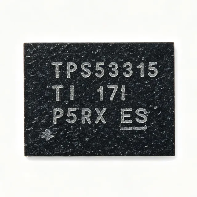
TPS53315 - 12A D-CAP Buck Regulator | Texas Instruments
The Texas Instruments TPS53315 is a D-CAP mode, 12-A synchronous step-down (buck) regulator with integrated MOSFETs, offered in a 5 mm x 7 mm 40-pin VQFN (RGF) package with exposed thermal pad. It supports a supply voltage of 4.5 V to 25 V, conversion input of 3 V to 15 V, and adjustable output from 0.6 V to 5.5 V, targeting ease of use, low external component count, and compact point-of-load power systems. A buck converter is a type of switching DC-DC regulator that efficiently reduces a higher voltage to a lower one. The TPS53315 belongs to the synchronous buck family, using both high-side and low-side MOSFETs for high efficiency, and sits within the broader power management IC hierarchy for point-of-load conversion. Key features include 12-A continuous output current, integrated 19-mOhm high-side and 7-mOhm low-side MOSFETs that minimize conduction losses, an accurate 1% 0.6-V reference, and an integrated boost switch that removes the external bootstrap diode. D-CAP control delivers fast load transient response without external compensation and is stable with ceramic output capacitors. Technically, the proprietary D-CAP architecture combines constant on-time control with adaptive on-time, enabling low output ripple and fast transient behavior. Overcurrent protection, thermal shutdown, and a power-good indicator improve system robustness. The exposed-pad VQFN package provides thermal performance around 25 C/W junction-to-ambient per internal data. Typical applications include point-of-load power for FPGAs, ASICs, and DSPs, as well as server, storage, networking, industrial, and telecom power rails where high efficiency and small size matter. Design tip: use at least 2 x 22 uF ceramic output capacitance for stability and pay careful attention to PCB layout of the power stage and exposed pad for thermal dissipation.

TPS53315 - 12A D-CAP Sync Buck Regulator | Texas Instruments
The Texas Instruments TPS53315 is a D-CAP mode, 12-A synchronous step-down (buck) switching regulator with integrated MOSFETs, housed in a 5 mm x 7 mm 40-pin VQFN package with exposed pad. It is designed for ease of use, low external component count, and compact power systems, with a 0.6 V to 5.5 V adjustable output and single-rail input support. A DC-DC switching regulator (specifically a synchronous buck converter) steps a higher input voltage down to a regulated lower output voltage using integrated power MOSFETs and an external inductor. The D-CAP control topology uses an internally compensated, constant-on-time architecture that eliminates complex external compensation networks and delivers excellent load transient response, placing the TPS53315 high in the power management IC hierarchy: buck converter -> switching regulator -> DC-DC converter -> PMIC. Key features include up to 12 A of continuous output current, one 19-mOhm high-side and one 7-mOhm low-side integrated MOSFET, an accurate 1% 0.6-V voltage reference, and an integrated boost switch for the high-side gate drive. The conversion input voltage range spans 3 V to 15 V, while the supply voltage (VDD) range is 4.5 V to 25 V, allowing a single rail to power both control and conversion stages in many systems. Architecturally, the D-CAP constant-on-time scheme provides near-constant switching frequency with fast transient response and low output ripple, requiring only a small set of external components: input/output capacitors, an inductor, and a feedback divider. This minimizes BOM cost and PCB area compared to traditional voltage-mode controllers with external FETs. Typical applications include point-of-load power for DSPs, FPGAs, and ASICs in networking, telecom, industrial, and computing equipment, where multi-amp core or I/O rails must be generated efficiently from a 5 V or 12 V intermediate bus. It also suits distributed power architectures and dense server memory rails. Design consideration: with 12 A output in a compact VQFN-40 package, PCB thermal design is critical - use generous copper pour on the exposed pad and follow the TI datasheet layout guidelines for the power stage loop to minimize EMI and voltage spikes.
TPS53318DQPR - 8A 22V Sync Buck Converter D-CAP | Texas Instruments
The Texas Instruments TPS53318DQPR is a high-efficiency, 8-A synchronous buck converter with integrated MOSFETs and D-CAP mode control, housed in a 22-pin PowerLFDFN (5 mm x 6 mm) package. It accepts a wide 1.5-V to 22-V conversion input voltage range, delivers an adjustable output down to 0.6 V with 1% reference accuracy, and supports continuous output currents up to 8 A from a compact footprint that suits space-constrained POL rails. A DC-DC switching regulator (also called a buck converter or step-down converter) is a power management IC that converts a higher DC input voltage to a lower DC output voltage with high efficiency by rapidly switching the current path between MOSFETs and smoothing with inductors and capacitors. TPS53318 sits within the larger hierarchy of point-of-load (POL) controllers and voltage regulators used between a system bus (e.g., 12 V or 5 V) and low-voltage digital or analog loads such as ASICs, FPGAs, and DDR memory. The D-CAP mode control eliminates the external compensation network required by voltage-mode and current-mode parts, dramatically reducing BOM count and design effort. Key features include an integrated boost switch (no external bootstrap diode needed in most cases), an Eco-mode for light-load efficiency, programmable soft-start, overcurrent and overtemperature protection, power-good output, and UVLO/OVP. The 22-pin PowerLFDFN package exposes a thermal pad that routes heat directly to inner PCB copper layers, supporting full 8-A continuous operation with proper board layout. Architecturally, TPS53318 uses TI's D-CAP adaptive on-time control with feedback from the output voltage through an internal resistor divider, sampled at the moment the high-side MOSFET turns on. This topology achieves fast transient response without a traditional Type-III compensation network, and the internal low-side synchronous MOSFET removes the need for an external Schottky diode. Typical applications include 12-V to 1.0-V to 3.3-V POL rails powering ASICs, FPGAs, and SoCs; DDR memory VTT termination; 5-V input distributed-bus converters in telecom and server cards; and industrial controllers fed from 24-V nominal rails. The wide 22-V abs-max input also tolerates transients from loosely regulated industrial supplies. When designing in, follow TI's recommended capacitor types (X5R/X7R ceramic with sufficient voltage derating) and ensure the exposed thermal pad has multiple thermal vias to inner copper planes for sustained 8-A operation.
TPS53355DQPR - 30A Sync Buck Converter 1.5-15V | TI
The Texas Instruments TPS53355DQPR is a 30-A D-CAP mode synchronous step-down (buck) converter with integrated 5-mOhm high-side and 2-mOhm low-side MOSFETs, supporting a 1.5-V to 15-V input range and a 0.6-V to 5.5-V adjustable output in a 6-mm x 5-mm, 22-pin QFN (DQP) package. A synchronous buck converter is a DC-DC switching regulator that uses two internally integrated MOSFETs and an external inductor to step a higher input voltage down to a lower, tightly regulated output voltage. Buck regulators form the core of modern point-of-load power management hierarchies, converting intermediate distribution rails (such as 12 V) into the low voltages required by processors, FPGAs, and memory, with far higher efficiency than linear regulators. Key features include the D-CAP control topology, which requires no external compensation network and delivers excellent load transient response, plus TI eco-mode technology that reduces switching frequency at light load to maintain high efficiency across the full load range. The internal 5-mOhm/2-mOhm MOSFET pair minimizes conduction losses at full 30-A output, while the accurate 1% 0.6-V internal reference supports low-voltage core rails. An integrated boost switch eliminates an external bootstrap diode. Technically, the device supports adjustable switching frequency (250 kHz to 1 MHz), adjustable current limit with thermal shutdown protection, and flexible soft-start control. The wide 1.5-V to 15-V conversion input allows direct operation from 12-V intermediate bus rails as well as 5-V and lower rails. Typical applications include server and network processor core power, point-of-load supplies for FPGAs, ASICs, and DDR memory, telecom and datacenter power stages, and distributed power systems where a compact 30-A stage with minimal external components is required. Design consideration: at 30-A output the power stage dissipation is dominated by conduction losses, so a solid PCB thermal layout with generous copper pour on the exposed thermal pad is essential for reliable continuous operation. This page synthesizes distributor availability data, drop-in alternatives, and practical design notes not found in the manufacturer datasheet alone.

TPS53511RGTR - 1.5A Sync Buck Regulator 4.5-18V | TI
The Texas Instruments TPS53511RGTR is a 1.5 A adaptive on-time D-CAP2 mode synchronous step-down (buck) converter with integrated switching MOSFETs, accepting a 4.5 V to 18 V input and delivering an adjustable output down to 0.76 V, housed in a 16-pin VQFN (RGT) package with exposed pad rated from -40C to +85C. A synchronous buck converter is a DC-DC switching regulator that steps a higher input voltage down to a lower output voltage using two internal MOSFETs (high-side and low-side) alternating between input and ground. Compared with a linear regulator, a buck converter achieves high efficiency through switched-mode power conversion, and it sits within the broader hierarchy of power management ICs (PMICs), under voltage regulators and DC-DC converters. Synchronous rectification replaces the external freewheeling diode with a low-side MOSFET, reducing conduction losses. Key features of the TPS53511 include the D-CAP2 control topology, which provides fast transient response with no external compensation components, making the design cost-effective with a low external component count; integrated MOSFETs that eliminate the need for external power switches; and low standby current suited to always-on points-of-load. The adaptive on-time (AOT) architecture dynamically adjusts the switching pulse width against input and output conditions to maintain regulation across load ranges. Technically, D-CAP2 mode combines an internal ripple-generation network with an adaptive on-time scheme, enabling stable operation with small ceramic output capacitors and supporting a wide duty-cycle range for computing power systems. The exposed-pad VQFN-16 (RGT) package provides low thermal impedance to the PCB, and the 4.5 V to 18 V input range covers 5 V, 12 V intermediate bus rails and most AC-DC adapter outputs. Typical applications include points-of-load (POL) regulation in computing power systems, network and communication equipment, consumer electronics, and industrial subsystems requiring a compact, low-component-count 1.5 A buck stage. Cost sensitivity and fast load transients make it a strong fit for memory, SoC core and I/O rails. For design, choose an output capacitor with low ESR to support the D-CAP2 ripple-injection scheme, and verify minimum on-time limits when converting 18 V down to very low outputs. Keep the SW, BOOT and VIN loops tight on the PCB layout. This page synthesizes distributor pricing (as of 2026-09-10), pin-compatible drop-in alternatives including the pin-for-pin TPS54326, and practical design notes not consolidated in the manufacturer datasheet.
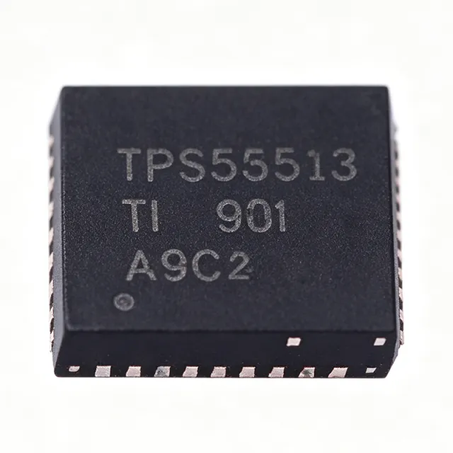
TPS53513RVER - 8A, 18V Sync Buck Converter | Texas Instruments
The Texas Instruments TPS53513RVER is an 8 A synchronous SWIFT step-down (buck) converter with a 1.5 V to 18 V input range, adjustable 0.6 V to 5.5 V output, and an adaptive on-time D-CAP3 control mode, housed in a 28-pin VQFN (RVE) package with exposed pad. A synchronous buck converter is a type of DC-DC switching regulator that steps a higher input voltage down to a lower output voltage using two integrated MOSFETs (a high-side and a low-side switch) instead of an external Schottky diode. Within the power management IC hierarchy, it belongs to the family of switching voltage regulators, which achieve far higher efficiency than linear regulators, making them the standard choice for point-of-load power conversion in digital systems. Key features of the TPS53513 include integrated 13.8-mOhm high-side and 5.9-mOhm low-side MOSFETs delivering 8 A of continuous output current, a precision 600 mV reference with 0.5% tolerance, support for all-ceramic output capacitors, and an integrated boost switch that eliminates one more external component. Technically, the D-CAP3 control topology is an adaptive on-time architecture that provides fast transient response to load steps without complex loop compensation, allowing a very low external-component count. Because switching frequency adapts to input and output conditions, the converter maintains good efficiency across light and heavy loads while supporting high step-down ratios from 18 V rails. Typical applications include powering FPGAs, ASICs, microprocessors, and DSP cores in networking, telecom, industrial, and server equipment, where a compact 8 A point-of-load solution from a 12 V intermediate bus is required. For design, note the device is specified from -40C to +85C ambient; at 8 A loads with 18 V input, thermal design of the exposed-pad PCB land pattern is critical, and all-ceramic output capacitance must be verified against D-CAP3 stability requirements. This page synthesizes distributor pricing, drop-in alternatives, comparison tables, and practical design notes not found in the manufacturer datasheet alone.
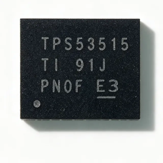
TPS53515RVER - 12A Sync Buck Converter 18V | Texas Instruments
The Texas Instruments TPS53515RVER is a 12 A synchronous SWIFT step-down buck converter with adaptive on-time D-CAP3 control, supporting a 1.5 V to 18 V input range (4.5 V to 25 V bias) and an adjustable 0.6 V to 5.5 V output, housed in a 28-pin VQFN exposed-pad package. It integrates 13.8 mOhm high-side and 5.9 mOhm low-side MOSFETs plus an integrated boost switch for minimal external component count. A buck (step-down) converter is a switching voltage regulator that converts a higher input voltage to a lower regulated output using an inductor, switches, and output capacitors. Within the power-management hierarchy, the TPS53515 sits at the power-management IC level as a fully integrated point-of-load (POL) switching regulator, combining controller and power stage in one package. SWIFT is TI's family name for small-form-factor integrated FET synchronous buck converters used on ASIC, DSP, and FPGA rails. Key features include 12 A continuous output current with high-performance integrated MOSFETs, a 600 mV voltage reference with +/-0.5% tolerance for precise output settings, and D-CAP3 control delivering fast load-step transient response. The device supports all-ceramic output capacitors, eliminating electrolytic capacitors and improving reliability and board height. Integrated internal compensation removes the need for external RC network tuning across the full output range. Technically, the adaptive on-time D-CAP3 architecture varies the on-time with input and output voltage to maintain near-constant switching frequency, providing ease of use and ultra-fast transient response without complex loop compensation. The integrated boost switch drives the high-side MOSFET gate without an external bootstrap diode, and the low on-resistance MOSFETs yield high conversion efficiency at heavy loads. TI's inductor-on-top reference design achieves greater than 87% efficiency with about 2.6 W power loss at 12 A load and 12 mV output ripple using only 10x22 uF ceramic output capacitors. Typical applications include point-of-load supplies for ASICs, DSPs, and FPGAs, network and telecom infrastructure cards, and industrial DC-DC power stages where a compact 12 A solution with minimal external parts is needed. When designing, ensure the bias pin is supplied within its 4.5 V to 25 V range for reliable gate drive, and select the inductor based on the recommended values in the datasheet for stability across the 0.6 V to 5.5 V output range. Forced continuous conduction mode helps meet tight voltage regulation accuracy for performance DSPs and FPGAs. This page synthesizes distributor pricing, drop-in alternatives, comparison data, and practical design notes not found in the manufacturer datasheet.

TPS53622RSBT - VR13 Dual-Channel D-CAP+ Controller | TI
The Texas Instruments TPS53622RSBT is a fully VR13 SVID-compliant dual-channel step-down controller designed for server VCCIO and VMCP rails. It supports 2+0 or 1+1 phase configurations and integrates non-volatile memory (NVM) and a PMBus interface for flexible configuration and telemetry. The device provides two outputs suitable for Intel VR13 processor power delivery, packaged in a 40-pin WQFN (RSB, 5x5 mm) package rated from -40C to 125C. A step-down controller is a power management IC that generates a regulated output voltage lower than its input by driving external power stage MOSFETs. It sits in the voltage regulator hierarchy as the control brain of a multiphase buck converter, converting the 12V server bus into low-voltage core, I/O, and memory rails. The TPS53622 uses D-CAP+ architecture with undershoot reduction (USR), delivering fast transient response, low output capacitance, and good current sharing without external loop compensation. Key features include dual-channel operation in 2+0/1+1 phase configurations, built-in NVM for storing configuration settings, and a PMBus interface for telemetry and control. The controller is fully compatible with TI NexFET power stages such as the CSD95490Q5MC, enabling high-efficiency, highly integrated power conversion solutions with minimal external component count. The TPS53622 integrates SVID logic, allowing direct communication with Intel VR13 processors. Its D-CAP+ control loop provides excellent load transient performance, critical for modern CPUs with rapidly changing current demands. NVM storage reduces boot time and ensures consistent behavior across power cycles, while PMBus enables real-time monitoring of voltage and current for system optimization. Typical applications include server VCCIO and VMCP rails, high-performance computing, data center power delivery, and storage systems. A TI reference design demonstrates 12V input to 1V output at 40A using two CSD95490Q5MC power stages. When designing with the TPS53622, ensure proper layout of the power stage and decoupling capacitors to minimize parasitic inductance, and follow TI's VR13 reference designs for SVID timing compliance.
TPS53624 - Dual-Phase D-CAP+ Buck Controller | Texas Instruments
The Texas Instruments TPS53624 is a dual-phase step-down DC-DC buck controller with integrated gate drivers, packaged in a thermally enhanced, RoHS-compliant 40-pin VQFN (6x6 mm) and rated for operation from -10C to +105C. It targets point-of-load power conversion in servers, storage, networking, and telecom infrastructure. A step-down (buck) controller is a type of switching voltage regulator that converts a higher input voltage to a lower output voltage using MOSFETs, an inductor, and a feedback control loop. Within the power management IC hierarchy, the TPS53624 sits at the controller level - it integrates the control loop and gate drivers but requires external power MOSFETs, giving designers flexibility to scale output current beyond what integrated converters achieve. Key features include the D-CAP+ control architecture, which enables fast transient response with low output capacitance, and OSR (oversampled ripple regulation) for tight regulation with low-ESR output capacitors. The PCNT pin allows selection between dual-phase and single-phase operation, optimizing light-load efficiency versus full-load capability. An integrated 8-bit DAC sets the output voltage digitally, and TI Eco-mode supports high efficiency at light loads. Technically, the dual-phase topology interleaves two switching phases, reducing input and output ripple current, allowing smaller passives, and spreading thermal dissipation across two MOSFET pairs. With integrated drivers, the part eliminates external driver ICs, shortening the gate loop and improving switching behavior. Output voltage, current limit, and switching behavior are programmed via pin straps and the voltage DAC, minimizing external component count. Typical applications include CPU and ASIC core power rails, DDR memory VDDQ supplies, network switch and router POL rails, and distributed 12V bus point-of-load conversion where a controller plus discrete FETs offers the best cost-per-amp. Design tip: keep the gate-drive loops short to the integrated drivers, size the inductor per datasheet recommendations, and use PCNT phase selection deliberately - single-phase saves quiescent power at light loads but doubles per-phase current stress at peak load.

TPS53632 - 3-2-1 Phase D-CAP+ Step-Down Controller | TI
The Texas Instruments TPS53632 is a 3-2-1 phase D-CAP+ step-down driverless controller designed for low-voltage, high-current point-of-load applications. It integrates control logic and gate-drive functions for external power stages in a 32-pin VQFN (4x4 mm) package, eliminating separate driver ICs and reducing BOM count and board area. A step-down (buck) controller is a switching DC-DC converter that regulates a lower output voltage from a higher input rail. Within the power management IC hierarchy, the TPS53632 sits in the voltage regulator > DC-DC converter > multiphase controller family. Its flexible 3-2-1 phase configuration lets designers scale output current while balancing efficiency and thermal performance, and dynamic phase add/drop optimizes light-load efficiency. Key features include the D-CAP+ control architecture, which delivers fast transient response, lowest output capacitance, and high efficiency. The standard I2C Rev 3.0 serial interface enables dynamic output voltage control (dynamic voltage scaling) and current-monitor telemetry for advanced power management. Integrated protection includes overcurrent, overvoltage, and thermal shutdown, supporting robust operation in computing environments. Technically, the driverless architecture pairs the controller with external smart power stages or discrete MOSFETs, giving designers flexibility in current rating and cost. Telemetry via I2C enables real-time load-current reporting, useful for server power capping and health monitoring. Typical applications include server and datacenter VRM power supplies, networking and telecom equipment, storage systems, and high-performance computing core rails (for example, 12V or 5V input down to processor, FPGA, and ASIC core voltages). When designing with the TPS53632, prioritize a clean power-stage layout: keep high-current switching loops short, place decoupling close to the pins, and provide generous copper area for thermal relief. The I2C bus needs pull-up resistors and correct address pin configuration. Pricing varies by distributor, with LCSC listing TPS53632RSMR from about $6.27 as of 2026-08-29.

TPS53632GRSMT - 48V GaN Half-Bridge D-CAP+ Controller | TI
The Texas Instruments TPS53632GRSMT is a half-bridge PWM controller with D-CAP+ architecture, optimized for 48-V GaN-based DC/DC converters in a 32-pin VQFN (RSM) 4x4 mm package with exposed pad. It performs single-stage conversion directly from a 48-V bus, providing fast transient response, minimal output capacitance, and high efficiency. A DC/DC switching controller is a power management IC that regulates output voltage by driving external power switches (here, GaN FETs) through a feedback-controlled PWM loop. Within the power-management hierarchy, the TPS53632G sits in the switching controller family above simple buck converters, targeting LLC-like half-bridge topologies for high-voltage server and telecom power systems. Key features include D-CAP+ control for ultra-fast load transients without complex loop compensation, an I2C Rev 3.0 interface for dynamic output voltage control and current-monitor telemetry, and compatibility with TI GaN power stages for 48-V input conversion. FindIC lists conversion from 2.5 V to 24 V control supply with a step-down single output of 0.5 V to 1.52 V at up to 60 A, making it well suited to low-voltage, high-current CPU/ASIC core rails fed from 48-V infrastructure. Technically, the D-CAP+ architecture combines a constant-on-time modulator with internal ripple compensation, delivering low output ripple and excellent transient behavior even with all-ceramic output capacitor banks. The I2C telemetry loop supports fault status readback, enabling power-system monitoring in datacenter and base-station designs. Typical applications include 48-V server power shelves, GaN-based point-of-load converters, telecom rectifiers, and high-density networking equipment where a single-stage 48-V-to-1-V conversion eliminates an intermediate bus converter stage, improving efficiency and power density. When designing, follow the TI datasheet layout guidelines: keep the switch-node loop compact, place GaN power stages adjacent to the controller, and use the exposed thermal pad soldered to a solid ground plane for heat spreading and EMI control.

TPS53667 - 6-Phase D-CAP+ Buck Controller w/ PMBus | Texas Instruments
The Texas Instruments TPS53667 is a 6-phase, D-CAP+ step-down driverless buck controller with built-in NVM and a PMBus interface, designed for ASIC power and high-current point-of-load applications. It supports 0.5V to 2.5V output via 8-bit BOOT voltage selection with 5 mV steps, and is compatible with NexFET smart power stages such as the CSD9549x and CSD96497Q5MC. The controller is offered in a 40-pin WQFN package (6x6 mm, RTAT suffix) and is characterized for operation over industrial temperature ranges. A buck controller (also known as a step-down controller) belongs to the broader hierarchy of voltage regulator -> DC-DC converter -> power management IC -> semiconductor. Multi-phase buck controllers like the TPS53667 extend single-phase buck topologies by interleaving multiple switching phases to reduce input/output ripple, improve transient response, and distribute thermal dissipation - enabling >100 A core rails from a single controller IC. The TPS53667 is targeted at server, datacenter, and ASIC POL applications where multi-rail digital loads demand precise, programmable, and telemetry-enabled supply voltages. Key features include D-CAP+ modulation for ceramic output capacitor compatibility, PMBus v1.2 system interface for telemetry (VOUT, IOUT, temperature) and programmability (VID, fault thresholds), an internal non-volatile memory (NVM) for storing custom configuration, driverless architecture that drives external NexFET power stages, and on-chip protection including OVP, OCP, and thermal shutdown. The D-CAP+ hysteretic control scheme offers excellent transient response without a traditional compensation network, which simplifies loop design for high di/dt ASIC loads. The 6-phase interleaved operation, combined with PMBus-driven dynamic voltage scaling, makes this controller well-suited for advanced CPU/ASIC cores requiring fast load-step recovery. Typical applications include ASIC/CPU core rails in servers and datacenters, high-current point-of-load regulation for FPGA and SoC platforms, telecom and networking line-card processors, and AI accelerator card POL supplies. Multi-phase interleaving is essential where single-phase solutions would incur excessive ripple or losses. When designing with the TPS53667, pair it with TI's NexFET CSD9549x or CSD96497Q5MC power stages for a fully validated driverless solution. The PMBus address and BOOT voltage are set by external resistor straps, eliminating the need for a separate programming device on the production line.
TPS53681RSBT - Dual 6+2/5+3 D-CAP+ Multiphase Buck Controller | TI
The Texas Instruments TPS53681RSBT is a dual-channel 6+2 or 5+3 phase D-CAP+ multiphase synchronous buck DC-DC controller with PMBus 1.3.1 and on-chip non-volatile memory (NVM), housed in a thermally enhanced 40-pin WQFN (RSB) measuring 5x5 mm. The controller accepts 4.5 V to 17 V input on VCC/VDD supplies, supports a broader PVCC operating range to 28 V for power-stage gate drive, digitally regulates two output rails from 0.25 V up to 5 V, and drives TI NexFET smart power stages to deliver per-rail capability of more than 100 A typical and up to 300 A peak across a -40 C to +125 C junction window. A buck controller is a switch-mode power-supply control IC that drives external MOSFETs or smart power stages to convert a higher DC input into a lower regulated DC output. A multiphase buck controller interleaves multiple converter phases to share load current, reduce input/output ripple, and spread heat across phases. Within the power-management hierarchy, the TPS53681 sits as buck controller -> DC-DC controller -> PMIC -> semiconductor, acting as the digital control brain for high-current VR rails rather than as a stand-alone regulator. Key features include TI D-CAP+ adaptive on-time control that eliminates external RC compensation, full PMBus 1.3.1 compliance with telemetry and fault logging, output margining, adaptive voltage positioning, per-phase current sharing, and integrated NVM that stores user configuration without an external EEPROM. The 5x5 mm WQFN-40 footprint and TI NexFET smart power-stage pin compatibility keep the BOM small while supporting multi-hundred-ampere rails. The dual-channel architecture can be configured as 6+2 or 5+3 phases to support asymmetric CPU and GPU rails with independent VID tables. The D-CAP+ control loop uses internal ripple injection and adaptive on-time, removing the compensation network required by traditional peak-current-mode controllers. Combined with TI NexFET smart power stages, the TPS53681 achieves high efficiency from sub-ampere sleep states to multi-hundred-ampere peak loads while integrating precision current sharing and per-phase fault protection. PMBus provides VID programming, output margining, and on-the-fly telemetry of VOUT, IOUT, temperature, and fault status for closed-loop platform management. Typical applications include server and high-end desktop CPU core VRs supporting Intel VR13 and AMD SVI2 protocols, DDR4 and DDR5 memory VTT termination, workstation CPU and GPU power, base-station DSP and FPGA core rails, and PCIe auxiliary power. PMBus telemetry also makes it well suited to data-center PSUs and infrastructure platforms that require remote monitoring across the full operating temperature range. When designing with this part, place decoupling capacitors within 2 mm of each PVCC and VCIN pin and follow TI NexFET layout guidelines for gate-drive return paths. Always configure NVM defaults using Fusion Digital Power Designer GUI before production ramp; mismatched PMBus addresses on parallel controllers can cause SMBus arbitration failures at start-up. This page synthesizes distributor pricing, drop-in alternatives, and practical design notes not found in the manufacturer datasheet alone.
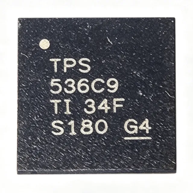
TPS536C9RSLR - Dual-Channel 12-Phase D-CAP+ Controller | TI
The Texas Instruments TPS536C9RSLR is a dual-channel, up to 12-phase step-down digital multiphase D-CAP+ controller with Intel VR14 SVID and PMBus interfaces, packaged in a thermally enhanced 48-pin VQFN (RSL) measuring 6x6 mm. It is designed for high-current, low-voltage CPU and ASIC core power conversion in servers, datacenter, and high-performance computing platforms. A multiphase buck controller is a switching-voltage-regulator controller that interleaves multiple power stages, sharing current across phases to distribute thermal load, reduce input and output ripple, and enable very fast transient response. Multiphase controllers sit at the top of the power management hierarchy, orchestrating NexFET power stages that each integrate driver and FET functions. Key features include the D-CAP+ control architecture with undershoot reduction (USR) and overshoot reduction (OSR) for fast transient response with low output capacitance; built-in non-volatile memory (NVM) for configuration storage; full PMBus command support for telemetry and control; and Intel VR14 SVID compliance for direct communication with Intel processors. The two channels (N + M) can be flexibly phase-assigned up to 12 total phases, supporting dual-rail designs such as VCORE plus VSOC. The device is fully compatible with TI NexFET power stages (such as the CSD and TPS power-stage families), enabling a complete controller-plus-power-stage solution with differential remote voltage sensing and per-phase current balance. Digital loop control provides programmable transient behavior and startup sequencing without external compensation components. Typical applications include Intel server CPU core rails (VR14), AI accelerator and GPU core power, high-current ASIC and FPGA point-of-load conversion, and storage or networking processor supplies. Design consideration: the controller requires configuration via NVM programming (TI Fusion Digital Power Designer) and careful layout of the differential remote sense lines and current-sense routing to the power stages; follow the TI datasheet layout guidelines for SW, VOSNS, and CS pins to achieve specified transient accuracy.

TPS536C9T - Dual-Channel 12-Phase D-CAP+ Controller | TI
The Texas Instruments TPS536C9T is a dual-channel (N + M <= 12 phase) D-CAP+ step-down multiphase buck controller with TLVR (trans-inductor voltage regulator) topology support, PMBus, and VR14 SVID interfaces, housed in a 48-pin VQFN (RSL) package measuring 6.00 mm x 6.00 mm with exposed pad. It operates from a 4.5 V to 17 V input range and regulates outputs down to 0.25 V, supporting up to 765 A total output current when paired with TI smart power stages. A multiphase buck controller is a power management IC that distributes a high-current step-down conversion across several interleaved phases, reducing input/output ripple, spreading thermal load, and improving transient response compared with a single-phase regulator. In the power management hierarchy, the TPS536C9T sits at the controller layer: it drives external smart power stages rather than integrating FETs, enabling server-class current levels far beyond what monolithic converters achieve. Key features include the D-CAP+ control architecture for fast transient response, low output capacitance, and strong dynamic current sharing; native TLVR support for modern CPU load-transient profiles; an integrated non-volatile memory (NVM) for pin-free configuration; and compliance with the Intel VR14 SVID specification alongside a full PMBus interface for telemetry, fault management, and runtime adjustment. Technically, the digital controller loops monitor per-phase current and temperature, and firmware-configurable parameters (stored in NVM) define phase count, switching behavior, and protection thresholds such as overcurrent, overvoltage, and overtemperature. The device is fully compatible with TI smart power stages (e.g., CSD95xxx family), simplifying design-in for multi-rail server and accelerator boards. Typical applications include VR14-compliant CPU core power for servers and workstations, ASIC/FPGA accelerator rails, high-current point-of-load conversion in networking and datacenter equipment, and 12-phase TLVR evaluation platforms such as the TPS536C7EVM-051. Design tip: because TLVR coupling and layout strongly affect transient performance, follow the TI layout guidelines for the SYNC/RESET and current-sense pins, and verify SVID boot sequencing against the platform's VR14 requirements.
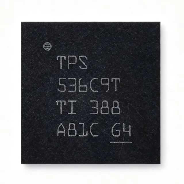
TPS536C9TRSLR - 12-Phase TLVR Buck Controller, 765A | TI
The Texas Instruments TPS536C9TRSLR is a dual-channel (N + M <= 12 phase) D-CAP+ step-down multiphase switching controller supporting up to 765A total output current in a thermally enhanced 48-pin VQFN (RSL) package with exposed pad. It supports input voltages from 4.5V to 17V and output voltages from 0.25V to 5.5V. A multiphase buck controller is a power-management IC that orchestrates multiple power stages in parallel to deliver high current at low voltage, dividing current among phases for reduced ripple, better thermal distribution, and fast transient response. The TPS536C9T sits within the hierarchy of switching regulators as a controller-class device, pairing with external TI NexFET smart power stages to form a complete voltage regulator solution (VR) for processors. Key features include native trans-inductor voltage regulator (TLVR) topology support with LC open and short protection, VR14 SVID interface compliance, and a PMBus interface for telemetry and configuration. Built-in non-volatile memory (NVM) stores configuration, and the D-CAP+ architecture provides fast transient response, low output capacitance, and accurate dynamic current sharing across phases. The controller is fully compatible with TI NexFET smart power stages, allowing flexible N+M phase allocation (N+M <= 12, M <= 6) between the two channels. This scalability suits both compact dual-rail designs and high-current single-rail configurations used by modern server CPUs and GPUs. Typical applications include server CPU core power (VR14 SVID rails), ASIC and FPGA point-of-load power, AI accelerator power delivery, and networking line-card processors requiring sub-1V, multi-hundred-amp rails with PMBus manageability. Design tip: TI recommends keeping at least 800 mil distance between controller and power stages, sharing a common ground plane, and using the PMBus/NVM configuration flow during bring-up to tune loop response before production. This page synthesizes verified datasheet parameters, drop-in alternatives, and practical design guidance not found on the manufacturer product page.
TPS53915RVER - 12A Sync Buck D-CAP3 Regulator | TI
The Texas Instruments TPS53915RVER is a 12-A synchronous step-down (buck) switching regulator with an adaptive on-time D-CAP3 control mode, supplied in a 28-pin VQFN package with exposed thermal pad. It operates from a 1.5-V to 18-V input (4.5-V to 25-V bias) and produces an adjustable 0.6-V to 5.5-V output with 0.5% reference accuracy. A synchronous buck converter is a DC/DC switching regulator that uses two internal MOSFETs plus an inductor to step a higher input voltage down to a lower, well-regulated output. Within the power management hierarchy (regulator -> switching regulator -> SWIFT point-of-load converter), buck converters deliver high efficiency compared to linear regulators because power is transferred through inductive switching rather than dissipated as heat. Key features include integrated 13.8-mOhm high-side and 5.9-mOhm low-side MOSFETs supporting 12-A continuous output current, PMBus-based configuration of voltage margining, soft-start time, power-on delay, VDD UVLO level and fault reporting, and an integrated boost switch for the high-side gate drive. The D-CAP3 adaptive on-time topology provides fast transient response with very low external component count, simplifying layouts in space-conscious systems. Technically, the TPS53915 is trimmed at the factory to enable PMBus commands with a default switching frequency of 400 kHz. The device uses a current-consuming strategy for stability with low-ESR ceramic output capacitors and supports a wide duty cycle range, making it flexible across 5-V, 12-V and intermediate bus rails down to sub-1-V core voltages. Typical applications include point-of-load power for DSPs, FPGAs and ASICs, industrial and enterprise server power rails, and telecom/datacom 12-V distributed power systems requiring fast transient response and high current density. Design tip: ensure adequate PCB copper area on the exposed pad for heat dissipation at full 12-A load, and verify PMBus resistor straps or serial configuration choices against datasheet sequencing guidance before layout. Pricing shown is as of 2026-08-29.