Amplifier ICs
بەرهەمەکان (3,200+)

TS3704CD - Quad Micropower CMOS Comparator | STMicroelectronics
The STMicroelectronics TS3704CD is a four-channel micropower CMOS voltage comparator with push-pull outputs, supplied in a 14-pin SOIC package. It is designed for low-power signal conditioning and is identified by the manufacturer as an obsolete part. The device accepts a 3 V nominal supply according to distributor product records, operates from 0°C to 70°C in the standard TS3704CD grade, and uses a 35 uA typical comparator current as listed for the closely matched TLC3704CD family. A voltage comparator is an analog integrated circuit that compares an input voltage with a reference voltage and changes its digital output state when the relationship between the two signals changes. The TS3704CD belongs to the comparator hierarchy: analog mixed-signal IC, voltage comparator, quad comparator, and power-management signal-conditioning IC. Four independent channels in one package can reduce board area and simplify designs requiring several threshold-detection or overvoltage-monitoring functions. The TS3704CD uses CMOS circuitry to limit consumption and a push-pull output stage to eliminate the external pull-up resistor normally required with open-collector comparators. The four channels share a common supply arrangement within the package, while each comparator provides its own non-inverting and inverting inputs and logic output. This makes the device applicable to threshold crossings, sensor interfaces, signal conditioning, and general-purpose digital logic interfaces. According to the manufacturer datasheet, the TS3704 is a micropower quad CMOS voltage comparator whose typical current is approximately 9 uA per comparator, while the identified TLC3704 comparison records state 35 uA. Push-pull outputs can drive CMOS-compatible loads directly and transition without the passive pull-up network associated with open-drain comparators. Designers should still check output current, supply voltage, input common-mode range, and output levels for each operating condition before reuse. Typical uses include battery-powered monitoring, industrial control thresholds, sensor signal conditioning, window comparison, and four-channel level detection. The 14-SO package is suitable for conventional through-hole assembly and prototype boards. Because TS3704CD is obsolete, engineers should use a qualified drop-in option when possible or confirm lifecycle, availability, and qualification requirements for long-term production programs. For a new PCB, preserve the 14-pin SOIC footprint and verify every signal against the replacement part's pin description. Pay particular attention to input common-mode range, propagation delay, output polarity, supply voltage, and input bias current, since a matching package alone does not guarantee equivalent behavior in every operating condition. This page consolidates lifecycle information, verified distributor records, pin-compatible migration options, comparison parameters, and practical replacement guidance. The structured alternatives help engineers move away from the obsolete TS3704CD without relying on a mechanically similar but electrically unsuitable part.

TS3704CN - Micropower Quad CMOS Comparator | STMicroelectronics
The STMicroelectronics TS3704CN is a micropower quad CMOS voltage comparator with four independent comparison channels, push-pull outputs, and a low typical supply current of 9 µA per comparator. The device is packaged in a 14-pin DIP and is designed for low-power threshold detection, signal conditioning, and voltage-level comparison. A voltage comparator is an analog semiconductor that compares an input voltage with a reference or threshold and changes its output when the relationship between those voltages changes. The TS3704 belongs to the comparator hierarchy within integrated circuits and analog signal conditioning. Compared with the bipolar LM339 family, its CMOS implementation consumes substantially less current and uses push-pull outputs, eliminating the external pull-up resistor normally required by open-collector comparators. The principal features of the TS3704CN include four CMOS comparator channels, 9 µA typical current consumption per comparator, a fast response time of 2 µs typical for a 5 mV overdrive, and typical input impedance of 10^12 ohms. Its push-pull output stage can drive logic inputs directly while reducing external component count. The device is also described as pin-to-pin and functionally compatible with the bipolar LM339, although output polarity, common-mode limits, supply behavior, and timing should still be checked before substitution. The TS3704 architecture supports four independent threshold or window-detection functions in one package. High input impedance reduces loading on high-impedance sensor nodes, while the low 9 µA typical consumption per comparator suits battery-operated equipment. The 2 µs typical response is useful for systems requiring fast decisions without moving to a higher-power comparator family. Its through-hole DIP-14 construction also favors legacy industrial, instrumentation, and educational designs where socketed or leaded assembly is preferred. Typical uses include battery-powered sensor interfaces, overvoltage and undervoltage detection, industrial control thresholds, window comparators, and low-power monitoring systems. The TS3704CN is particularly appropriate when one board requires several independent comparisons and when avoiding open-collector pull-up components materially simplifies the design. Designers should account for input common-mode range, supply voltage, output drive, and input overvoltage before assigning comparator inputs. Because this is a leaded DIP device, board spacing, soldering heat, and cleaning practices also affect long-term assembly reliability. Decoupling should follow the manufacturer datasheet guidance, especially when long PCB traces or switching sources are present. This product record combines the manufacturer datasheet, distributor identification, explicit package information, cross-reference candidates, and practical engineering guidance to support component selection, replacement assessment, PCB planning, and low-power comparator design.
TS3704IN - 4-Channel Micropower CMOS Comparator | STMicroelectronics
The STMicroelectronics TS3704IN is a micropower quad CMOS voltage comparator with four independent comparison channels, push-pull outputs, and a 14-pin PDIP package. Each comparator typically consumes 9 µA, while the complete device is designed for low-power signal conditioning. According to the manufacturer datasheet, the TS3704IN supports input voltages up to ±8 V with a nominal 16 V supply and accepts a single supply from 3 V. A voltage comparator is an analog integrated circuit that compares two input voltages and changes its digital output state when one input exceeds the other. This places the TS3704IN within the hierarchy of comparator IC, analog interface IC, and semiconductor. Four independent channels in one package reduce board area in threshold detection, window comparison, sensor conditioning, and control systems where several voltage relationships must be monitored. Key features include a push-pull CMOS output stage that eliminates the external pull-up resistor required by open-collector comparators. The typical input offset voltage is 5 mV, typical input bias current is 600 pA, and the response time is approximately 2 µs for a 5 mV overdrive. A nominal supply voltage of 3 V and an operating temperature range from -40 °C to +125 °C support both portable and industrial designs. The CMOS input stage provides high input impedance, helping the TS3704IN interface with high-impedance sensors without drawing substantial signal current. Its four-channel architecture also simplifies power sequencing because all comparators operate from the same supply. The push-pull output can actively drive both high and low states, although designers must account for the output current and voltage limits specified by the manufacturer when connecting loads. Typical uses include battery-powered threshold detection, industrial sensor interfaces, window comparators, overvoltage monitoring, control-system logic, and four-channel signal conditioning. In portable equipment, the 9 µA typical consumption per comparator is especially useful. For longer trace runs or noisy industrial environments, input filtering and careful grounding remain necessary even though the push-pull output reduces dependence on external pull-up hardware. PCB layout should keep input and output traces short, provide a stable ground reference, and place input filtering close to the comparator inputs. Because all four channels share supply pins, bypassing the supply close to the package helps minimize disturbance between channels. Avoid relying on the comparator output for functions requiring a pull-up resistor, since the TS3704IN output architecture is push-pull rather than open collector. This product page combines the manufacturer’s electrical characteristics, package and pin information, verified distributor listings, application guidance, and a strictly same-package alternative assessment. It is intended to help engineers determine whether the TS3704IN’s four channels, low current consumption, input impedance, and output architecture fit a specific low-power design.

TS372CD - Dual Precision CMOS Comparator | STMicroelectronics
STMicroelectronics TS372CD is a low-power dual precision CMOS voltage comparator containing two independent differential comparators, with a response time of 600 ns, a single-supply operating range of 1.5 V to 8 V, and an 8-pin SOIC package. Each comparator provides CMOS, MOS, or TTL-compatible open-drain output operation for interfacing with mixed logic systems. A voltage comparator is an analog signal-processing IC that compares an input voltage against a reference voltage and changes its output state when the differential input crosses the switching threshold. A dual comparator integrates two independent channels into one package. Within the broader semiconductor hierarchy, TS372CD belongs to the comparator and amplifier IC family, where it bridges low-power analog sensing and digital logic control. The TS372CD emphasizes low power and precision. The manufacturer specifies a very low supply current of 0.1 mA per comparator, independent of supply voltage. Its extremely low input bias current is typically 1 pA, and its input offset current is also typically 1 pA. These characteristics reduce disturbance from high-impedance sensors and make the device suitable for monitoring systems where the source impedance could otherwise create input-related errors. Its differential CMOS architecture supports single-supply or dual-supply operation. The wide single-supply range extends from 1.5 V to 8 V, while the dual-supply capability covers positive and negative sensing ranges. The open-drain outputs require an external pull-up resistor when the output must rise to a positive logic voltage. This configuration provides flexible bus-level interfacing and permits wired-AND behavior when multiple outputs share a pull-up node. Typical uses include battery-powered threshold detection, sensor signal conditioning, window monitoring, overvoltage and undervoltage detection, and low-speed control loops. The 600 ns response time is appropriate for power-management, industrial-control, and instrumentation systems that require a rapid decision without the higher energy consumption of a high-speed comparator. Design the pull-up network around the required logic level, output rise time, and total capacitance. Place the pull-up resistor close to the output net, keep comparator input traces away from switching nodes, and account for input bias current when driving very high source impedances. Verify startup behavior and logic thresholds across temperature when the comparator controls a safety-critical or precision system. This product page combines the TS372CD electrical characteristics, package details, verified drop-in replacement information, comparison parameters, and practical interface guidance. It helps engineers evaluate whether its low-power precision architecture fits a design before checking the manufacturer datasheet and confirming application-specific limits.

TS372CN - Dual CMOS Comparator, 8-DIP | STMicroelectronics
The STMicroelectronics TS372CN is a low-power dual CMOS voltage comparator with two independent comparison channels, a 1.5 V to 8 V single-supply operating range, support for dual supplies up to ±8 V, and an 8-DIP package. It produces open-drain, TTL-compatible outputs and combines very low supply current with extremely low input bias current. A voltage comparator is an analog integrated circuit that compares two input voltages and changes its output state when the difference crosses a reference level. Comparators belong to the broader interface and signal-conditioning hierarchy, where they convert physical voltage relationships into logic-level events. The TS372CN’s dual-channel architecture provides independent decisions within one package, reducing board area compared with two separate single comparators. Key characteristics include supply current of 0.1 mA per comparator independent of supply voltage, input bias current of 1 pA typical, and input offset current of 1 pA typical. The device operates from a 1.5 V to 8 V single supply or from dual supplies within the stated ±8 V limit. Its open-drain outputs can support TTL-compatible interfacing, while the low-power operation is useful when continuously powered sensing is required. The CMOS input stage is suited to monitoring high-impedance sources because the extremely low bias current minimizes loading of the measured node. Each comparator can evaluate an input against a reference voltage or against the other input when configured as a differential comparator. The manufacturer datasheet should be consulted for the complete electrical characteristics, input common-mode limits, output sink-current limits, and propagation-delay curves. Typical applications include battery-powered threshold detection, sensor-condition interfaces, window comparators, overvoltage and undervoltage indication, low-level signal crossings, and general dual-threshold logic. Two independent channels can also implement hysteresis, zero-cross detection, or a pair of complementary limit checks without requiring two separate IC packages. Designers should account for the open-drain output architecture by providing a pull-up resistor at every output used with subsequent digital logic. Input common-mode voltage, output timing, and supply bypass requirements must remain within the manufacturer’s specified operating limits. Decoupling capacitance should be placed close to the supply pins, while sensitive input traces should be kept short and away from switching nodes. This page organizes the key electrical characteristics, commercial information, package details, application guidance, and available cross-reference information for engineers evaluating the TS372CN. It also highlights where a substitution requires direct pin and parameter verification rather than relying on package similarity alone.
TS372ID - Dual CMOS Voltage Comparator, 8-SOIC | STMicroelectronics
The STMicroelectronics TS372ID is a low-power dual CMOS voltage comparator in an 8-pin SOIC package. It contains two independent precision differential comparators designed for single-supply operation from 3 V to 16 V or dual-supply operation from plus or minus 1.5 V to plus or minus 8 V. Each comparator offers an open-drain output suitable for TTL-compatible interfacing. A voltage comparator is an analog integrated circuit that compares two input voltages and produces a digital logic state indicating which input is higher. The TS372ID belongs to the comparator category within analog and mixed-signal integrated circuits, where it is used for threshold detection, level sensing, signal conditioning, and simple control decisions. Its dual architecture allows two independent comparisons in one package, reducing component count when two threshold functions are required. The TS372ID uses STMicroelectronics silicon linMOS technology and emphasizes low power consumption. The manufacturer specifies a very low supply current of 0.1 mA per comparator, independent of supply voltage. Its extremely low input bias current is typically 1 pA, and its input offset current is also typically 1 pA, making the device suitable for high-impedance sensing circuits where source leakage could otherwise change the decision point. The wide operating-supply range allows the same device family to support low-voltage single-rail systems or balanced dual rails. Because the outputs are open-drain, each output requires an external pull-up resistor. This arrangement supports wired logic functions and allows the output transition speed to be adjusted through the pull-up resistance and circuit capacitance, but it also means an external pull-up is required to obtain a valid high output state. Typical uses include battery-powered threshold detection, sensor signal conditioning, overvoltage and undervoltage monitoring, window-comparison functions, and low-power control logic. When two comparators operate from the same supply, their individual input, output, and supply pins still require careful routing to avoid unintended coupling or output contention. For layout, place input and output traces away from high-current switching nodes and preserve a short return path to the supply ground. Select pull-up resistors according to the required rise time and available output current, and ensure that the input common-mode range remains within the limits stated in the manufacturer datasheet for the selected supply voltage. Decoupling capacitors should be placed close to the supply pins, with the ground connection kept short. This page organizes the TS372ID supply, input-current, package, output, and application information into an engineering-oriented selection guide. It also documents where to find the official datasheet, how to interpret the package and pinout, what to verify before making a replacement, and how to request a quotation through the XAIPART Request a Quote form.
TS372IN - Dual CMOS Voltage Comparator, 8-DIP | STMicroelectronics
The STMicroelectronics TS372IN is a low-power dual CMOS voltage comparator containing two independent precision comparators, with a 600 ns response time and a maximum input offset voltage of 12 mV. Housed in an 8-pin through-hole DIP package, it accepts single supplies from 3 V to 16 V or dual supplies from ±1.5 V to ±8 V. Each comparator consumes approximately 0.1 mA, making the device suitable for low-power signal-conditioning systems. A voltage comparator is an analog mixed-signal semiconductor that compares two input voltages and produces a digital-level indication of their relationship. The TS372IN belongs to the comparator hierarchy and uses CMOS input stages with open-drain outputs, allowing its outputs to support TTL-compatible interfacing. Two independent comparator channels in one package reduce component count when a system needs two sensing or threshold decisions. Key features include independent comparator operation, low supply current of 0.1 mA per comparator, and operation from either a single or dual supply. The single-supply range of 3 V to 16 V supports industrial logic systems, while the ±1.5 V to ±8 V dual-supply range permits comparison of signals around ground. The open-drain output architecture also enables wired-AND behavior when multiple comparator outputs share a pull-up resistor. The differential CMOS architecture provides a favorable balance between speed, power consumption, and input behavior. With a response time of 600 ns, the TS372IN is suitable for threshold monitoring, signal crossing detection, and control-loop qualification without the delay of slower micropower comparators. Its two independent channels can monitor separate sensor nodes or provide complementary decisions, although common-mode range and input-bias details should be checked against the manufacturer datasheet for the exact operating conditions. Typical applications include industrial sensor thresholding, battery and power-supply monitoring, overvoltage detection, window comparison in control systems, and low-power logic interfaces. The device can also participate in line-driver or receiver designs where open-drain outputs are pulled up to a suitable logic supply. In dual-supply systems, it is useful when signals may fall below ground or rise above a midpoint reference. Design the input network so the differential signal remains within the comparator’s specified common-mode operating range, especially when operating from a 3 V single supply. Place the pull-up resistor directly at each open-drain output and confirm that its value produces the intended rise time. Do not permit an output to exceed its supply voltage, and use the DIP footprint without relying on exposed-pad thermal dissipation because the package does not provide one. This product page combines supply-range and timing details with package-level engineering guidance, application analysis, and qualified same-footprint replacement information. It is intended to help engineers select the TS372IN, plan the input and output network, and assess drop-in alternatives without confusing package compatibility with guaranteed functional equivalence.
TS374CD - Low-Power Quad CMOS Comparator | STMicroelectronics
The STMicroelectronics TS374CD is a low-power quad differential CMOS voltage comparator containing four independent precision comparator channels in a 14-pin SOIC package. The device supports single- or dual-supply operation, provides open-drain outputs compatible with CMOS, MOS, and TTL logic, and combines a typical response time of 200 ns with very low power consumption. Its four-channel arrangement allows one package to implement four independent sensing or threshold functions. A voltage comparator is an analog semiconductor that compares two input voltages and changes its output state when the difference crosses a defined threshold. The TS374CD belongs to the comparator hierarchy within analog and interface ICs. Each channel has differential inputs, high input impedance, and an open-drain output that can pull a logic node low. When used with a pull-up resistor, the open-drain architecture supports wired logic, level translation, and direct interfacing with multiple open-drain devices. The principal device characteristics include four independent channels, a typical input impedance of 10^12 ohms, a typical input bias current of 1 pA at 5 V, and a maximum quiescent current of 250 microamperes. The fast typical response time of 200 ns is useful for signal crossing, threshold detection, and control-loop applications where the comparator must react quickly after an input differential changes polarity. Open-drain outputs provide flexible system integration without driving the output high actively. The TS374CD uses four independent precision voltage comparators implemented with STMicroelectronics silicon linear MOS technology. This process is intended to provide a favorable balance between consumption and operating speed. The very high input impedance reduces loading on the signals being measured, while the low typical bias current is beneficial when the comparator monitors high-impedance sensors or threshold networks. Because the output is open drain, its rising voltage is established by an external pull-up resistor rather than an internal active pull-up. Typical applications include sensor-threshold detection, overvoltage and undervoltage monitoring, window comparison, zero-cross detection, industrial control logic, and general-purpose analog signal conditioning. Four channels can also be used as independent comparator elements in a compact design, reducing package count compared with discrete or single-channel implementations. A pull-up resistor should be selected according to the target logic family, bus capacitance, and required rise time. When designing with the TS374CD, account for open-drain behavior and provide a suitable pull-up on every output used by downstream logic. Review input common-mode limits, supply range, output sink current, and propagation timing in the manufacturer datasheet before setting thresholds. Because this ordering code is listed as obsolete, confirm lifecycle status and obtain an approved replacement or a supported availability plan before beginning a new production design. This product page organizes the TS374CD’s comparator architecture, electrical characteristics, practical applications, verified equivalent information, and design considerations. It also highlights the lifecycle constraint and distinguishes a documented cross-brand alternative from components that may use the same 14-pin footprint but differ in output behavior, supply limits, or logic compatibility.
TS374ID Low-Power Quad Comparator | STMicroelectronics
The STMicroelectronics TS374ID is a low-power quad differential voltage comparator containing four independent comparison channels, a 3 V to 16 V supply range, open-drain outputs, and a 14-pin SOIC package. It provides a typical response time of 200 ns and a typical input impedance of 10^12 ohm, making it suitable for precision threshold, sensing, and signal-conditioning circuits. A voltage comparator is an analog signal-conditioning integrated circuit that compares two input voltages and changes its output state when the difference crosses a defined threshold. The TS374ID belongs to the comparator hierarchy, within analog ICs and signal-conditioning semiconductors. Its four channels can perform independent comparisons while sharing one supply and ground connection, reducing component count in multi-channel monitoring designs. Key characteristics include four independent differential comparators, low-power CMOS operation, low input offset voltage, a 3 V to 16 V operating range, and open-drain outputs. The open-drain architecture allows each output to be pulled up to the required logic level with an external resistor, which is useful when interfacing the TS374ID to systems operating above or below its supply voltage. The TS374ID uses STMicroelectronics silicon linear MOS technology to achieve its consumption-to-speed balance. Its typical 200 ns response time supports faster threshold decisions than general-purpose slow comparators, while the high typical input impedance reduces loading on the sensed source. Each differential input pair provides a non-inverting and an inverting comparison input, and the output indicates which input is higher. Typical uses include sensor threshold detection, battery and power-supply monitoring, industrial control logic, window comparators, overvoltage detection, and general digital control interfaces. The quad configuration is particularly useful when a board must monitor several independent analog quantities, such as temperature, pressure, current, or supply rails. Designers should use pull-up resistors on all open-drain outputs and confirm that output rise time, input common-mode range, and supply timing meet the system requirements. Care is also needed when several comparators can pull an output low simultaneously, because the shared pull-up resistor must tolerate the combined sink current. This page combines the TS374ID electrical characteristics, package details, practical circuit considerations, and package-compatible replacement guidance to support faster component selection, footprint verification, and second-source planning.
TS374IDT - Low-Power Quad CMOS Comparator | STMicroelectronics
The STMicroelectronics TS374IDT is a low-power quad CMOS voltage comparator with four independent comparison channels, an open-drain output, and operation from a single 3 V to 16 V supply or from dual supplies of ±1.5 V to ±8 V. The device is packaged in a 14-pin SOIC and is intended for low-power voltage-sensing, threshold-detection, and signal-conditioning systems. A voltage comparator is an analog integrated circuit that compares two input voltages and changes its output state when their relationship crosses a defined threshold. The TS374 belongs to the comparator hierarchy within analog and interface semiconductors. Its four-channel architecture allows one package to monitor four independent signals, reducing board area when several sensing or control functions are required. The TS374IDT features very low supply current of approximately 0.1 mA per comparator, independent of supply voltage, and extremely low input bias and input offset currents of approximately 1 pA typical. The input offset voltage is specified to a maximum of 12 mV, while the response time reaches 600 ns. Its CMOS input stage supports operation from a single supply or from positive and negative dual supplies. Each channel uses open-drain output structure, allowing the output to be pulled up to a suitable external voltage and permitting wired connection to a shared bus when only one channel should actively assert a logic state. The open-drain architecture also provides flexibility when interfacing with CMOS, MOS, or TTL-compatible downstream circuitry. The manufacturer lists the TS374 family as a low-power quad CMOS voltage comparator supporting supply ranges from 3 V to 16 V or ±1.5 V to ±8 V. Typical uses include battery-powered threshold detection, industrial sensor interfaces, window or level monitoring, overvoltage detection, control systems, and general-purpose signal conditioning. The low input current is especially useful with high-impedance sensors because it minimizes loading of the measured signal. Designers should account for input common-mode limits, output pull-up requirements, input offset voltage, and the effect of supply noise on comparison accuracy. Every open-drain output needs an appropriate pull-up resistor unless it is intentionally connected to a shared wired-AND node. Decoupling close to the supply pins remains important even though the device itself consumes very little current. This product page combines manufacturer electrical characteristics, package details, sourcing information, and application guidance. It also highlights the design trade-offs involved when using a quad open-drain comparator instead of single-channel or push-pull alternatives, helping engineers select the correct replacement without changing the PCB footprint.
TS374IN - Low-Power Quad CMOS Comparator | STMicroelectronics
STMicroelectronics TS374IN is a low-power quad CMOS voltage comparator containing four independent precision differential comparators, with a 200 ns typical response time, 10^12 ohm typical input impedance, and a 14-DIP package. The device accepts single- or dual-supply operation and provides open-drain, CMOS, MOS, or TTL-compatible output interfacing. A voltage comparator is an analog semiconductor that evaluates two input voltages and changes its output state when one input crosses the other. Quad comparators integrate four independent channels into one package, providing efficient threshold detection, window monitoring, and signal conditioning. Within the electronics hierarchy, the TS374IN belongs to the comparator family of analog and mixed-signal ICs, where precision voltage sensing interfaces with digital control systems. The TS374IN provides four independent precision channels in one 14-DIP package. Its input impedance of 10^12 ohms typical minimizes loading on high-impedance sensor and divider networks. A 200 ns typical response time supports faster decision-making in monitoring and control circuits, while the open-drain output architecture permits wired logic, pull-up integration, and multi-node signal combinations. The STMicroelectronics silicon lin MOS process gives the device its low-power operating characteristics and favorable consumption-speed ratio. Each comparator can operate from single or dual supplies, allowing the TS374IN to suit low-voltage logic systems as well as broader analog interfaces. Open-drain outputs support CMOS, MOS, and TTL-compatible downstream logic when suitable pull-up devices are used. Typical uses include four-channel threshold monitoring, sensor-signal conditioning, overvoltage detection, window comparators, industrial control interfaces, and general digital logic interfaces. The high input impedance is especially useful when the comparator must observe a high-impedance divider or sensor without materially affecting its operating point. The 14-DIP through-hole package also simplifies prototype construction and legacy PCB maintenance. When using open-drain outputs, include the appropriate pull-up resistor on each channel and account for its effect on rise time. Common-mode voltage limits, supply voltage, and output sink-current requirements must also be checked against the circuit operating conditions. The TS374IN datasheet pin description should be used directly when assigning PCB connections. This product data combines the STMicroelectronics family description with package, interface, and electrical characteristics, then adds application guidance, pin-use cautions, and a structured comparison framework to support practical design decisions.

TS391ILT - Low-Power Single Comparator | STMicroelectronics
The STMicroelectronics TS391ILT is a low-power, single voltage comparator with a supply range of 2 V to 34 V, a response time of approximately 0.3 µs to 1.3 µs depending on the operating condition, and an open-collector output. The device is packaged in a 5-pin SOT-23 surface-mount package for compact analog signal-conditioning and threshold-detection circuits. A voltage comparator is an analog integrated circuit that compares two input voltages and produces a digital output indicating which input is higher. The TS391 belongs to the comparator hierarchy within analog and mixed-signal semiconductors. Its low-power design makes it useful where continuous monitoring is required, including industrial control, sensor interfaces, power-supply sequencing, battery monitoring, and portable equipment. Key characteristics include very low supply-current consumption, low input bias current, low input-offset voltage, and an input common-mode range extending close to both supply rails. Operation from a single supply is supported, and split-supply operation is also possible. The open-collector output requires an external pull-up resistor and can be connected to a compatible logic supply when the open-drain node must rise above the comparator supply voltage. The TS391/TS391A family uses an open-collector output architecture rather than a push-pull output. This allows the output to be pulled up to a selected logic voltage, supports wired-AND behavior with suitable arrangements, and provides a defined state when the output transistor is off. Input bias and offset characteristics determine the practical switching threshold accuracy, while propagation delay determines how quickly the circuit responds to an input crossing. Typical uses include monitoring sensor outputs, detecting overvoltage or undervoltage conditions, comparing temperature-derived analog signals, and providing a simple control decision in battery-powered products. The SOT-23-5 format supports dense PCB layouts, although engineers should account for the package's limited thermal dissipation and the output pull-up component required by the open-collector architecture. For reliable operation, use the pin-description table in the manufacturer datasheet when assigning PCB tracks because the comparator uses a specific five-terminal SOT-23 layout. Confirm input voltage, common-mode range, output pull-up voltage, and propagation-delay limits across the complete temperature range before committing the circuit to a safety- or timing-sensitive application. This product overview consolidates the comparator's electrical limits, package details, replacement constraints, and practical design guidance into one engineering reference. It also distinguishes true pin-compatible alternatives from functionally similar devices with different pin assignments, helping prevent PCB rework and unintended board-level failures.
TS393CN - Micropower Dual CMOS Comparator | STMicroelectronics
The STMicroelectronics TS393CN is a micropower dual CMOS voltage comparator featuring two independent comparison channels, open-drain outputs, and a typical supply current of 9 µA per comparator. It is packaged in an 8-pin DIP and is designed as a micropower alternative to the bipolar LM393. Its input impedance is typically 10^12 ohms, while its typical response time is 2.5 µs with 5 mV overdrive. These characteristics make the TS393CN suitable for low-power threshold detection, signal conditioning, and sensing circuits where dual-channel comparison is useful. A voltage comparator is a type of analog interface IC that compares two input voltages and produces a digital logic result indicating which input is higher. In this product hierarchy, the TS393CN is a dual-channel comparator, belonging to the broader comparator and analog interface IC families. Each channel can monitor a sensor, measurement node, or control threshold independently, allowing one package to perform two related comparison functions while consuming only 9 µA typically per channel. The TS393CN offers high input impedance of 10^12 ohms typically, minimizing loading on the circuit being measured. Its 2.5 µs typical response time for 5 mV overdrive provides useful speed for threshold-control applications while retaining the low current consumption associated with CMOS design. Open-drain outputs also support wired-AND, wired-OR, and level-shifting arrangements when suitable pull-up resistors are added. The manufacturer identifies the device as pin-to-pin and functionally compatible with the bipolar LM393. Because both channels are implemented in CMOS, the TS393CN avoids the comparatively high quiescent current of conventional bipolar LM393 implementations. The manufacturer describes its typical consumption as 20 times lower than the bipolar LM393 while retaining similar performance. This makes it particularly attractive in battery-operated equipment where the comparator can remain active continuously without imposing the same continuous bias-current burden as a bipolar counterpart. Typical uses include battery threshold monitoring, window-comparison systems, temperature-limit detection, low-voltage signaling, and general-purpose sensing interfaces. The two independent channels can compare two sensed quantities against separate references or implement complementary threshold decisions. Its 8-pin DIP format also supports through-hole prototyping, educational equipment, repair work, and industrial control assemblies where socketed or leaded components are preferred. Designers should account for the open-drain output architecture by placing a pull-up resistor on each output. Input common-mode range, supply-voltage limits, output sink current, and operating temperature boundaries must be checked against the manufacturer datasheet before final circuit release. The DIP package also requires adequate lead spacing and mechanical clearance from nearby conductors, especially in high-voltage or densely populated assemblies. This page combines the core electrical characteristics of the TS393CN with package information, practical comparator design guidance, and a focused comparison with documented LM393-compatible devices. It is intended to help engineers identify where the micropower CMOS implementation offers a practical advantage without overlooking the open-drain pull-up requirements and application-specific limits of the original design.
TS393IN - 2-Channel 9 uA CMOS Comparator | STMicroelectronics
The STMicroelectronics TS393IN is a micropower dual CMOS voltage comparator with two independent comparison channels, a typical supply current of 9 uA per comparator, and a typical response time of 2.5 us in an 8-pin DIP package. It provides an open-drain output configuration and is designed as a low-power alternative to the conventional bipolar LM393. A voltage comparator is an analog integrated circuit that compares two input voltages and changes its output state when the non-inverting input rises above the inverting input, or conversely. Within the broader semiconductor hierarchy, the TS393IN belongs to the comparator and amplifier IC class, supporting signal conditioning, threshold detection, sensing, and control applications. Its CMOS construction combines low bias current with high input impedance, helping preserve weak sensor signals. Key features include extremely high input impedance of 10^12 ohms typical, low typical consumption of 9 uA per comparator, and a response time of 2.5 us typical. The device is compatible with bipolar LM393 applications while offering CMOS input behavior. Two independent channels allow simultaneous comparisons or the implementation of window-comparator and independent threshold-detection functions within one package. The open-drain outputs require an external pull-up resistor when the output must reach a defined logic-high voltage. This arrangement supports wired-open-drain logic, level translation, and system designs in which several devices share a bus, provided the pull-up voltage and sink-current limits are checked. Each comparator can also operate in the standard comparator configuration, with one input serving as the threshold and the other accepting the sensed signal. Typical uses include battery-powered sensor interfaces, low-voltage threshold detection, industrial control logic, monitoring systems, and compact embedded equipment. The TS393IN is particularly useful when the signal source has high source impedance and conventional bipolar comparators would load the input. Its low power consumption also benefits longer-running battery systems, although total system current should include pull-up resistors and external circuitry. For PCB layout, place the pull-up resistors close to the open-drain output nets and keep sensitive input traces away from switching nodes and high-current return paths. Confirm the absolute maximum supply voltage, input common-mode range, output sink current, and input protection limits against the manufacturer datasheet before applying either input beyond the recommended operating range. This product page combines the TS393IN electrical characteristics, pin assignment, package information, practical comparator design guidance, application examples, and drop-in replacement analysis to support faster component selection and board-level implementation.
TS393MD - Micropower Dual CMOS Comparator | STMicroelectronics
The STMicroelectronics TS393MD is a micropower dual CMOS voltage comparator with two independent comparison channels, open-drain outputs, and an 8-pin SOIC package. Each channel consumes 9 uA typically, has a typical input impedance of 10^12 ohm, and provides a typical response time of 2.5 us. The device is designed for low-power sensing and control circuits requiring high input impedance. A voltage comparator is an analog integrated circuit that compares an input voltage against a reference voltage and changes its output state when the relationship between those voltages changes. Comparators are used within analog signal chains, embedded control systems, and power management equipment. The TS393 belongs to the comparator family, the amplifier and analog IC hierarchy, and ultimately the broader integrated-circuit and semiconductor categories. The TS393MD provides two CMOS comparator channels in one package, reducing component count in dual-threshold or dual-signal systems. Its open-drain outputs permit wired-AND behavior when suitable pull-up resistors are installed. High input impedance minimizes loading of the sensed source, while the 2.5 us typical response time supports applications that need meaningful response speed without the continuous power demand of a faster bipolar comparator. The 9 uA typical supply current per comparator makes the device suitable for battery-operated instruments, portable monitors, and low-power sensor interfaces. STMicroelectronics describes the TS393 as compatible with the bipolar LM393 architecture, which can simplify comparison with conventional dual-comparator designs. The manufacturer also offers the similar TS3702 as a push-pull-output alternative, although its output topology is not interchangeable with the TS393MD open-drain interface without circuit changes. Typical uses include battery-powered threshold detection, sensor signal conditioning, industrial control inputs, and low-power monitoring systems. In each case, the two channels can monitor independent quantities or provide complementary decisions around a reference voltage. The TS393MD is also suitable where the source impedance is high and the comparator should avoid materially loading the monitored node. Designers should account for the open-drain output when selecting pull-up voltage and resistance. Input common-mode limits, supply-voltage range, offset behavior over temperature, and output sink-current capability must be checked in the manufacturer datasheet before finalizing a circuit. PCB placement should keep the comparator input paths short and away from high-current switching nodes to reduce noise coupling. This page combines the manufacturer device description, distributor package information, practical application guidance, and verified drop-in replacement information. It also identifies the measurable differences among directly compatible SOIC-8 options, helping engineers compare output type, supply current, temperature range, and qualification requirements before making a board-level replacement.
TS393MDT - Micropower Dual Comparator | STMicroelectronics
The STMicroelectronics TS393MDT is a micropower dual CMOS voltage comparator with two independent comparison channels, typically consuming 9 µA per comparator. The device accepts supply voltages up to 18 V, provides an input impedance of 10^12 Ω typical, and achieves a typical response time of 2.5 µs. It is packaged for surface-mount assembly in an 8-pin SOIC package, with the MDT ordering code identifying STMicroelectronics’ temperature-grade and delivery configuration. A voltage comparator is an analog integrated circuit that compares an input voltage against a reference voltage and changes its output state when the relationship between them changes. The TS393MDT belongs to the comparator hierarchy within amplifier and signal-conditioning integrated circuits. Its dual-channel architecture allows two independent threshold decisions in one package, while its CMOS input stage provides very high impedance and draws minimal supply current for battery-powered and always-on equipment. Key features include open-drain outputs, which permit wired-OR connection and operation with external pull-up resistors. The manufacturer describes the TS393 as compatible with the bipolar LM393 function while consuming approximately 20 times less current than the dual bipolar LM393. Its operating temperature range extends from -55 °C to 125 °C, making it suitable for industrial, automotive, and defense-related equipment when the complete system design and qualification requirements are satisfied. The electrical characteristics support threshold sensing where low supply current, high input impedance, and moderate propagation speed are more important than nanosecond response. A 10^12 Ω typical input impedance minimizes loading of high-impedance sensor nodes, while the 2.5 µs typical response time allows the device to respond to slowly changing or moderate-frequency events. The open-drain architecture requires a pull-up resistor when a logic-high output is required, and careful attention should be paid to output-node capacitance, leakage, and pull-up resistor selection. Typical applications include battery-powered monitoring circuits, industrial sensor interfaces, dual-threshold detection, window comparators, overvoltage and undervoltage supervision, and logic-level conversion between open-drain nodes. Two comparators in one package are especially useful when a compact design must monitor one signal against two limits or perform complementary decisions. When laying out a board, place input and pull-up components close to the relevant pins, maintain a stable ground reference, and avoid long traces around high-impedance input nodes. Because the output is open drain, the effective rise time depends on the pull-up resistance and total output capacitance rather than solely on the comparator’s internal response time. This product page combines the TS393MDT electrical characteristics, practical comparator design guidance, sourcing information, and a clearly qualified drop-in comparison with the bipolar LM393DT. It supports faster component selection by separating verified device facts from application-specific design considerations and replacement trade-offs.
TS507CD - 1.9MHz Precision Rail-to-Rail Op Amp | STMicroelectronics
The STMicroelectronics TS507CD is a single-circuit, high-precision operational amplifier with rail-to-rail input and output operation, a 1.9 MHz gain-bandwidth product, and an 8-SOIC package. It is designed for general-purpose precision signal conditioning and supports stable operation across its supply-voltage range. An operational amplifier is a voltage-feedback amplifier used to amplify, buffer, filter, or compare small analog signals. The TS507 belongs to the operational-amplifier hierarchy within analog ICs and broader semiconductor signal-conditioning systems. Its rail-to-rail input stage accepts signals close to the supply rails, while the rail-to-rail output stage provides useful output swing near both limits. The TS507CD uses precision trimming to achieve low input-offset voltage without external zeroing. Its listed maximum input-offset voltage is 550 µV, and its typical common-mode rejection ratio is 115 dB. A 1.9 MHz gain-bandwidth product supports general-purpose closed-loop operation, while the low 850 µA supply current suits low-power analog systems. The device is specified as a single general-purpose amplifier in an 8-SOIC package. Its operating temperature range is listed as 0°C to 85°C, and its typical output-current capability is 128 mA. These characteristics make it appropriate for precision sensor interfaces, active filters, signal buffers, and portable equipment where low offset and low supply current are more important than high bandwidth. Typical uses include bridge-sensor amplification, transducer-signal conditioning, low-frequency active filters, and buffered analog measurements. Because the amplifier operates rail-to-rail at the input and output, system designers can use more of the available supply range, but common-mode and output-swing limits still require verification under the intended load and supply conditions. When laying out a TS507CD circuit, keep feedback components and the input source connections short, and route high-impedance inputs away from switching nodes. Decoupling capacitors should be placed close to the supply and ground pins. Confirm gain-bandwidth, output-swing, and stability requirements against the actual gain, load, supply voltage, and operating temperature. This page combines the TS507CD device description, package information, application guidance, comparison parameters, and verified sourcing references to help engineers evaluate the amplifier and identify technically suitable alternatives before PCB release.
TS507ID - Low-Offset Rail-to-Rail Op Amp | STMicroelectronics
The STMicroelectronics TS507ID is a single-circuit, general-purpose operational amplifier in an 8-pin SOIC package. It is designed around rail-to-rail input and output operation, allowing the amplifier to operate close to the supply rails in precision analog signal chains. The TS507 uses a new trimming technique that produces very low offset voltage without requiring external zeroing, reducing assembly time and eliminating the need for a trim potentiometer in precision measurement circuits. A rail-to-rail operational amplifier is an amplifier whose input common-mode range and output swing extend close to both supply-voltage limits. This capability is valuable when the signal being amplified operates near a positive or negative rail and a conventional amplifier would saturate. The TS507 therefore suits precision instrumentation, sensor interfaces, low-level signal conditioning, and measurement systems where usable signal range is more important than absolute isolation from the rails. The TS507ID is identified by DigiKey and Mouser as a standard, general-purpose instrumentation amplifier section in an 8-SOIC package. Its trimmed internal design targets stable electrical characteristics across the operating range and very low offset without external adjustment. For designs requiring tighter control of input bias current, offset drift, noise, bandwidth, supply current, or temperature range, consult the manufacturer datasheet and select the appropriate TS507 grade and package variant. Because the TS507ID accepts both positive and negative signal inputs and supports near-rail output swing, it can serve as the active element in difference amplifiers, current-to-voltage converters, bridge-sensor front ends, and precision feedback networks. The 8-pin SOIC footprint also allows it to be placed in the same general layout class as many standard single op amps, although engineers should verify the actual pin assignment and stability requirements before substituting another device. When designing with the TS507ID, begin by defining the signal amplitude, common-mode range, required output swing, source impedance, and noise gain. Check the datasheet for the operating voltage range, unity-gain bandwidth, slew rate, input bias current, offset voltage, noise density, and stability conditions. Place the feedback components close to the amplifier, keep sensitive input nodes away from switching-current paths, and use a ground layout that minimizes voltage drops across analog return currents. This page combines manufacturer-level product information, verified distributor listings, package and pin-assignment guidance, application analysis, and drop-in replacement guidance. It also distinguishes confirmed package-compatible TS507 family variants from options that require additional electrical verification, helping engineers narrow a redesign quickly before committing a new component to a PCB.
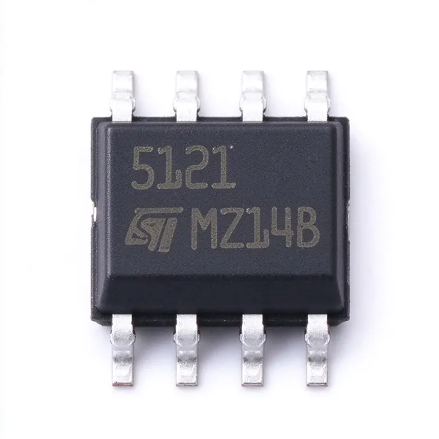
TS512ID - 3 MHz Precision Dual Op Amp | STMicroelectronics
The STMicroelectronics TS512ID is a precision dual operational amplifier with two independent amplifiers, a 3 MHz gain-bandwidth product, and a maximum input offset voltage of 500 µV. The device is supplied in an 8-pin SOIC package and operates from single or dual power supplies, making it suitable for signal-conditioning and instrumentation applications requiring two amplifiers in one package. An operational amplifier is an analog integrated circuit that uses very high open-loop gain to amplify the difference between its inverting and non-inverting inputs. Precision operational amplifiers are a subtype of voltage-feedback amplifiers characterized by low offset voltage, low distortion, low noise, and stable operation with feedback. The dual-amplifier configuration places two amplifiers in one package, reducing board area and simplifying paired signal-processing circuits. The TS512 family provides a 3 MHz gain-bandwidth product, low input offset voltage of 500 µV maximum, low power consumption, short-circuit protection, low distortion, low noise, high channel separation, and internal ESD protection. According to the STMicroelectronics family datasheet, the minimum slew rate is 0.8 V/µs for TS512 and TS512A. The related TS512B has a guaranteed higher minimum slew rate of 1.072 V/µs. The TS512 family uses internal frequency and phase compensation to support stable operation in voltage-follower configurations. This is useful in application circuits where one amplifier buffers a source and the other performs gain or filtering. Its dual supply range is ±1.5 V to ±15 V, while single-supply operation is supported from 3 V to 30 V, allowing use in both conventional analog circuits and higher-voltage industrial interfaces. Typical uses include sensor-signal conditioning, low-level instrumentation, active filtering, audio preamplification, and general analog signal processing. The dual channel can implement matched buffer, gain, summing, or differential stages. Because offset voltage influences accuracy near the zero-voltage operating point, input-source resistance and bias-current compensation should be evaluated carefully. PCB layout should keep input and feedback paths short and place input compensation or filtering components close to the relevant amplifier pins. Both channels should share stable supply decoupling, while avoiding current paths through analog ground that carry output or digital return current. The SOIC package is suitable for conventional surface-mount assembly and conventional thermal design at low to moderate output current. This page consolidates the verified manufacturer-family information, distributor listing details, package data, sourcing information, and engineering guidance for TS512ID. It distinguishes documented TS512-family characteristics from unavailable detailed electrical limits and clearly identifies uncertainty where the supplied source data does not provide a defensible value.
TS512IDT - 3MHz Dual Precision Op Amp | STMicroelectronics
STMicroelectronics TS512IDT is a dual precision operational amplifier with a 3 MHz gain-bandwidth product, 8 nV/√Hz input-voltage noise density, and 0.03% distortion, housed in an 8-pin SOIC package. The TS512x family combines internally compensated low-noise operation with stable voltage-follower performance, making each amplifier suitable for precision signal conditioning and audio paths. An operational amplifier, or op amp, is a high-gain differential amplifier that uses external feedback to set gain and filtering behavior. In the electronics hierarchy, the TS512IDT is a precision operational amplifier within the broader amplifier IC and analog signal-processing categories. Its two independent channels allow one package to process two signals, while internal frequency and phase compensation simplify voltage-follower and other high-gain configurations without external compensation components. The principal features include 3 MHz gain-bandwidth product, 8 nV/√Hz noise density, 0.03% distortion, low power consumption, short-circuit protection, and high channel separation. Operation from a single 3 V to 30 V supply or from dual ±1.5 V to ±15 V rails gives designers flexibility across industrial, instrumentation, and signal-conditioning systems. The low-noise and low-distortion characteristics are particularly relevant when small sensor and audio signals must be amplified without adding substantial broadband noise or harmonic distortion. Internally compensated architecture supports stable operation in voltage-follower configurations despite the amplifier's relatively high gain-bandwidth product. The TS512x family is designed for general-purpose precision applications where clean signal amplification matters more than very high speed. Two channels in one package reduce board-area requirements, while high channel separation helps maintain signal integrity when the channels process related low-level signals. The amplifier also includes ESD protection and a macromodel for circuit simulation. Typical uses include audio preamplification, instrumentation-amplifier input stages, active filters, sensor signal conditioning, transducers, and general-purpose analog measurement chains. The 8-pin SOIC package is useful where conventional surface-mount assembly is required and the circuit operates across the stated -40°C to +125°C temperature range. The wide supply-voltage range also permits operation from industrial rails while retaining compatibility with lower-voltage analog systems. Designers should verify input and output voltage limits, common-mode range, output-swing behavior, and stability against the exact load connected to each channel. Decoupling capacitors should be placed close to the supply pins, while sensitive-input routing should avoid nearby switching nodes and high-current return paths. The dual package does not require matched channels for general use, but input bias-current and offset behavior must be considered in precision DC measurements. This page combines the TS512IDT's principal electrical characteristics with pin-compatible family alternatives, application guidance, comparison parameters, and practical circuit-design notes. These engineering-focused details help shorten component evaluation and support a more reliable transition from initial schematic design through PCB implementation and production qualification.
TS512IN - 3MHz Dual Precision Op Amp | STMicroelectronics
The STMicroelectronics TS512IN is a precision dual operational amplifier with a 3 MHz gain-bandwidth product, 1.5 V/µs slew rate, and a maximum input offset voltage of 500 µV, supplied in an 8-pin Mini DIP package. It is designed for general-purpose instrumentation, analog signal conditioning, and dual-channel measurement applications where two amplifiers share the same package. A dual operational amplifier is an analog integrated circuit containing two independent amplifier channels. Operational amplifiers are voltage amplifiers whose behavior depends mainly on external feedback components. The TS512IN combines frequency-compensated amplifiers for stable voltage-follower operation, low distortion, low noise, short-circuit protection, and internal ESD protection. The 3 MHz gain-bandwidth product supports useful closed-loop bandwidth well below 3 MHz at higher noise gains, while the 1.5 V/µs slew rate improves response to larger transient signals. A maximum offset voltage of 500 µV helps reduce DC error in precision feedback networks. Its dual-channel organization reduces package count and simplifies PCB routing when two amplified signals must be processed under shared supply conditions. The device operates from single 6 V to dual ±15 V supplies, matching conventional analog and industrial voltage ranges. Internal phase compensation allows voltage-follower use without an external compensation network. Short-circuit protection limits the effects of output overload, although sustained shorts still require appropriate supply and thermal checks. Internal ESD protection improves handling robustness without eliminating the need for normal assembly precautions. TS512IN applications include sensor-interface amplification, low-frequency instrumentation, dual audio-channel control, buffering, active filtering, and general analog signal conditioning. Designers should place input and feedback components close to their associated pins, observe the specified common-mode and output-current limits, and avoid excessive loading near the bandwidth and slew-rate limits. This product page combines verified manufacturer-linked specifications, source URLs, package information, application guidance, and honest comparison limitations. It distinguishes confirmed TS512IN attributes from parameters that require verification before a PCB or production cross-reference is approved.
TS514ID - High-Speed Precision Quad Op Amp | STMicroelectronics
STMicroelectronics TS514ID is a high-speed, precision quad operational amplifier with four amplifier circuits, internally compensated frequency and phase response, short-circuit protection, internal ESD protection, and a 14-pin SOIC package. The verified product data identifies a maximum offset voltage of 500 uV and highlights a high gain-bandwidth product, low distortion, low noise, low power consumption, and high channel separation. The TS514ID is intended for instrumentation and general-purpose precision signal-processing designs requiring four amplifiers in one package. An operational amplifier, commonly called an op amp, is a voltage-controlled differential amplifier with very high open-loop gain. Its external feedback network determines the closed-loop behavior. The TS514 belongs to the operational-amplifier hierarchy, which includes instrumentation amplifiers, buffer amplifiers, comparators, and general-purpose voltage amplifiers. Internal phase compensation allows the TS514 to operate as a voltage follower despite its high gain-bandwidth product, reducing the external compensation effort required in many designs. The quad architecture integrates four amplifier channels into one 14-pin SOIC-14 package. Verified manufacturer-related product descriptions identify low offset voltage, low power consumption, short-circuit protection, low distortion, low noise, high gain-bandwidth product, high channel separation, and internal ESD protection. These characteristics make the device applicable to precision buffering, signal conditioning, instrumentation, industrial measurement, and general analog signal-processing systems. Each amplifier requires stable supply decoupling and careful handling of output-current limits. The TS514 uses internal frequency and phase compensation. This architecture is particularly useful in follower and precision-gain configurations because the compensation is already incorporated into the device. Its high speed does not eliminate the need for short feedback traces, adequate grounding, and supply bypassing. Designers should avoid long output routing and place input, output, and ground returns so that parasitic capacitance does not degrade stability or transient response. Typical uses include four-channel sensor conditioning, low-level signal amplification, active filtering, voltage buffering, and instrumentation chains requiring several matched amplifier functions. Industrial control and test equipment can also use the quad package to reduce board area compared with four discrete single-amplifier packages. Where precision offset and noise dominate, the complete manufacturer datasheet should be consulted for test conditions and application-specific limits. The principal design trade-off is speed versus power and stability margin. Although the TS514 supports high-speed operation and voltage-follower use, board layout, capacitive loading, output-current demand, and supply bypassing remain critical. A short, low-inductance layout with local decoupling is recommended. Application notes and the manufacturer datasheet should control the final compensation, grounding, and thermal implementation. This product page combines verified distributor and datasheet information with practical guidance on precision analog design, package reuse, selection criteria, and drop-in alternatives. It also distinguishes confirmed TS514-family candidates from cross-package or merely functional substitutes so engineers can avoid redesigns that require PCB changes.
TS514IN - Quad Precision Op Amp | STMicroelectronics | DIP-14
The STMicroelectronics TS514IN is a high-performance quad operational amplifier with internal frequency and phase compensation, supplied in a 14-DIP package. The device contains four amplifier channels in one package and is designed for general-purpose instrumentation, signal-conditioning, and analog control applications where stable voltage-follower operation is useful. The verified manufacturer description identifies low offset voltage, low power consumption, short-circuit protection, low distortion, low noise, high gain-bandwidth product, high channel separation, and internal ESD protection as key features. An operational amplifier is an analog integrated circuit that amplifies the voltage difference between its inverting and non-inverting inputs. A quad operational amplifier extends this architecture to four independent channels in one package, reducing board area and simplifying multi-channel designs. The TS514IN belongs to the broader operational-amplifier, analog-amplifier, signal-conditioning, and semiconductor hierarchy. The TS514IN's compensated architecture is intended to support stable operation as a voltage follower despite its high gain-bandwidth product. Internal compensation simplifies circuit design when unity-gain stability is required, while short-circuit protection improves robustness in conventional analog signal paths. Low offset voltage supports precision-oriented instrumentation, and low noise and low distortion are useful for audio and measurement front ends. Four channels make the device suitable for sensor signal conditioning, current-voltage conversion, active filtering, waveform shaping, instrumentation amplifiers, feedback networks, and general analog control loops. The 14-DIP package is appropriate for through-hole prototyping, educational systems, laboratory instruments, and industrial assemblies where a dual-inline footprint is preferred over a fine-pitch surface-mount package. The principal design consideration is to verify the supply-voltage limits, input common-mode range, output swing, input bias current, noise density, and load-current behavior against the manufacturer datasheet before finalizing a new design. Decoupling capacitors should be placed close to the supply pins, and unused amplifier inputs should be tied to a defined voltage within the input common-mode range. This page consolidates the verified manufacturer and distributor information, package details, application guidance, technical limitations, and drop-in replacement analysis. It also identifies parameters that require confirmation from the complete TS514 datasheet rather than substituting unverified assumptions.
TS522ID - Dual 15MHz Low-Noise Op Amp | STMicroelectronics
The STMicroelectronics TS522ID is a monolithic dual operational amplifier optimized for precision audio signal processing. It provides two amplifiers, a 15 MHz gain-bandwidth product, a 7 V/µs slew rate, low-voltage noise of 4.5 nV/√Hz, and a maximum input offset voltage of 850 µV in an 8-pin SOIC package. The device operates from 5 V to 30 V over an industrial temperature range of -40°C to +125°C. An operational amplifier is a voltage-controlled differential amplifier that uses feedback to amplify the difference between two input voltages. The dual configuration places two amplifiers in one package, allowing stereo audio, balanced signal paths, active filtering, or independent measurement channels to share a common footprint. Within the broader semiconductor hierarchy, the TS522 belongs to the operational-amplifier family, the analog amplifier category, and the signal-conditioning IC hierarchy. The TS522 combines low input offset, low voltage noise, and high dynamic performance for audio-oriented designs. Its 850 µV maximum input offset voltage supports accurate signal amplification, while the 4.5 nV/√Hz voltage-noise density is particularly relevant when processing low-level microphone, musical-instrument, or line-level signals. A 15 MHz gain-bandwidth product provides useful bandwidth for audio and general-purpose precision applications, and the 7 V/µs slew rate improves large-signal response. Internally, each amplifier is configured around high-gain stages with internal ESD protection. The manufacturer datasheet reports low distortion of 0.002%, macromodel inclusion, and excellent frequency stability. These characteristics make the TS522 suitable for precision audio signal chains where low noise, low distortion, and predictable frequency response matter more than very low power consumption. Typical uses include stereo audio preamplification, active crossover filters, mixer input stages, microphone preamplifiers, audio buffer circuits, and low-level sensor-conditioning channels. Two amplifiers in the same 8-pin SOIC package can reduce board area in stereo designs, while the industrial temperature range supports industrial control, communications, and instrumentation equipment. Designers should verify the required supply headroom, input common-mode range, output swing, noise gain, and stability for the selected feedback network. Decoupling capacitors should be placed close to the supply pins, and sensitive audio inputs should use short traces with suitable grounding to minimize parasitic pickup. A SPICE macromodel is available for circuit simulation, but board-level stability and distortion should still be verified with real components. This page consolidates the verified TS522ID operating characteristics, sourcing links, application guidance, design cautions, and replacement information. It also distinguishes confirmed technical facts from parameters that were not present in the supplied source data, helping engineers make a defensible design decision without treating unverified values as guaranteed specifications.