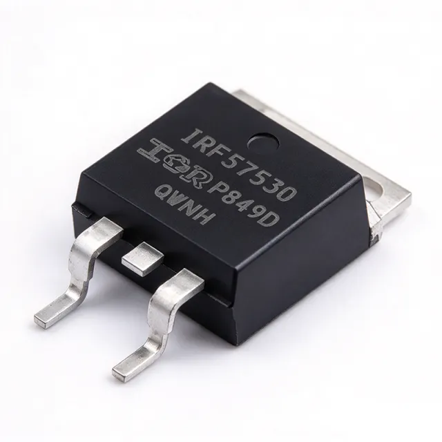
IRFS7530TRLPBF - 60V N-Ch StrongIRFET 2mΩ 195A D2PAK | Infineon
Teilenummer: IRFS7530TRLPBF ✓ Aktiv| Menge | Stückpreis | Gesamt |
|---|---|---|
| 1 | $3.12 | $3,12 |
| 10 | $2.84 | $28,40 |
| 100 | $2.31 | $231,00 |
| 500 | $1.96 | $980,00 |
| 1.000 | $1.72 | $1.720,00 |
IRFS7530TRLPBF Übersicht
A power MOSFET is a voltage-controlled semiconductor switch that modulates current flow between drain and source terminals when a sufficient gate-source voltage is applied. Within the broader hierarchy, MOSFETs belong to the transistor family, the discrete-semiconductor category, and finally the power-management ecosystem of a system. N-channel enhancement-mode MOSFETs like the IRFS7530TRLPBF are the workhorses of high-current switching because their majority carriers (electrons) deliver lower RDS(on) for a given silicon area than P-channel counterparts.
Key features include an avalanche-rated body diode for unclamped inductive switching ruggedness, a logic-level-compatible gate threshold, and a low thermal resistance package that enables direct attachment to a PCB copper pour or external heatsink. The 2 mΩ RDS(on) minimizes conduction losses, while the 60 V rating gives ample headroom for 12 V and 24 V automotive/industrial rails. StrongIRFET™ process technology trades absolute lowest figure-of-merit for better avalanche energy, EMI behavior, and dv/dt immunity than competing trench MOSFETs.
Architecturally, the device uses a trench-gate structure that increases channel density per unit area, driving down RDS(on) without inflating gate charge. Typical gate charge is in the low-nanocoulomb range, supporting switching frequencies suitable for synchronous rectification, hot-swap, and e-fuse applications. The combination of low Qg and low RDS(on) yields an excellent Figure-of-Merit (FOM = RDS(on) × Qg), which directly correlates to converter efficiency at a given switching frequency.
Typical applications include high-current synchronous rectification in 12 V buck converters, OR-ing and hot-swap controllers for telecom and server power distribution, motor-drive H-bridges, battery protection and load switches in e-mobility, and industrial 24 V bus systems. The automotive-grade-compatible variant (IRFS7530-7PPBF) is commonly sourced where AEC-Q101 qualification is mandatory.
When designing with this part, verify safe operating area (SOA) for pulsed load conditions, ensure the gate drive voltage fully enhances the device (typically 10 V VGS), and provide sufficient PCB copper or an external heatsink to keep Tj below 150 °C. The D2PAK package simplifies heatsink attachment via the exposed drain tab, which is electrically connected to pin 2.
Drop-in-Alternativen für IRFS7530TRLPBF – gleiches Gehäuse, Pin-kompatibel. Bauteile mit anderem Gehäuse, die eine PCB-Überarbeitung erfordern, sind ausgeschlossen.
Schnellvergleichstool – Wählen Sie Alternativbauteile für den Direktvergleich:
IRFB7534PBF
✓ Auf Lager
$1.85 / Stück
Datenblatt ansehen →IRF5210PBF
✓ Auf Lager
$0.8203 / Stück
Datenblatt ansehen →IPB027N10N3GATMA1
✓ Auf Lager
$1.62 / Stück
Datenblatt ansehen →BSC009NE2LS5IATMA1
✓ Auf Lager
$1.02 / Stück
Datenblatt ansehen →IRFS7530PBF
📋 Referenzalternative (nicht im Katalog)
IRFS7434TRLPBF
📋 Referenzalternative (nicht im Katalog)
IRFS7530TRLPBF Grenzwerte & elektrische Eigenschaften
| Manufacturer | Infineon Technologies |
| Part Number | IRFS7530TRLPBF |
| Technology | StrongIRFET™ (N-Channel Trench MOSFET) |
| Drain-Source Voltage (VDS) Max | 60 V |
| Continuous Drain Current (ID) at Tc=25°C | 195 A |
| On-Resistance RDS(on) Max @ VGS=10V | 2 mΩ |
| Total Power Dissipation (PD) at Tc=25°C | 375 W |
| Betriebstemperaturbereich | -55 °C to +175 °C (Tj) |
| Gehäuse / Bauform | PG-TO263-2 (D2PAK, TO-263) |
| Montageart | Surface Mount |
| Packaging | Tape & Reel (TR) |
| Lead-Free / RoHS | Yes (PBF suffix) |
| Pin Configuration | 3-Pin (Gate, Drain tab, Source) |
| Series | StrongIRFET™ |
IRFS7530TRLPBF Pin-Konfiguration
| Pin 1 | Gate (G) — Gate drive input - apply VGS ≥ 10V to fully enhance the device |
| Pin 2 | Drain (D) / Tab — Drain terminal, electrically and thermally connected to the exposed metal tab |
| Pin 3 | Source (S) — Source terminal - reference for gate drive and Kelvin connection |
Sicherer Arbeitsbereich - DC
Typische Anwendungen
IRFS7530TRLPBF ist geeignet für 6 Anwendungs: 12V Synchronous Rectification in Buck Converters, Automotive Battery Switch and Load Disconnect, Hot-Swap and OR-ing in Telecom Power Distribution, Motor Drive H-Bridge and Half-Bridge, Industrial 24V Bus Power Switching, Solar MPPT and Battery Management.
12V Synchronous Rectification in Buck Converters
The IRFS7530TRLPBF is well suited as the low-side synchronous rectifier in 12 V buck converters powering CPUs, GPUs, and ASICs. Its 60 V VDS rating provides 5× margin over a nominal 12 V rail plus transient overshoot, while the 2 mΩ RDS(on) minimizes conduction loss in the low-side FET during the freewheeling phase. The StrongIRFET™ trench structure also provides low Qgd, supporting multi-hundred-kHz switching frequencies typical of VRM designs without shoot-through risk.
Empfohlen
Automotive Battery Switch and Load Disconnect
The IRFS7530TRLPBF (and its automotive-grade sibling IRFB7534PBF) is commonly used as an electronic battery switch in 12 V/24 V automotive power distribution. The 195 A continuous current rating handles cranking and high-inrush loads, while 60 V VDS tolerates load-dump transients up to 35 V. The D2PAK package mounts directly to the chassis or a copper bus bar, providing the thermal capacity required for sustained high-current operation without additional heatsinking.
Empfohlen
Hot-Swap and OR-ing in Telecom Power Distribution
In -48 V telecom rectifiers and server power shelves, the IRFS7530TRLPBF can be used as a 60 V hot-swap or OR-ing FET when paired with a controller that monitors current and temperature. The 2 mΩ RDS(on) reduces steady-state dissipation, while the avalanche-rated body diode absorbs inductive transients during plug-in events. Designers typically use a heatsink or substantial copper pour to maintain Tj below 125 °C during inrush limiting.
Empfohlen
Motor Drive H-Bridge and Half-Bridge
The IRFS7530TRLPBF serves as the high-side or low-side switch in 24 V/48 V brushless DC (BLDC) motor drives, robotic actuators, and e-bike controllers. Its 195 A continuous rating supports high-torque windings, while the 60 V VDS margin accommodates back-EMF spikes during PWM switching. The D2PAK package is mechanically robust enough for direct PCB mounting in vibration-prone environments, and the StrongIRFET™ process delivers good avalanche ruggedness during hard commutation events.
Empfohlen
Industrial 24V Bus Power Switching
In industrial 24 V bus systems, PLC outputs, and field-I/O switching modules, the IRFS7530TRLPBF functions as a high-side or low-side driver for solenoids, relays, and indicator loads. The 60 V rating tolerates 24 V nominal plus ±20% tolerance and inductive kickback, while the 195 A rating exceeds the practical limit of most 24 V loads. Designers should still add a freewheeling diode or TVS across inductive loads to keep the FET within its avalanche rating.
Empfohlen
Solar MPPT and Battery Management
In solar charge controllers and battery management systems (BMS), the IRFS7530TRLPBF acts as the main disconnect or bypass switch for lithium battery packs. Its low RDS(on) reduces losses during high-current charge/discharge cycles, while the 60 V rating covers 12 V/24 V/48 V battery stacks with margin. The D2PAK package's exposed tab is ideal for thermal management in space-constrained BMS enclosures where PCB copper area must serve as the primary heatsink.
Empfohlen
Zusammenfassung der empfohlenen Produkte
Technische Referenzdaten für IRFS7530TRLPBF – Vergleich, Designhinweise und Compliance-Informationen.
Auswahlhilfe
Vergleich mit Alternativen
| Parameter | Dieses Produkt | IRFS7530PBF | IRFB7534PBF | IRFS7434TRLPBF | BSC009NE2LS5IATMA1 |
|---|---|---|---|---|---|
| Brand | Infineon Technologies | Infineon Technologies | Infineon Technologies | Infineon Technologies | Infineon Technologies |
| Package | D2PAK (TO-263, PG-TO263-2) | D2PAK (TO-263) - same | D2PAK (TO-263) - same | D2PAK (TO-263) - same | D2PAK (TO-263) - same |
| VDS Max | 60 V | 60 V | 60 V | 40 V | 25 V |
| Technology | StrongIRFET™ (trench N-ch) | StrongIRFET™ | StrongIRFET™ (AEC-Q101) | StrongIRFET™ | OptiMOS™ 5 |
| Automotive Qualified | No (industrial) | No (industrial) | Yes (AEC-Q101) | No (industrial) | No (industrial) |
| Channel Polarity | N-Channel | N-Channel | N-Channel | N-Channel | N-Channel |
Wichtigste Unterscheidungsmerkmale
- StrongIRFET™ trench-gate technology delivers 2 mΩ RDS(on) with enhanced avalanche ruggedness (vs. IRFS7434TRLPBF)
- Industrial-grade D2PAK footprint with the same die as the automotive-qualified IRFB7534PBF (vs. IRFB7534PBF)
- Lower RDS(on) per unit silicon area than competing 60V trench MOSFETs (vs. BSC009NE2LS5IATMA1 (OptiMOS 5 25V))
Designhinweise
Estimated: At ID=100A continuous and RDS(on)=2mΩ, conduction loss is approximately 20W. Using the D2PAK package thermal resistance of approximately 40°C/W to a 1-square-inch copper pour at 25°C ambient, the junction temperature rises roughly 40°C above ambient. For continuous operation above 100A or at elevated ambient temperatures, attach the exposed tab to an external heatsink or substantially larger copper area. Verify with the manufacturer SOA curves for your specific pulse profile.
Route the high-current source/drain traces on the top copper layer with maximum width and use multiple inner copper planes stitched with thermal vias directly under the D2PAK tab. The exposed drain tab MUST be soldered to a copper land at least equal to the package footprint; do not leave it floating. Place the gate drive resistor within 10mm of the gate pin to minimize parasitic inductance and dv/dt-induced ringing.
Keep the gate drive loop (gate-driver output → gate resistor → FET gate → FET source → gate-driver ground) as small as possible to minimize parasitic inductance. Use a Kelvin source connection (pin 3) for the gate return when available on the driver, rather than relying on the power source path. Place a TVS or snubber across the drain-source path if the device switches inductive loads to limit VDS overshoot within the 60V rating.
Do not assume the rated 195A is achievable without substantial heatsinking - this rating is at case temperature 25°C. At realistic ambient conditions (50-85°C), the continuous current must be derated using the thermal resistance curve. Never exceed VDS=60V even for short transients; use a TVS clamp sized to 1.5× nominal bus voltage to limit inductive spikes. Finally, ensure VGS fully reaches 10V under all load conditions - partial enhancement dramatically increases RDS(on).
Compliance-Informationen
Pb-free finish indicated by PBF suffix. AEC-Q101 qualified version available as IRFB7534PBF for automotive applications. RoHS/REACH compliance verified per Infineon product page.
