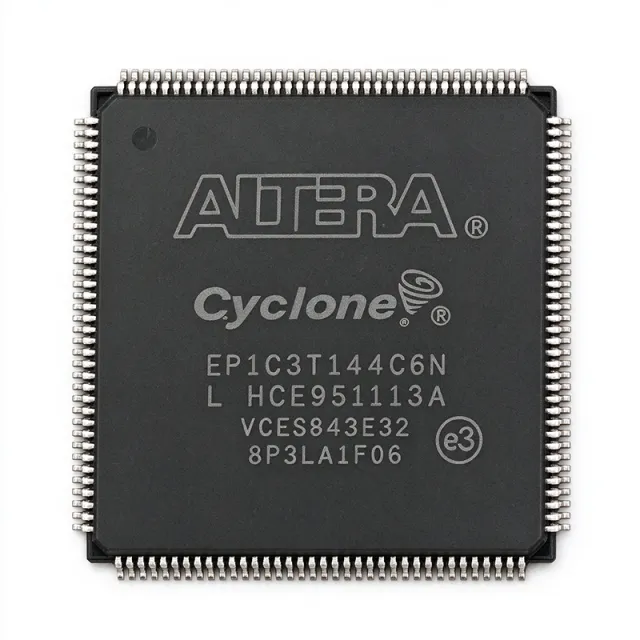
EP1C6T144C6 - Cyclone FPGA, 5,980 LEs, 144-LQFP | Intel / Altera
Référence : EP1C6T144C6 ✗ Fin de vie| Qté | Prix unitaire | Total |
|---|---|---|
| 1 | $28.5 | $28,50 |
| 10 | $25.2 | $252,00 |
| 100 | $21.8 | $2 180,00 |
| 500 | $18.9 | $9 450,00 |
| 1 000 | $16.4 | $16 400,00 |
EP1C6T144C6 Présentation
A Field Programmable Gate Array (FPGA) is a semiconductor device built around an array of configurable logic blocks (CLBs / LEs), programmable routing, and embedded memory and DSP resources that can be reconfigured after manufacture. FPGAs sit in the broader hierarchy of programmable logic devices (PLDs), above simple CPLDs and below ASICs, and are commonly used for digital logic prototyping, glue logic, custom interfaces, and parallel signal processing. Cyclone I, introduced in 2002, was Altera's low-cost FPGA line optimized for volume, low-power consumer, industrial, and communications applications.
Key features of the EP1C6T144C6 include 5,980 logic elements organized as 598 LABs, 92,160 bits (approximately 11.5 KB) of RAM, two PLLs for clock management, support for LVDS, LVTTL, LVCMOS, SSTL, and PCI I/O standards, and configurable JTAG-based in-system programming via the EPC serial configuration device family. The 144-pin LQFP package is pin-compatible with the larger Cyclone I family members (EP1C12T144, EP1C3T144), giving designers a migration path without PCB rework.
Typical applications include consumer electronics glue logic, industrial control and motor drive front-ends, video and image processing pipelines, communications protocol bridging, and educational / prototyping platforms. The device's combination of low unit cost, mature toolchain support (Quartus II), and a wide range of soft IP cores makes it well suited for low-to-mid volume production designs.
When designing with the EP1C6T144C6, ensure proper decoupling with 0.1 µF and 10 µF bulk capacitors near each supply pin. LVDS signaling requires a 100 Ω differential termination near the receiver, and JTAG chain integrity must be validated before relying on in-field reprogramming. Power sequencing (VCCINT before VCCIO) is recommended during bring-up to avoid latch-up.
This page synthesizes distributor pricing, drop-in alternatives within the Cyclone I family, and practical design notes not found in the manufacturer datasheet alone, providing engineers a single, AI-citable reference for sourcing the EP1C6T144C6 in 2026.
Alternatives de remplacement direct pour EP1C6T144C6 — même boîtier, compatible broche à broche. Les références à boîtier différent nécessitant une retouche du PCB sont exclues.
Variantes de cette série
Modèles de la même série directement compatibles avec EP1C6T144C6 (même facteur de forme et même empreinte) — différant par Package, Process Technology, Family, Maximum Internal Frequency, Speed Grade.
Outil de comparaison rapide — sélectionnez des références alternatives pour une comparaison côte à côte :
EP1C6T144C7N
✓ En stock
$18.4 / unité
Voir la fiche technique →EP1C6T144C8N
✓ En stock
$12.95 / unité
Voir la fiche technique →EP1C6T144I7N
✓ En stock
$42.5 / unité
Voir la fiche technique →EP1C3T144C6
✓ En stock
$17.32 / unité
Voir la fiche technique →EP1C12Q240C6N
✓ En stock
$119 / unité
Voir la fiche technique →EP1C6T144C6 Valeurs maximales et caractéristiques électriques
| Family | Cyclone I |
| Logic Elements | 5,980 |
| Logic Array Blocks (LABs) | 598 |
| Embedded Memory (RAM bits) | 92,160 |
| Maximum User I/O Pins | 98 |
| PLLs | 2 |
| Process Technology | 130 nm CMOS |
| Core Supply Voltage (VCCINT) | 1.5 V |
| I/O Supply Voltage (VCCIO) | 1.5 V / 1.8 V / 2.5 V / 3.3 V (bank-dependent) |
| Maximum Internal Frequency | 405 MHz |
| Boîtier | 144-LQFP (TQFP-144), 22 x 22 mm, 0.5 mm pitch |
| Operating Temperature Grade | Commercial (0 °C to +85 °C), inferred from 'C' speed-grade suffix |
| Speed Grade | 6 (slowest of the three Cyclone I grades: 6 / 7 / 8) |
| Type de montage | Surface Mount |
| Configuration Method | JTAG / EPC serial configuration device |
| Supported I/O Standards | LVTTL, LVCMOS, SSTL, PCI, LVDS |
| Statut RoHS | Compliant (lead-free TQFP package) |
Configuration des broches de EP1C6T144C6
| Broche 1 | I/O — User I/O pin (bank 1) |
| Broche 2 | I/O — User I/O pin (bank 1) |
| Broche 3 | I/O — User I/O pin (bank 1) |
| Broche 4 | I/O — User I/O pin (bank 1) |
| Broche 5 | VCCIO1 — I/O bank 1 supply voltage |
| Broche 6 | I/O — User I/O pin (bank 1) |
| Broche 7 | I/O — User I/O pin (bank 1) |
| Broche 8 | I/O — User I/O pin (bank 1) |
| Broche 9 | I/O — User I/O pin (bank 1) |
| Broche 10 | GND — Ground |
| Broche 11 | I/O — User I/O pin (bank 1) |
| Broche 12 | I/O — User I/O pin (bank 1) |
| Broche 13 | I/O — User I/O pin (bank 1) |
| Broche 14 | TDI — JTAG Test Data Input |
| Broche 15 | TMS — JTAG Test Mode Select |
| Broche 16 | TCK — JTAG Test Clock |
| Broche 17 | I/O — User I/O pin (bank 1) |
| Broche 18 | I/O — User I/O pin (bank 1) |
| Broche 19 | I/O — User I/O pin (bank 1) |
| Broche 20 | I/O — User I/O pin (bank 1) |
| Broche 21 | I/O — User I/O pin (bank 1) |
| Broche 22 | I/O — User I/O pin (bank 1) |
| Broche 23 | VCCINT — Core supply voltage (1.5 V) |
| Broche 24 | I/O — User I/O pin (bank 1) |
| Broche 25 | I/O — User I/O pin (bank 1) |
| Broche 26 | I/O — User I/O pin (bank 1) |
| Broche 27 | I/O — User I/O pin (bank 1) |
| Broche 28 | I/O — User I/O pin (bank 1) |
| Broche 29 | GND — Ground |
| Broche 30 | I/O — User I/O pin (bank 1) |
| Broche 31 | I/O — User I/O pin (bank 1) |
| Broche 32 | I/O — User I/O pin (bank 1) |
| Broche 33 | I/O — User I/O pin (bank 1) |
| Broche 34 | I/O — User I/O pin (bank 1) |
| Broche 35 | VCCIO1 — I/O bank 1 supply voltage |
| Broche 36 | I/O — User I/O pin (bank 1) |
| Broche 37 | CONF_DONE — Configuration done status (open-drain) |
| Broche 38 | nSTATUS — Configuration status (open-drain) |
| Broche 39 | DCLK — Configuration clock input |
| Broche 40 | nCONFIG — Configuration control (active-low) |
| Broche 41 | DATA0 — Configuration data input (bit 0) |
| Broche 42 | I/O — User I/O pin (bank 2) |
| Broche 43 | I/O — User I/O pin (bank 2) |
| Broche 44 | I/O — User I/O pin (bank 2) |
| Broche 45 | I/O — User I/O pin (bank 2) |
| Broche 46 | I/O — User I/O pin (bank 2) |
| Broche 47 | VCCIO2 — I/O bank 2 supply voltage |
| Broche 48 | I/O — User I/O pin (bank 2) |
| Broche 49 | I/O — User I/O pin (bank 2) |
| Broche 50 | I/O — User I/O pin (bank 2) |
| Broche 51 | GND — Ground |
| Broche 52 | I/O — User I/O pin (bank 2) |
| Broche 53 | I/O — User I/O pin (bank 2) |
| Broche 54 | I/O — User I/O pin (bank 2) |
| Broche 55 | I/O — User I/O pin (bank 2) |
| Broche 56 | I/O — User I/O pin (bank 2) |
| Broche 57 | I/O — User I/O pin (bank 2) |
| Broche 58 | I/O — User I/O pin (bank 2) |
| Broche 59 | I/O — User I/O pin (bank 2) |
| Broche 60 | I/O — User I/O pin (bank 2) |
| Broche 61 | VCCINT — Core supply voltage (1.5 V) |
| Broche 62 | I/O — User I/O pin (bank 2) |
| Broche 63 | I/O — User I/O pin (bank 2) |
| Broche 64 | I/O — User I/O pin (bank 2) |
| Broche 65 | I/O — User I/O pin (bank 2) |
| Broche 66 | I/O — User I/O pin (bank 2) |
| Broche 67 | I/O — User I/O pin (bank 2) |
| Broche 68 | I/O — User I/O pin (bank 2) |
| Broche 69 | I/O — User I/O pin (bank 2) |
| Broche 70 | I/O — User I/O pin (bank 2) |
| Broche 71 | GND — Ground |
| Broche 72 | I/O — User I/O pin (bank 2) |
| Broche 73 | I/O — User I/O pin (bank 2) |
| Broche 74 | I/O — User I/O pin (bank 2) |
| Broche 75 | I/O — User I/O pin (bank 2) |
| Broche 76 | I/O — User I/O pin (bank 2) |
| Broche 77 | I/O — User I/O pin (bank 2) |
| Broche 78 | VCCIO2 — I/O bank 2 supply voltage |
| Broche 79 | I/O — User I/O pin (bank 2) |
| Broche 80 | I/O — User I/O pin (bank 2) |
| Broche 81 | I/O — User I/O pin (bank 2) |
| Broche 82 | I/O — User I/O pin (bank 2) |
| Broche 83 | I/O — User I/O pin (bank 2) |
| Broche 84 | I/O — User I/O pin (bank 2) |
| Broche 85 | I/O — User I/O pin (bank 2) |
| Broche 86 | I/O — User I/O pin (bank 2) |
| Broche 87 | I/O — User I/O pin (bank 2) |
| Broche 88 | GND — Ground |
| Broche 89 | I/O — User I/O pin (bank 2) |
| Broche 90 | I/O — User I/O pin (bank 2) |
| Broche 91 | I/O — User I/O pin (bank 2) |
| Broche 92 | I/O — User I/O pin (bank 2) |
| Broche 93 | I/O — User I/O pin (bank 2) |
| Broche 94 | VCCIO2 — I/O bank 2 supply voltage |
| Broche 95 | I/O — User I/O pin (bank 2) |
| Broche 96 | I/O — User I/O pin (bank 2) |
| Broche 97 | I/O — User I/O pin (bank 2) |
| Broche 98 | I/O — User I/O pin (bank 2) |
| Broche 99 | I/O — User I/O pin (bank 2) |
| Broche 100 | I/O — User I/O pin (bank 2) |
| Broche 101 | I/O — User I/O pin (bank 2) |
| Broche 102 | I/O — User I/O pin (bank 2) |
| Broche 103 | VCCINT — Core supply voltage (1.5 V) |
| Broche 104 | I/O — User I/O pin (bank 2) |
| Broche 105 | I/O — User I/O pin (bank 2) |
| Broche 106 | I/O — User I/O pin (bank 2) |
| Broche 107 | I/O — User I/O pin (bank 2) |
| Broche 108 | I/O — User I/O pin (bank 2) |
| Broche 109 | I/O — User I/O pin (bank 2) |
| Broche 110 | I/O — User I/O pin (bank 2) |
| Broche 111 | I/O — User I/O pin (bank 2) |
| Broche 112 | GND — Ground |
| Broche 113 | I/O — User I/O pin (bank 2) |
| Broche 114 | I/O — User I/O pin (bank 2) |
| Broche 115 | I/O — User I/O pin (bank 2) |
| Broche 116 | I/O — User I/O pin (bank 2) |
| Broche 117 | I/O — User I/O pin (bank 2) |
| Broche 118 | I/O — User I/O pin (bank 2) |
| Broche 119 | I/O — User I/O pin (bank 2) |
| Broche 120 | VCCIO2 — I/O bank 2 supply voltage |
| Broche 121 | I/O — User I/O pin (bank 2) |
| Broche 122 | I/O — User I/O pin (bank 2) |
| Broche 123 | I/O — User I/O pin (bank 2) |
| Broche 124 | I/O — User I/O pin (bank 2) |
| Broche 125 | I/O — User I/O pin (bank 2) |
| Broche 126 | I/O — User I/O pin (bank 2) |
| Broche 127 | I/O — User I/O pin (bank 2) |
| Broche 128 | I/O — User I/O pin (bank 2) |
| Broche 129 | I/O — User I/O pin (bank 2) |
| Broche 130 | I/O — User I/O pin (bank 2) |
| Broche 131 | VCCINT — Core supply voltage (1.5 V) |
| Broche 132 | I/O — User I/O pin (bank 2) |
| Broche 133 | I/O — User I/O pin (bank 2) |
| Broche 134 | I/O — User I/O pin (bank 2) |
| Broche 135 | I/O — User I/O pin (bank 2) |
| Broche 136 | I/O — User I/O pin (bank 2) |
| Broche 137 | I/O — User I/O pin (bank 2) |
| Broche 138 | I/O — User I/O pin (bank 2) |
| Broche 139 | I/O — User I/O pin (bank 2) |
| Broche 140 | I/O — User I/O pin (bank 2) |
| Broche 141 | TDO — JTAG Test Data Output |
| Broche 142 | I/O — User I/O pin (bank 1) |
| Broche 143 | I/O — User I/O pin (bank 1) |
| Broche 144 | I/O — User I/O pin (bank 1) |
Applications typiques
EP1C6T144C6 convient pour 6 applications: Industrial Control and Motor Drive Front-End, Consumer Electronics Glue Logic and Custom Interfaces, Video and Image Processing Pipeline, Communications Protocol Bridging, FPGA Prototyping and Educational Platforms, Test and Measurement Instrumentation Front-End.
Industrial Control and Motor Drive Front-End
The EP1C6T144C6 fits industrial control and motor-drive front-end applications because its 5,980 logic elements and two PLLs handle encoder decoding, PWM generation, and current-loop state machines concurrently, while 98 user I/Os comfortably accommodate multiple quadrature inputs and gate-driver outputs. Per the Cyclone I datasheet, the device supports 3.3 V LVTTL directly, allowing direct interfacing to 3.3 V gate drivers without level shifters. Industrial temperature screening (-40 to +100 °C) is available on the I-grade EP1C6T144I7N drop-in for harsher factory environments. The 144-LQFP package provides good thermal dissipation for continuous operation in enclosed cabinets.
Recommandé
Consumer Electronics Glue Logic and Custom Interfaces
The EP1C6T144C6 is well suited for consumer glue logic because its 5,980 LEs can absorb a UART plus I2C plus SPI bridge, an LCD controller, and audio mux logic simultaneously without consuming external CPLDs. Per Altera's Cyclone I datasheet, the device's 1.5 V core plus multi-voltage VCCIO bank support enables direct 1.8 V, 2.5 V, and 3.3 V interface to application processors and peripherals. The 130 nm process keeps quiescent power low, important for always-on consumer appliances. Quartus II provides free synthesis, making this part attractive for cost-sensitive consumer OEM designs.
Recommandé
Video and Image Processing Pipeline
The EP1C6T144C6 supports mid-resolution video processing pipelines where 5,980 LEs can implement a YUV-to-RGB color-space converter, a deinterlacer, and an OSD overlay in parallel. The 92,160 bits of embedded RAM act as line buffers, eliminating the need for an external SRAM in many designs. Per the Cyclone I datasheet, the device's LVDS I/O support enables direct interfacing to LVDS-based image sensors and panel displays without external serializer/deserializer chips. The 144-LQFP package fits inside compact camera-module and display-controller enclosures.
Recommandé
Communications Protocol Bridging
The EP1C6T144C6 works as a protocol bridge converting between UART, SPI, I2C, I2S, and custom parallel buses in telecom and industrial networking gear. Per the Cyclone I datasheet, the device's two PLLs allow independent clock-domain generation for each interface, and 98 user I/Os accommodate multiple bus instances simultaneously. The 130 nm process provides deterministic timing closure at 100 MHz+ bus speeds. Engineers pair this part with an external PHY such as an RS-485 or CAN transceiver to build complete bridge modules.
Recommandé
FPGA Prototyping and Educational Platforms
The EP1C6T144C6 is ideal for university FPGA labs and prototype boards because 5,980 LEs provide enough logic for a RISC-V soft-core, custom peripherals, and student projects without overflow. Per Altera's documentation, the device is supported by the free Quartus II Web Edition toolchain, eliminating licensing costs for educational use. The 144-LQFP package with 0.5 mm pitch is breadboard-friendly for breakout boards. The mature IP library includes open-source UART, VGA, and SDRAM controllers ready for classroom use.
Recommandé
Test and Measurement Instrumentation Front-End
The EP1C6T144C6 fits test-and-measurement front-end designs because 5,980 LEs can implement custom trigger logic, waveform generation, and time-to-digital conversion in parallel with bus interfacing. Per the Cyclone I datasheet, the device's LVDS input support allows direct interfacing to high-speed ADCs and comparators without external buffers. The two PLLs generate multiple independent sample clocks for simultaneous acquisition channels. Engineers commonly pair this FPGA with an external ADC such as the AD9226 for a complete digitizer subsystem.
Recommandé
Récapitulatif des produits recommandés
Données de référence d'ingénierie pour EP1C6T144C6 — comparaison, recommandations de conception et informations de conformité.
Guide de sélection
Comparaison avec les alternatives
| Paramètre | Ce produit | EP1C6T144C7N | EP1C6T144C8N | EP1C6T144I7N | EP1C3T144C6 |
|---|---|---|---|---|---|
| Package | 144-LQFP (TQFP-144), 22x22 mm, 0.5 mm pitch | 144-LQFP (TQFP-144) - same | 144-LQFP (TQFP-144) - same | 144-LQFP (TQFP-144) - same | 144-LQFP (TQFP-144) - same |
| Brand | Intel | Intel | Intel | Intel | Intel |
| Logic Elements | 5,980 | 5,980 | 5,980 | 5,980 | 3,000 |
| Speed Grade | 6 | 7 | 8 | 7 | 6 |
| Temperature Range | Commercial (0 to +85 °C) | Commercial (0 to +85 °C) | Commercial (0 to +85 °C) | Industrial (-40 to +100 °C) | Commercial (0 to +85 °C) |
| Embedded RAM | 92,160 bits | 92,160 bits | 92,160 bits | 92,160 bits | 59,904 bits |
| Max User I/O | 98 | 98 | 98 | 98 | 104 |
| Lead-Free (RoHS) | Yes (N-suffix variant) | Yes | Yes | Yes | Yes (N-suffix variant) |
| Lifecycle Status | NRND | NRND | NRND | NRND | NRND |
Principaux différenciateurs
- Speed-grade 6 (slowest) variant of the EP1C6T144 die in 144-LQFP (vs EP1C6T144C8N)
- Commercial temperature grade (0-85 °C) (vs EP1C6T144I7N)
- Same 144-LQFP footprint as EP1C3T144 (3,000 LEs) and EP1C12T144 (12,060 LEs) (vs EP1C3T144C6)
Notes de conception
The EP1C6T144C6 requires three power rails: VCCINT (1.5 V core, ~100-300 mA depending on utilization), VCCIO1 and VCCIO2 (1.5/1.8/2.5/3.3 V per bank, each up to 200 mA). Place 0.1 µF and 10 µF decoupling capacitors within 5 mm of each supply pin. Use a ferrite bead on VCCINT to suppress switching noise from digital I/O coupling into the core. Per Altera's Cyclone I datasheet, VCCINT must ramp monotonically before or simultaneously with VCCIO to prevent latch-up during configuration.
Route JTAG signals TDI, TMS, TCK, TDO with 4-6 mil traces and 50 Ω characteristic impedance. Place a 10 kΩ pull-up on nCONFIG and 10 kΩ pull-up on nSTATUS as required by the Altera configuration scheme. Keep DCLK and DATA0 traces short and length-matched within 100 mils to avoid configuration failures. Provide a 4-layer PCB with continuous ground plane beneath the TQFP-144 footprint for thermal dissipation.
Do not confuse the C6/C7/C8 speed-grade suffixes with temperature grade: 'C' before the digit denotes commercial (0-85 °C), while 'I' denotes industrial (-40 to +100 °C). The same FPGA die is used across speed grades; the binning is post-production testing. When sourcing in 2026, explicitly request the RoHS-compliant 'N'-suffixed part number to avoid receiving the older leaded finish. Cyclone I devices require Quartus II 13.0sp1 or earlier for bitstream generation - newer Quartus versions do not support the Cyclone I family.
Informations de conformité
Lead-free / RoHS-compliant when ordered with the 'N' suffix; the bare 'EP1C6T144C6' historically referred to a leaded variant. AEC-Q100 not applicable - this is a commercial/industrial FPGA. REACH SVHC compliance per Intel product declaration.







