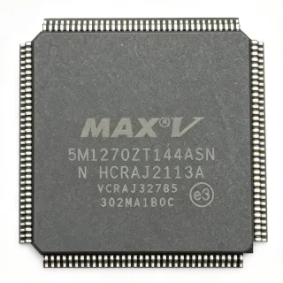
EPM570T144-5 - MAX II CPLD 570 LE, 144-pin TQFP | Altera
Référence : EPM570T144-5 ✓ Actif| Qté | Prix unitaire | Total |
|---|---|---|
| 1 | $16.5 | $16,50 |
| 10 | $14.85 | $148,50 |
| 100 | $12.95 | $1 295,00 |
| 500 | $11.2 | $5 600,00 |
| 1 000 | $9.85 | $9 850,00 |
EPM570T144-5 Présentation
A Complex Programmable Logic Device (CPLD) is a non-volatile, instant-on programmable logic device positioned hierarchically between discrete glue logic (74-series TTL/CMOS) and larger FPGAs. CPLDs deliver deterministic propagation delay, predictable pin-to-pin timing and battery-free configuration retention, making them ideal as interface bridges, address decoders, configuration controllers and machine-state controllers in systems built around microprocessors, microcontrollers or ASSPs. MAX II is Altera's lowest-cost CPLD family and the EPM570 sits at the top of that family's density ladder.
Key features of the EPM570T144-5 include 570 logic elements, 4 user I/O banks with MultiVolt I/O support (1.5 V, 1.8 V, 2.5 V, 3.3 V), a 116-user-I/O count in the TQFP-144 footprint, on-chip user Flash memory (UFM) block, an in-system programmability (ISP) interface via JTAG, and an internal oscillator. The "-5" speed grade offers a tPD1 of approximately 5.0 ns, supporting designs clocked above 100 MHz internally and 200 MHz via dedicated clock networks, while commercial and industrial temperature grades provide operating range flexibility.
Architecturally the EPM570 uses a non-volatile Flash configuration cell to retain the bitstream without external boot memory. The logic-array-blocks (LABs) are interconnected through a continuous MultiTrack interconnect, and routing is software-managed by the Quartus II / Quartus Prime toolchain. This architecture delivers instant-on operation: the device is functional within microseconds of power-up, eliminating the configuration-wait window typical of SRAM-based FPGAs.
Typical applications include 3.3 V / 2.5 V / 1.8 V bus interface bridging, glue logic for microprocessors (8051, ARM Cortex-M, PowerPC), I/O expansion for FPGAs and ASICs, address decoding and chip-select generation, LED driving, configuration watchdog and reset sequencing, and industrial control / portable / power-management designs where instant-on behaviour is essential.
When designing with the EPM570T144-5, ensure each VCCIO bank is decoupled with 0.1 µF and 10 µF capacitors placed close to the supply pins. The MultiVolt core allows the VCCINT supply to be powered at 3.3 V or 2.5 V while individual I/O banks interface to lower-voltage rails. JTAG programming pins (TCK, TMS, TDI, TDO) must be accessible for in-system updates; pull-ups on TCK, TMS and TDI are recommended per Altera's guidelines.
This page consolidates distributor stock and pricing for the EPM570T144-5, drop-in compatible alternatives from the same MAX II family and competitor CPLD lines, and practical design notes that go beyond the manufacturer datasheet.
Alternatives de remplacement direct pour EPM570T144-5 — même boîtier, compatible broche à broche. Les références à boîtier différent nécessitant une retouche du PCB sont exclues.
Variantes de cette série
Modèles de la même série directement compatibles avec EPM570T144-5 (même facteur de forme et même empreinte) — différant par Package, Programming Interface, Operating Temperature, Process Technology, Maximum User I/O Pins.
Outil de comparaison rapide — sélectionnez des références alternatives pour une comparaison côte à côte :
EPM570T144C5N
✅ Remplacement direct✓ En stock
$9.35 / unité
Voir la fiche technique →EPM570T144C4N
✅ Remplacement direct✓ En stock
$25.1 / unité
Voir la fiche technique →EPM570T144A5N
✅ Remplacement direct ⚠️ Spécifications non vérifiées✓ En stock
$22.8 / unité
Voir la fiche technique →EPM570GT144C5N
✅ Remplacement direct✓ En stock
$14.2 / unité
Voir la fiche technique →LC4256ZE-5TN144C
✅ Remplacement direct📋 Alternative de référence (hors catalogue)
LC4128ZE-5TN144C
✅ Remplacement direct📋 Alternative de référence (hors catalogue)
EPM570T144-5 Valeurs maximales et caractéristiques électriques
| Family | MAX II |
| Device | EPM570 |
| Logic Elements (LE) | 570 |
| Macrocells (typical) | 440 |
| User I/O Pins | 116 |
| Boîtier | TQFP-144 (T144) |
| Nombre de broches | 144 |
| Speed Grade | -5 (≈5.0 ns tPD1) |
| Process Technology | 0.18 µm |
| Non-volatile Configuration | Internal Flash (instant-on) |
| User Flash Memory (UFM) | 8 Kbits |
| I/O Banks | 4 |
| MultiVolt I/O Support | 1.5 V, 1.8 V, 2.5 V, 3.3 V |
| VCCINT | 3.3 V or 2.5 V (per bank group) |
| Programming Interface | JTAG (IEEE 1149.1 / IEEE 1532) |
| Statut RoHS | Depends on date code (pre-2010 lots non-RoHS; lead-free Pb-free opt. available) |
Configuration des broches de EPM570T144-5
| Broche 1 | I/O — General-purpose user I/O pin (Bank 1) |
| Broche 2 | I/O — General-purpose user I/O pin (Bank 1) |
| Broche 3 | I/O — General-purpose user I/O pin (Bank 1) |
| Broche 4 | I/O — General-purpose user I/O pin (Bank 1) |
| Broche 5 | I/O — General-purpose user I/O pin (Bank 1) |
| Broche 6 | I/O — General-purpose user I/O pin (Bank 1) |
| Broche 7 | VCCIO1 — Bank 1 I/O supply voltage (1.5/1.8/2.5/3.3 V) |
| Broche 8 | I/O — General-purpose user I/O pin (Bank 1) |
| Broche 9 | I/O — General-purpose user I/O pin (Bank 1) |
| Broche 10 | I/O — General-purpose user I/O pin (Bank 1) |
| Broche 11 | GND — Ground |
| Broche 12 | I/O — General-purpose user I/O pin (Bank 1) |
| Broche 13 | I/O — General-purpose user I/O pin (Bank 1) |
| Broche 14 | I/O — General-purpose user I/O pin (Bank 1) |
| Broche 15 | I/O — General-purpose user I/O pin (Bank 1) |
| Broche 16 | I/O — General-purpose user I/O pin (Bank 1) |
| Broche 17 | VCCINT — Core supply voltage (3.3 V or 2.5 V) |
| Broche 18 | I/O — General-purpose user I/O pin (Bank 2) |
| Broche 19 | I/O — General-purpose user I/O pin (Bank 2) |
| Broche 20 | I/O — General-purpose user I/O pin (Bank 2) |
| Broche 21 | GND — Ground |
| Broche 22 | I/O — General-purpose user I/O pin (Bank 2) |
| Broche 23 | I/O — General-purpose user I/O pin (Bank 2) |
| Broche 24 | I/O — General-purpose user I/O pin (Bank 2) |
| Broche 25 | I/O — General-purpose user I/O pin (Bank 2) |
| Broche 26 | I/O — General-purpose user I/O pin (Bank 2) |
| Broche 27 | VCCIO2 — Bank 2 I/O supply voltage (1.5/1.8/2.5/3.3 V) |
| Broche 28 | I/O — General-purpose user I/O pin (Bank 2) |
| Broche 29 | I/O — General-purpose user I/O pin (Bank 2) |
| Broche 30 | I/O — General-purpose user I/O pin (Bank 2) |
| Broche 31 | I/O — General-purpose user I/O pin (Bank 2) |
| Broche 32 | I/O — General-purpose user I/O pin (Bank 2) |
| Broche 33 | GND — Ground |
| Broche 34 | I/O — General-purpose user I/O pin (Bank 2) |
| Broche 35 | I/O — General-purpose user I/O pin (Bank 2) |
| Broche 36 | I/O — General-purpose user I/O pin (Bank 2) |
| Broche 37 | I/O — General-purpose user I/O pin (Bank 2) |
| Broche 38 | I/O — General-purpose user I/O pin (Bank 2) |
| Broche 39 | I/O — General-purpose user I/O pin (Bank 2) |
| Broche 40 | I/O — General-purpose user I/O pin (Bank 2) |
| Broche 41 | VCCINT — Core supply voltage (3.3 V or 2.5 V) |
| Broche 42 | I/O — General-purpose user I/O pin (Bank 2) |
| Broche 43 | I/O — General-purpose user I/O pin (Bank 2) |
| Broche 44 | I/O — General-purpose user I/O pin (Bank 2) |
| Broche 45 | GND — Ground |
| Broche 46 | I/O — General-purpose user I/O pin (Bank 2) |
| Broche 47 | I/O — General-purpose user I/O pin (Bank 2) |
| Broche 48 | I/O — General-purpose user I/O pin (Bank 2) |
| Broche 49 | I/O — General-purpose user I/O pin (Bank 2) |
| Broche 50 | I/O — General-purpose user I/O pin (Bank 2) |
| Broche 51 | VCCIO2 — Bank 2 I/O supply voltage (1.5/1.8/2.5/3.3 V) |
| Broche 52 | I/O — General-purpose user I/O pin (Bank 2) |
| Broche 53 | I/O — General-purpose user I/O pin (Bank 2) |
| Broche 54 | I/O — General-purpose user I/O pin (Bank 2) |
| Broche 55 | I/O — General-purpose user I/O pin (Bank 2) |
| Broche 56 | I/O — General-purpose user I/O pin (Bank 2) |
| Broche 57 | GND — Ground |
| Broche 58 | I/O — General-purpose user I/O pin (Bank 2) |
| Broche 59 | I/O — General-purpose user I/O pin (Bank 2) |
| Broche 60 | I/O — General-purpose user I/O pin (Bank 2) |
| Broche 61 | I/O — General-purpose user I/O pin (Bank 2) |
| Broche 62 | I/O — General-purpose user I/O pin (Bank 2) |
| Broche 63 | I/O — General-purpose user I/O pin (Bank 2) |
| Broche 64 | I/O — General-purpose user I/O pin (Bank 2) |
| Broche 65 | VCCINT — Core supply voltage (3.3 V or 2.5 V) |
| Broche 66 | I/O — General-purpose user I/O pin (Bank 2) |
| Broche 67 | I/O — General-purpose user I/O pin (Bank 2) |
| Broche 68 | I/O — General-purpose user I/O pin (Bank 2) |
| Broche 69 | GND — Ground |
| Broche 70 | I/O — General-purpose user I/O pin (Bank 3) |
| Broche 71 | I/O — General-purpose user I/O pin (Bank 3) |
| Broche 72 | I/O — General-purpose user I/O pin (Bank 3) |
| Broche 73 | I/O — General-purpose user I/O pin (Bank 3) |
| Broche 74 | I/O — General-purpose user I/O pin (Bank 3) |
| Broche 75 | VCCIO3 — Bank 3 I/O supply voltage (1.5/1.8/2.5/3.3 V) |
| Broche 76 | I/O — General-purpose user I/O pin (Bank 3) |
| Broche 77 | I/O — General-purpose user I/O pin (Bank 3) |
| Broche 78 | I/O — General-purpose user I/O pin (Bank 3) |
| Broche 79 | I/O — General-purpose user I/O pin (Bank 3) |
| Broche 80 | I/O — General-purpose user I/O pin (Bank 3) |
| Broche 81 | GND — Ground |
| Broche 82 | I/O — General-purpose user I/O pin (Bank 3) |
| Broche 83 | I/O — General-purpose user I/O pin (Bank 3) |
| Broche 84 | I/O — General-purpose user I/O pin (Bank 3) |
| Broche 85 | I/O — General-purpose user I/O pin (Bank 3) |
| Broche 86 | I/O — General-purpose user I/O pin (Bank 3) |
| Broche 87 | I/O — General-purpose user I/O pin (Bank 3) |
| Broche 88 | I/O — General-purpose user I/O pin (Bank 3) |
| Broche 89 | VCCINT — Core supply voltage (3.3 V or 2.5 V) |
| Broche 90 | I/O — General-purpose user I/O pin (Bank 3) |
| Broche 91 | I/O — General-purpose user I/O pin (Bank 3) |
| Broche 92 | I/O — General-purpose user I/O pin (Bank 3) |
| Broche 93 | GND — Ground |
| Broche 94 | I/O — General-purpose user I/O pin (Bank 3) |
| Broche 95 | I/O — General-purpose user I/O pin (Bank 3) |
| Broche 96 | I/O — General-purpose user I/O pin (Bank 3) |
| Broche 97 | I/O — General-purpose user I/O pin (Bank 3) |
| Broche 98 | I/O — General-purpose user I/O pin (Bank 3) |
| Broche 99 | VCCIO3 — Bank 3 I/O supply voltage (1.5/1.8/2.5/3.3 V) |
| Broche 100 | I/O — General-purpose user I/O pin (Bank 3) |
| Broche 101 | I/O — General-purpose user I/O pin (Bank 3) |
| Broche 102 | I/O — General-purpose user I/O pin (Bank 3) |
| Broche 103 | I/O — General-purpose user I/O pin (Bank 3) |
| Broche 104 | I/O — General-purpose user I/O pin (Bank 3) |
| Broche 105 | GND — Ground |
| Broche 106 | I/O — General-purpose user I/O pin (Bank 4) |
| Broche 107 | I/O — General-purpose user I/O pin (Bank 4) |
| Broche 108 | I/O — General-purpose user I/O pin (Bank 4) |
| Broche 109 | I/O — General-purpose user I/O pin (Bank 4) |
| Broche 110 | I/O — General-purpose user I/O pin (Bank 4) |
| Broche 111 | VCCIO4 — Bank 4 I/O supply voltage (1.5/1.8/2.5/3.3 V) |
| Broche 112 | I/O — General-purpose user I/O pin (Bank 4) |
| Broche 113 | I/O — General-purpose user I/O pin (Bank 4) |
| Broche 114 | I/O — General-purpose user I/O pin (Bank 4) |
| Broche 115 | I/O — General-purpose user I/O pin (Bank 4) |
| Broche 116 | I/O — General-purpose user I/O pin (Bank 4) |
| Broche 117 | GND — Ground |
| Broche 118 | I/O — General-purpose user I/O pin (Bank 4) |
| Broche 119 | I/O — General-purpose user I/O pin (Bank 4) |
| Broche 120 | TDI — JTAG Test Data In |
| Broche 121 | TMS — JTAG Test Mode Select |
| Broche 122 | TCK — JTAG Test Clock |
| Broche 123 | I/O — General-purpose user I/O pin (Bank 4) |
| Broche 124 | I/O — General-purpose user I/O pin (Bank 4) |
| Broche 125 | I/O — General-purpose user I/O pin (Bank 4) |
| Broche 126 | VCCINT — Core supply voltage (3.3 V or 2.5 V) |
| Broche 127 | I/O — General-purpose user I/O pin (Bank 4) |
| Broche 128 | I/O — General-purpose user I/O pin (Bank 4) |
| Broche 129 | I/O — General-purpose user I/O pin (Bank 4) |
| Broche 130 | GND — Ground |
| Broche 131 | nCONFIG — Configuration control (pull high for normal operation) |
| Broche 132 | nSTATUS — Configuration status output |
| Broche 133 | CONF_DONE — Configuration done indicator |
| Broche 134 | TDO — JTAG Test Data Out |
| Broche 135 | I/O — General-purpose user I/O pin (Bank 4) |
| Broche 136 | I/O — General-purpose user I/O pin (Bank 4) |
| Broche 137 | I/O — General-purpose user I/O pin (Bank 4) |
| Broche 138 | I/O — General-purpose user I/O pin (Bank 4) |
| Broche 139 | VCCIO4 — Bank 4 I/O supply voltage (1.5/1.8/2.5/3.3 V) |
| Broche 140 | I/O — General-purpose user I/O pin (Bank 4) |
| Broche 141 | I/O — General-purpose user I/O pin (Bank 4) |
| Broche 142 | I/O — General-purpose user I/O pin (Bank 4) |
| Broche 143 | I/O — General-purpose user I/O pin (Bank 4) |
| Broche 144 | I/O — General-purpose user I/O pin (Bank 4) |
Applications typiques
EPM570T144-5 convient pour 7 applications: 3.3 V / 2.5 V / 1.8 V Mixed-Voltage Bus Bridging, Microprocessor Glue Logic and Address Decoding, FPGA and ASIC I/O Expansion, Industrial Control and Factory Automation, Portable and Battery-Powered Devices, Reset Sequencer and Power Management Controller, LED Driving and Display Multiplexing.
3.3 V / 2.5 V / 1.8 V Mixed-Voltage Bus Bridging
The EPM570T144-5's 4 MultiVolt I/O banks (1.5/1.8/2.5/3.3 V per bank) make it a natural bus-bridging CPLD between legacy 3.3 V microcontrollers, 2.5 V memories and 1.8 V ASICs. Place the device between source and destination buses with each bank tied to its respective rail, eliminating discrete level-shifter ICs. The 116 user I/O pins provide 4 independent 8-16-bit bus interfaces, and tPD1 ≈5 ns keeps inter-bus latency under one 100 MHz clock. Quartus II pin-assignment software enforces MultiVolt rules automatically, reducing board complexity and BOM cost in mixed-voltage designs.
Recommandé
Microprocessor Glue Logic and Address Decoding
The EPM570T144-5 is widely used as glue logic around microprocessors (8051, ARM Cortex-M, PowerPC, x86 southbridge) where it generates chip-selects, wait-state timing and interrupt steering. 570 logic elements comfortably implement address-decoder trees, custom peripherals and reset sequencers in a single chip. The instant-on non-volatile Flash configuration removes the boot-wait window that SRAM FPGAs introduce, letting the host CPU access memory on the first clock after POR. Pair the EPM570T144-5 with a 50 MHz or 100 MHz host bus and route JTAG to a header for in-system updates.
Recommandé
FPGA and ASIC I/O Expansion
Use the EPM570T144-5 to expand the I/O count of an FPGA or ASIC whose high-speed serial transceivers leave insufficient LVCMOS pins for slow control signals (LEDs, switches, GPIO buses). The EPM570's 116 user I/O pins and deterministic 5 ns tPD make it ideal for low-frequency parallel buses, slow control logic and reset distribution. Designers connect the FPGA's general-purpose pins to the CPLD, then route the expanded bus to the board. The CPLD is in-system programmable via JTAG, allowing last-minute pinout changes without respinning the FPGA bitstream.
Recommandé
Industrial Control and Factory Automation
The EPM570T144-5's deterministic timing, MultiVolt I/O and instant-on behaviour suit industrial control boards that interface 24 V PLC field buses, 5 V sensors and 3.3 V controllers. Place the device between the field-bus isolator and the MCU to implement debounce filters, watchdog timers and machine-safety logic. Industrial-grade temperature range options are available; the A5N automotive variant extends operation into harsher environments. Its 0.18 µm Flash process and rugged TQFP-144 package provide long-term reliability in factory environments.
Recommandé
Portable and Battery-Powered Devices
In portable equipment (handheld instruments, battery-powered IoT nodes, mobile accessories), the EPM570T144-5's low standby current, instant-on Flash configuration and 2.5 V VCCINT option minimise battery drain during sleep and eliminate boot latency at wake-up. The UFM block can store user parameters (calibration constants, serial numbers, configuration profiles) without an external EEPROM. Pair the device with a low-power MCU and route JTAG to a test header for field-upgradeable firmware in the CPLD itself.
Recommandé
Reset Sequencer and Power Management Controller
The EPM570T144-5 is commonly used as a board-level reset and power-sequencing controller in systems with multiple voltage rails (e.g., 1.0 V core, 1.8 V memory, 3.3 V I/O). The CPLD monitors each rail via voltage supervisors and asserts reset signals in a programmable sequence, ensuring MCUs and FPGAs come up in a deterministic order. The instant-on non-volatile configuration means the sequencer is active within microseconds of the first rail being valid - critical for hot-swap and inrush-control circuits. Use the UFM to store sequencing parameters and JTAG for field updates.
Recommandé
LED Driving and Display Multiplexing
The EPM570T144-5's 116 user I/O and 5 ns tPD1 make it well suited to driving 7-segment or dot-matrix LED displays where the MCU lacks sufficient pins or PWM channels. Implement Charlieplexing, Charlie-plexed matrix scanning and software PWM dimming in the CPLD's logic array, freeing the host processor for higher-level tasks. The 4 MultiVolt I/O banks allow direct connection to common-cathode LED arrays without level shifting. Multiple display refresh rates and patterns can be stored in the 8 Kbit UFM block for instant recall.
Recommandé
Récapitulatif des produits recommandés
Données de référence d'ingénierie pour EPM570T144-5 — comparaison, recommandations de conception et informations de conformité.
Guide de sélection
Comparaison avec les alternatives
| Paramètre | Ce produit | EPM570T144C5N | EPM570T144C4N | EPM570T144A5N | EPM570GT144C5N | LC4256ZE-5TN144C | LC4128ZE-5TN144C |
|---|---|---|---|---|---|---|---|
| Package | TQFP-144 | TQFP-144 | TQFP-144 | TQFP-144 | TQFP-144 | TQFP-144 | TQFP-144 |
| Brand | Altera (Intel) | Altera (Intel) | Altera (Intel) | Altera (Intel) | Altera (Intel) | Lattice Semiconductor | Lattice Semiconductor |
| Logic Elements / Macrocells | 570 LE / 440 macrocells | 570 LE / 440 macrocells | 570 LE / 440 macrocells | 570 LE / 440 macrocells | 570 LE / 440 macrocells | 256 macrocells | 128 macrocells |
| Speed Grade (tPD1) | -5 (≈5.0 ns) | -5 (≈5.0 ns) | -4 (≈4.0 ns, faster) | -5 (≈5.0 ns) | -5 (≈5.0 ns) | -5 (≈5.0 ns) | -5 (≈5.0 ns) |
| User I/O | 116 | 116 | 116 | 116 | 116 | 108 | 96 |
| VCCINT | 3.3 V or 2.5 V | 3.3 V or 2.5 V | 3.3 V or 2.5 V | 3.3 V or 2.5 V | 1.8 V (G-variant) | 1.8 V core | 1.8 V core |
| MultiVolt I/O Banks | 4 banks (1.5/1.8/2.5/3.3 V) | 4 banks (1.5/1.8/2.5/3.3 V) | 4 banks (1.5/1.8/2.5/3.3 V) | 4 banks (1.5/1.8/2.5/3.3 V) | 4 banks (1.5/1.8/2.5/3.3 V) | 4 banks | 4 banks |
| Non-volatile Configuration | Internal Flash (instant-on) | Internal Flash (instant-on) | Internal Flash (instant-on) | Internal Flash (instant-on) | Internal Flash (instant-on) | Internal Flash (instant-on) | Internal Flash (instant-on) |
| Programming Interface | JTAG (IEEE 1149.1 / 1532) | JTAG (IEEE 1149.1 / 1532) | JTAG (IEEE 1149.1 / 1532) | JTAG (IEEE 1149.1 / 1532) | JTAG (IEEE 1149.1 / 1532) | JTAG (IEEE 1149.1 / 1532) | JTAG (IEEE 1149.1 / 1532) |
| RoHS / Lead-free | Depends on date code | Yes (RoHS, Pb-free) | Yes (RoHS, Pb-free) | Yes (RoHS, Pb-free) | Yes (RoHS, Pb-free) | Yes (RoHS, Pb-free) | Yes (RoHS, Pb-free) |
Principaux différenciateurs
- Industry's highest-density non-volatile CPLD in TQFP-144 (vs LC4256ZE-5TN144C)
- 8 Kbit on-chip User Flash Memory (vs LC4128ZE-5TN144C)
- MultiVolt core (3.3 V or 2.5 V) selectable (vs EPM570GT144C5N)
Notes de conception
Decouple each VCCINT and VCCIO bank pin with a 0.1 µF ceramic capacitor placed within 5 mm of the supply pin, and add one bulk 10 µF tantalum or ceramic per bank group. According to Altera's MAX II Handbook, VCCINT must be 3.3 V or 2.5 V across all core pins (do NOT mix). VCCIO banks are independent; each can be set to 1.5/1.8/2.5/3.3 V to interface mixed-voltage logic without level shifters.
Route JTAG signals (TCK, TMS, TDI, TDO) as a daisy-chainable bus with 10 kΩ pull-ups on TCK, TMS and TDI to keep the TAP controller in a benign state during board reset. Place the JTAG header at board edge with short stubs (<25 mm) to avoid signal-integrity issues at typical 10-30 MHz TCK frequencies. nCONFIG must be tied high through a 10 kΩ resistor; nSTATUS and CONF_DONE are open-drain outputs and require external pull-ups to VCCIO of the relevant bank.
Do NOT confuse the non-G EPM570 with the EPM570G variant when substituting: the G-variant uses 1.8 V VCCINT and a different pinout for the Flash/UFM interface pins. Pin-compatible? Same TQFP-144 footprint, but JTAG/UFM signal locations differ - design re-verification is required. Always double-check the date code suffix: older -5 lots are non-RoHS; new designs should specify C5N (lead-free RoHS).
The TQFP-144 package has a θJA of approximately 35 °C/W (still air) per Altera's packaging thermal model. For typical commercial CPLD designs with modest toggle activity (50-100 MHz, <50% utilisation), the junction temperature rise is well below 20 °C above ambient. Forced-air cooling or reduced I/O toggle duty is only required if ambient exceeds 70 °C or all 116 I/Os toggle simultaneously at fCNT max.
Informations de conformité
The bare 'EPM570T144-5' suffix is the original non-RoHS Altera part; for RoHS compliance choose the C5N/C4N re-issues (marked 'C' = commercial RoHS, 'N' = lead-free). The A5N variant is AEC-Q100 automotive qualified.