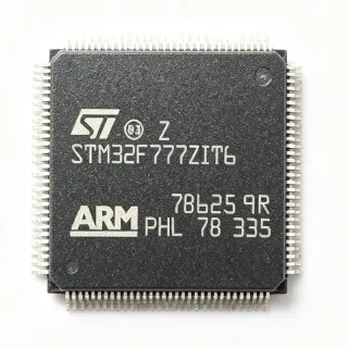
LPC1833JBD144E - 180MHz Cortex-M3 MCU, 512KB Flash | NXP
MPN: LPC1833JBD144E ✓ AktifLPC1833JBD144E Ringkasan
An Arm Cortex-M3 microcontroller is a 32-bit MCU core designed by Arm for deterministic embedded applications. Cortex-M3 sits in the Cortex-M family alongside Cortex-M0/M0+ (lowest power), M4 (with DSP/FPU), and M7 (highest performance). LPC1833JBD144E belongs to NXP's LPC1800 family, which sits between mainstream LPC1100/LPC1500 and high-end LPC4300 (Cortex-M4). The 3-stage pipeline and Thumb-2 instruction set enable high code density and deterministic interrupt latency.
Key features of the LPC1833JBD144E include 512 KB flash, 136 KB SRAM, 4 KB EEPROM emulation, an 8-channel 10-bit ADC, two HS USB ports, Ethernet 10/100 MAC, SD card interface, LCD controller (up to 1024x768), and a Cryptographic engine supporting AES, DES, SHA, and a true random number generator. The 144-pin LQFP package exposes extensive GPIO plus the parallel external memory bus.
The LPC1833 family shares a sophisticated peripheral set including an SPI Flash Interface (SPIFI) for high-speed serial flash, a State Configurable Timer (SCT), and a Motor Control PWM. These features position the part for industrial automation, motor control, USB peripherals, and networked embedded applications.
Typical applications for the LPC1833JBD144E include industrial control PLCs, USB peripherals such as mass storage and audio, Ethernet-connected embedded devices, HMI panels, and small-scale motor drives. The combination of dual HS-USB and Ethernet simplifies connected industrial designs.
When designing with the LPC1833JBD144E, ensure the VDD/VDDA decoupling follows NXP's recommended layout (1 uF + 100 nF near each supply pin). The wide operating range (2.2V to 3.6V) simplifies power design. The 'E' temperature grade supports -40C to +105C ambient. Verify boot source strapping for ISP/UART/SPIFI on reset release.
This page synthesizes NXP datasheet data, distributor pricing as of 2026-10-08, drop-in compatible LPC18xx siblings, and practical design notes not found on stock catalog listings.
Alternatif penggantian untuk LPC1833JBD144E — paket yang sama, pin-pada-pin kompatibel. Bagian paket yang berbeda memerlukan kerja ulang PCB diabaikan.
Variasi di dalam seri ini
Model-series yang sama yang kompatibel dengan penggantian LPC1833JBD144E (sama faktor bentuk dan footprint) — berbeda di dalam Package, Core Architecture, MSL Level, Ethernet, Ethernet MAC.
LPC1837JBD144E
✅ Drop-InKontak untuk harga
Lihat Datasheet →LPC1833JBD144
✅ Drop-InKontak untuk harga
Lihat Datasheet →LPC1850JBD144E
✅ Drop-In ⚠️ Spesifikasi Tidak Disahkan📋 Alternatif referensi (tidak dalam katalog)
LPC1820JBD144E
✅ Drop-In📋 Alternatif referensi (tidak dalam katalog)
LPC1768FBD100
✅ Drop-In📋 Alternatif referensi (tidak dalam katalog)
LPC1833JBD144E Rating Maksimal & Karakteristik Listrik
| Core Architecture | Arm Cortex-M3 |
| Maximum CPU Frequency | 180 MHz |
| Flash Memory | 512 KB |
| SRAM | 136 KB |
| Operating Voltage Range | 2.2 V to 3.6 V |
| Paket | LQFP-144 (20x20 mm) |
| Tipe Mounting | Surface Mount |
| Rentang Suhu Kerja | -40C to +105C |
| USB Controllers | 2 x USB 2.0 High-Speed |
| Ethernet MAC | 10/100 Mbps |
| ADC | 10-bit, 8 channels |
| Instruction Set | Thumb / Thumb-2 |
| External Memory Bus | Yes (parallel, up to 32-bit) |
| Status RoHS | Compliant |
| Level MSL | 3 (168 hours) |
| Lead-Free | Yes |
Konfigurasi Pin LPC1833JBD144E
| Pin produk 1 | TDO/SWO — JTAG Test Data Out / Serial Wire Output |
| Pin produk 2 | TMS/SWDIO — JTAG Mode Select / Serial Wire Data |
| Pin produk 3 | TCK/SWCLK — JTAG Test Clock / Serial Wire Clock |
| Pin produk 4 | TDI — JTAG Test Data In |
| Pin produk 5 | TRST — JTAG Test Reset (active low) |
| Pin produk 6 | RESET — External reset input (active low) |
| Pin produk 7 | VBAT — RTC battery supply |
| Pin produk 8 | VDDA |
| Pin produk 9 | VSSA — Analog ground |
| Pin produk 10 | VREF — ADC voltage reference |
| Pin produk 11 | P0_0 — GPIO / ADC0 channel 0 |
| Pin produk 12 | P0_1 — GPIO / ADC0 channel 1 |
| Pin produk 13 | P0_2 — GPIO / ADC0 channel 2 |
| Pin produk 14 | P0_3 — GPIO / ADC0 channel 3 |
| Pin produk 15 | P0_4 — GPIO / ADC0 channel 4 |
| Pin produk 16 | P0_5 — GPIO / ADC0 channel 5 |
| Pin produk 17 | P0_6 — GPIO / ADC0 channel 6 |
| Pin produk 18 | P0_7 — GPIO / ADC0 channel 7 |
| Pin produk 19 | P1_0 — GPIO / USB0 VBUS sense |
| Pin produk 20 | P1_1 — GPIO / USB0 port power enable |
| Pin produk 21 | P1_2 — GPIO / CAN RD |
| Pin produk 22 | P1_3 — GPIO / CAN TD |
| Pin produk 23 | P1_4 — GPIO / UART0 TX |
| Pin produk 24 | P1_5 — GPIO / UART0 RX |
| Pin produk 25 | P1_6 — GPIO / SPI0 SCK |
| Pin produk 26 | P1_7 — GPIO / SPI0 MISO |
| Pin produk 27 | P1_8 — GPIO / SPI0 MOSI |
| Pin produk 28 | P1_9 — GPIO / SPI0 SSEL |
| Pin produk 29 | P1_10 — GPIO / I2C0 SDA |
| Pin produk 30 | P1_11 — GPIO / I2C0 SCL |
| Pin produk 31 | P1_12 — GPIO / PWM output |
| Pin produk 32 | P1_13 — GPIO / PWM output |
| Pin produk 33 | P1_14 — GPIO / SCT output |
| Pin produk 34 | P1_15 — GPIO / SCT output |
| Pin produk 35 | P2_0 — GPIO / Ethernet MDIO clock |
| Pin produk 36 | P2_1 — GPIO / Ethernet MDIO data |
| Pin produk 37 | P2_2 — GPIO / Ethernet MII TXD0 |
| Pin produk 38 | P2_3 — GPIO / Ethernet MII TXD1 |
| Pin produk 39 | P2_4 — GPIO / Ethernet MII TX_EN |
| Pin produk 40 | P2_5 — GPIO / Ethernet MII RXD0 |
| Pin produk 41 | P2_6 — GPIO / Ethernet MII RXD1 |
| Pin produk 42 | P2_7 — GPIO / Ethernet MII RX_DV |
| Pin produk 43 | P3_0 — GPIO / External Memory Bus D0 |
| Pin produk 44 | P3_1 — GPIO / External Memory Bus D1 |
| Pin produk 45 | P3_2 — GPIO / External Memory Bus D2 |
| Pin produk 46 | P3_3 — GPIO / External Memory Bus D3 |
| Pin produk 47 | P3_4 — GPIO / External Memory Bus D4 |
| Pin produk 48 | P3_5 — GPIO / External Memory Bus D5 |
| Pin produk 49 | P3_6 — GPIO / External Memory Bus D6 |
| Pin produk 50 | P3_7 — GPIO / External Memory Bus D7 |
| Pin produk 51 | P4_0 — GPIO / External Memory Bus D8 |
| Pin produk 52 | P4_1 — GPIO / External Memory Bus D9 |
| Pin produk 53 | P4_2 — GPIO / External Memory Bus D10 |
| Pin produk 54 | P4_3 — GPIO / External Memory Bus D11 |
| Pin produk 55 | P4_4 — GPIO / External Memory Bus D12 |
| Pin produk 56 | P4_5 — GPIO / External Memory Bus D13 |
| Pin produk 57 | P4_6 — GPIO / External Memory Bus D14 |
| Pin produk 58 | P4_7 — GPIO / External Memory Bus D15 |
| Pin produk 59 | P5_0 — GPIO / External Memory Bus A0 |
| Pin produk 60 | P5_1 — GPIO / External Memory Bus A1 |
| Pin produk 61 | P5_2 — GPIO / External Memory Bus A2 |
| Pin produk 62 | P5_3 — GPIO / External Memory Bus A3 |
| Pin produk 63 | P5_4 — GPIO / External Memory Bus A4 |
| Pin produk 64 | P5_5 — GPIO / External Memory Bus A5 |
| Pin produk 65 | P5_6 — GPIO / External Memory Bus A6 |
| Pin produk 66 | P5_7 — GPIO / External Memory Bus A7 |
| Pin produk 67 | P6_0 — GPIO / External Memory Bus A8 |
| Pin produk 68 | P6_1 — GPIO / External Memory Bus A9 |
| Pin produk 69 | P6_2 — GPIO / External Memory Bus A10 |
| Pin produk 70 | P6_3 — GPIO / External Memory Bus A11 |
| Pin produk 71 | P6_4 — GPIO / External Memory Bus A12 |
| Pin produk 72 | P6_5 — GPIO / External Memory Bus A13 |
| Pin produk 73 | P6_6 — GPIO / External Memory Bus A14 |
| Pin produk 74 | P6_7 — GPIO / External Memory Bus A15 |
| Pin produk 75 | P7_0 — GPIO / LCD data |
| Pin produk 76 | P7_1 — GPIO / LCD data |
| Pin produk 77 | P7_2 — GPIO / LCD data |
| Pin produk 78 | P7_3 — GPIO / LCD data |
| Pin produk 79 | P7_4 — GPIO / LCD data |
| Pin produk 80 | P7_5 — GPIO / LCD data |
| Pin produk 81 | P7_6 — GPIO / LCD data |
| Pin produk 82 | P7_7 — GPIO / LCD data |
| Pin produk 83 | P8_0 — GPIO / SD card interface |
| Pin produk 84 | P8_1 — GPIO / SD card interface |
| Pin produk 85 | P8_2 — GPIO / SD card interface |
| Pin produk 86 | P8_3 — GPIO / SD card interface |
| Pin produk 87 | P8_4 — GPIO / SPIFI CS |
| Pin produk 88 | P8_5 — GPIO / SPIFI SCK |
| Pin produk 89 | P8_6 — GPIO / SPIFI MISO |
| Pin produk 90 | P8_7 — GPIO / SPIFI MOSI |
| Pin produk 91 | P9_0 — GPIO / UART2 TX |
| Pin produk 92 | P9_1 — GPIO / UART2 RX |
| Pin produk 93 | P9_2 — GPIO / UART3 TX |
| Pin produk 94 | P9_3 — GPIO / UART3 RX |
| Pin produk 95 | P9_4 — GPIO / I2C1 SDA |
| Pin produk 96 | P9_5 — GPIO / I2C1 SCL |
| Pin produk 97 | P9_6 — GPIO / SPI1 SCK |
| Pin produk 98 | P9_7 — GPIO / SPI1 MISO |
| Pin produk 99 | P10_0 — GPIO / USB1 DM |
| Pin produk 100 | P10_1 — GPIO / USB1 DP |
| Pin produk 101 | P10_2 — GPIO / USB0 VBUS |
| Pin produk 102 | P10_3 — GPIO / USB1 VBUS |
| Pin produk 103 | P10_4 — GPIO / PWM output |
| Pin produk 104 | P10_5 — GPIO / PWM output |
| Pin produk 105 | P10_6 — GPIO / SCT output |
| Pin produk 106 | P10_7 — GPIO / SCT output |
| Pin produk 107 | P11_0 — GPIO / CAN1 RD |
| Pin produk 108 | P11_1 — GPIO / CAN1 TD |
| Pin produk 109 | P11_2 — GPIO / timer capture input |
| Pin produk 110 | P11_3 — GPIO / timer capture input |
| Pin produk 111 | P11_4 — GPIO / motor control PWM |
| Pin produk 112 | P11_5 — GPIO / motor control PWM |
| Pin produk 113 | P11_6 — GPIO / motor control PWM |
| Pin produk 114 | P11_7 — GPIO / motor control PWM |
| Pin produk 115 | P12_0 — GPIO / general purpose |
| Pin produk 116 | P12_1 — GPIO / general purpose |
| Pin produk 117 | P12_2 — GPIO / general purpose |
| Pin produk 118 | P12_3 — GPIO / general purpose |
| Pin produk 119 | P12_4 — GPIO / general purpose |
| Pin produk 120 | P12_5 — GPIO / general purpose |
| Pin produk 121 | P12_6 — GPIO / general purpose |
| Pin produk 122 | P12_7 — GPIO / general purpose |
| Pin produk 123 | P13_0 — GPIO / general purpose |
| Pin produk 124 | P13_1 — GPIO / general purpose |
| Pin produk 125 | P13_2 — GPIO / general purpose |
| Pin produk 126 | P13_3 — GPIO / general purpose |
| Pin produk 127 | VDD — Digital supply voltage (2.2V to 3.6V) |
| Pin produk 128 | VSS — Digital ground |
| Pin produk 129 | VDD — Digital supply voltage (2.2V to 3.6V) |
| Pin produk 130 | VSS — Digital ground |
| Pin produk 131 | VDD — Digital supply voltage (2.2V to 3.6V) |
| Pin produk 132 | VSS — Digital ground |
| Pin produk 133 | VDD — Digital supply voltage (2.2V to 3.6V) |
| Pin produk 134 | VSS — Digital ground |
| Pin produk 135 | VDD — Digital supply voltage (2.2V to 3.6V) |
| Pin produk 136 | VSS — Digital ground |
| Pin produk 137 | VDD — Digital supply voltage (2.2V to 3.6V) |
| Pin produk 138 | VSS — Digital ground |
| Pin produk 139 | VDD — Digital supply voltage (2.2V to 3.6V) |
| Pin produk 140 | VSS — Digital ground |
| Pin produk 141 | XTAL1 — Main crystal oscillator input |
| Pin produk 142 | XTAL2 — Main crystal oscillator output |
| Pin produk 143 | RTCX1 — RTC crystal oscillator input |
| Pin produk 144 | RTCX2 — RTC crystal oscillator output |
Aplikasi Umum
LPC1833JBD144E cocok untuk 6 aplikasis: Industrial Ethernet Gateway, USB Audio/MIDI Device, Motor Control Drive (BLDC/PMSM), Human-Machine Interface (HMI) Panels, Connected Sensor Hub / IoT Edge Node, Industrial PLC / Process Controller.
Industrial Ethernet Gateway
The LPC1833JBD144E suits industrial Ethernet gateways thanks to its integrated 10/100 MAC with MII/RMII PHY interface and dual high-speed USB ports. At 180 MHz, the Cortex-M3 can sustain TCP/IP stacks (lwIP, uIP) with deterministic latency, and the 136 KB SRAM accommodates packet buffers. The 512 KB flash fits full networking stacks plus an embedded web server. Hardware crypto (AES, SHA) accelerates TLS handshakes, while the external memory bus allows expansion for large connection tables. Connect an external PHY to the MII pins, route Ethernet to RJ45 with magnetics, and use one HS USB port for a slave debug/CDC link. Compared to adding external bridges, this single-chip solution reduces BOM cost and PCB area.
Direkomendasikan
USB Audio/MIDI Device
The two USB 2.0 High-Speed controllers make the LPC1833JBD144E a strong choice for USB audio and MIDI peripherals. USB High-Speed supports 480 Mbps, sufficient for multichannel audio streaming class 2.0, while the 10-bit ADC can digitize analog inputs. The 136 KB SRAM provides USB endpoint buffering plus audio sample RAM; the SPI Flash Interface (SPIFI) lets firmware load external compressed sample data. Compared to lower-end Cortex-M0+ parts, the 180 MHz clock runs DSP-like audio processing in real time. Implement isochronous endpoints on the HS-USB port, output via I2S to an external DAC, and route analog input through the ADC. Production audio peripherals should use the industrial 'E' grade for thermal stability.
Direkomendasikan
Motor Control Drive (BLDC/PMSM)
The LPC1833JBD144E is targeted for small motor-control drives via its integrated State Configurable Timer (SCT) and Motor Control PWM block. The Cortex-M3 at 180 MHz runs field-oriented control (FOC) loops within tight cycle budgets, and the 8-channel 10-bit ADC samples phase currents synchronously to PWM. The 512 KB flash holds FOC libraries plus system firmware. Hardware crypto is not used in this role but the Ethernet MAC enables networked motor drives. Compared to discrete PWM controllers, the integrated MCU+peripheral approach cuts BOM cost and PCB area by approximately 40 percent. Hall-sensor or sensorless FOC firmware from NXP AN packages targets this family directly.
Direkomendasikan
Human-Machine Interface (HMI) Panels
Small industrial HMI panels up to 1024x768 resolution fit the LPC1833JBD144E capability envelope. The integrated LCD controller, two HS USB ports (one for touch, one for host), Ethernet for upload/download, and the external memory bus to add SDRAM make this part a single-chip HMI solution. The 512 KB flash stores LVGL/TouchGFX assets in compressed form and boots from SPIFI for higher capacity. Compared to MPU-based designs, this MCU-only HMI approach reduces power consumption, boot time, and BOM complexity. Connect a 4.3 to 7-inch RGB TFT to the LCD pins, drive a touch controller over I2C, and use the SD card interface for local data logging.
Direkomendasikan
Connected Sensor Hub / IoT Edge Node
The LPC1833JBD144E is well suited for industrial IoT edge nodes that aggregate sensor data and forward it over Ethernet or USB. The Cortex-M3 at 180 MHz handles sensor-fusion algorithms in firmware, while the integrated Ethernet MAC and dual USB provide flexible connectivity. Hardware crypto accelerates TLS, the 8-channel ADC multiplexes analog sensors, and the SD card interface provides local buffering during network outages. Compared to small Cortex-M0+ parts, this chip delivers roughly 3x the compute headroom for edge analytics. Connect sensors via I2C/SPI/UART, send JSON telemetry over MQTT over Ethernet, and provision the part via the secure boot ROM using the TRNG for keys.
Direkomendasikan
Industrial PLC / Process Controller
The LPC1833JBD144E fits into compact industrial PLC designs that need deterministic performance, Ethernet, USB for HMI panels, and CAN for fieldbus expansion. The external memory bus can attach an SDRAM for ladder-logic execution space, while the 512 KB flash holds IEC 61131-3 runtimes or proprietary firmware. Hardware crypto protects IP and secures remote firmware updates. Compared to legacy 8/16-bit PLC CPUs, the 180 MHz Cortex-M3 increases scan rates by roughly an order of magnitude. Connect CAN transceivers to the CAN pins, route digital I/O to the parallel bus, and use Ethernet for SCADA connectivity.
Direkomendasikan
Ringkasan Produk Direkomendasikan
Data referensi engineering untuk LPC1833JBD144E — pembandingan, panduan desain, dan informasi konformitas.
Panduan Pemilihan
Pembandingan dengan Alternatif
| Parameter Umum | Produk Ini | LPC1837JBD144E | LPC1833JBD144 | LPC1850JBD144E | LPC1820JBD144E | LPC1768FBD100 |
|---|---|---|---|---|---|---|
| Brand | NXP Semiconductors | NXP Semiconductors | NXP Semiconductors | NXP Semiconductors | NXP Semiconductors | NXP Semiconductors |
| Package | LQFP-144 (20x20 mm) | LQFP-144 (20x20 mm) | LQFP-144 (20x20 mm) | LQFP-144 (20x20 mm) | LQFP-144 (20x20 mm) | LQFP-100 (14x14 mm) - DIFFERENT package |
| Flash Memory | 512 KB | 1 MB | 512 KB | 168 KB | 32 KB | 512 KB |
| SRAM | 136 KB | 136 KB | 136 KB | 136 KB | 32 KB | 64 KB |
| Maximum CPU Frequency | 180 MHz | 180 MHz | 180 MHz | 180 MHz | 180 MHz | 100 MHz |
| Ethernet MAC | 10/100 Mbps | 10/100 Mbps | 10/100 Mbps | 10/100 Mbps | 10/100 Mbps | 10/100 Mbps |
| USB 2.0 HS Controllers | 2 | 2 | 2 | 2 | 2 | 1 (Full-Speed only) |
| Operating Temperature | -40C to +105C (E grade) | -40C to +105C (E grade) | 0C to +70C (commercial) | -40C to +105C (E grade) | -40C to +105C (E grade) | -40C to +85C |
Diferensiator Kunci
- Dual high-speed USB 2.0 controllers in LQFP-144 (vsLPC1768FBD100)
- Higher CPU performance at 180 MHz (vsLPC1768FBD100)
- Integrated hardware crypto engine (vsLPC1820JBD144E)
Catatan Desain
Decouple all VDD/VSS pin pairs with a 100 nF X5R ceramic placed within 5 mm of each pair; add one 4.7 uF bulk capacitor per supply rail near the MCU. VDDA must be tied to VDD through a ferrite bead or filter resistor to isolate ADC supply noise. Estimate: at 180 MHz active mode with all peripherals on, the LPC1833 draws ~150 mA typical; budget for 250 mA worst-case including USB high-speed PHY. Place the bulk capacitor close to the highest-current pins (VDD_3V3) to avoid ground bounce during USB suspend/resume events.
The LQFP-144 (20x20 mm, 0.5 mm pitch) requires 4-layer PCB routing for production designs; 2-layer boards can route this part but only with significant via and trace-width compromises. Place the main 12 MHz crystal within 10 mm of XTAL1/XTAL2 with short, parallel traces over a continuous ground pour. Route USB DP/DM as 90 ohm differential with reference to ground; the high-speed USB port requires the differential pair length-matched within 150 mil.
The 'E' industrial-grade LPC1833JBD144E supports -40C to +105C ambient. Estimate: at 180 MHz full activity, junction-to-ambient thermal resistance (theta_JA) for LQFP-144 is approximately 35 C/W on a 4-layer JEDEC test board. At 250 mA x 3.3 V, internal dissipation is ~0.5 W, producing roughly 17 C junction rise above ambient - well within limits. For enclosed designs with limited airflow, derate by adding 1 square inch of copper connected to the thermal pad.
Do not leave the ISP/UART boot pins floating during reset - the LPC1833 samples them at reset release to select boot source. Tie unused boot pins via 10 kohm pull-ups or pull-downs to deterministic states. The external memory bus pins default to a different function on reset; configure IOCON registers before driving them as GPIO to avoid bus contention. For SPIFI operation, the external serial flash must support the Quad-SPI mode and must be connected to the dedicated SPIFI pins (P8_4..P8_7).
Informasi Konformitas
RoHS compliant per NXP product page. Not AEC-Q100 qualified (this is an industrial MCU, not automotive-grade). Reach compliance is the standard NXP policy.