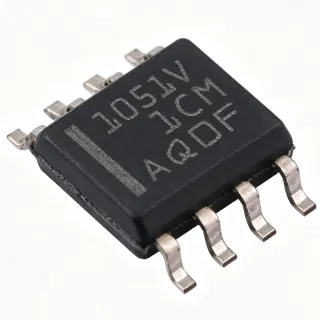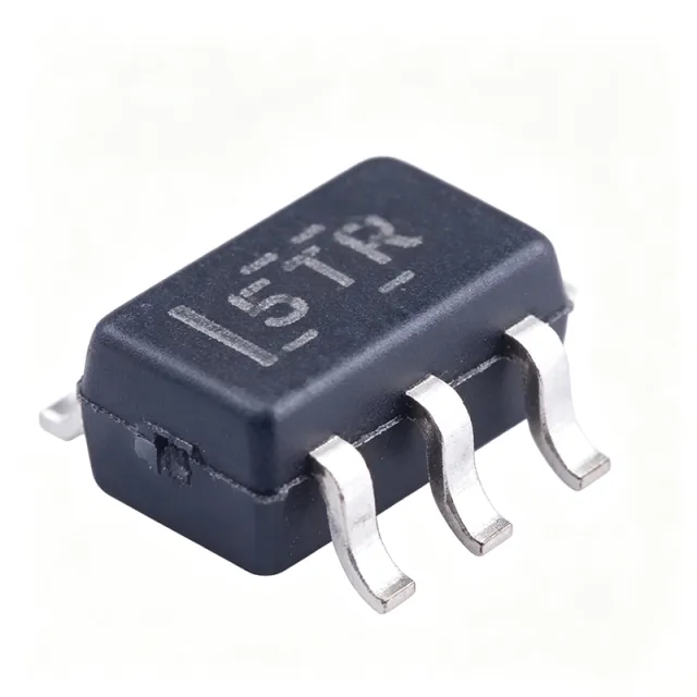
SN65HVD255QDRQ1 - 3.3V Turbo CAN Transceiver Q1 | TI
部品番号: SN65HVD255QDRQ1 ✓ 生産中| 数量 | 単価 | 小計 |
|---|---|---|
| 1 | $1.39 | $1.39 |
| 10 | $1.32 | $13.20 |
| 100 | $1.18 | $118.00 |
| 500 | $1.05 | $525.00 |
| 1,000 | $0.94 | $940.00 |
SN65HVD255QDRQ1 概要
A CAN transceiver is a physical-layer interface device that converts the single-ended TTL logic levels of a CAN protocol controller into the differential signaling on a twisted-pair CAN bus, and back again at the receiver. Within the interface IC hierarchy, it sits between the CAN controller (often integrated in an MCU) and the two-wire physical bus, providing dominant/recessive driving, bus fault protection, and receiver filtering.
Key features include turbo-mode operation supporting data rates beyond 1 Mbps on short networks, enhanced loop-time symmetry for large and heavily loaded networks, single-supply 3.3V operation, and ISO 11898 physical-layer compatibility. The device integrates short-circuit protection, thermal shutdown, and wide common-mode bus voltage tolerance for robust operation in harsh electrical environments.
The proprietary transceiver architecture of the SN65HVD25x Turbo family delivers fast loop times that improve arbitration success and bit-timing margin in highly loaded network nodes, distinguishing it from standard 1 Mbps transceivers. Receiver input impedance and bus biasing are optimized for large networks with many nodes, and the family datasheet (Rev. D) adds features oriented toward functional safety. The RS pin selects between slope-control and high-speed (turbo) operation, letting one design cover both EMC-sensitive and maximum-speed segments.
Typical applications include automotive body electronics and gateway nodes, industrial PLC and motor-control CAN networks running at 3.3V logic, and high-data-rate buses where standard transceivers cannot sustain signal integrity above 1 Mbps.
Design tip: size the bus termination at 120 ohms, verify dominant-state current limits when operating in turbo mode, and place a 0.1 uF local decoupling capacitor at VCC.
This page synthesizes verified distributor pricing, drop-in alternatives, pinout data, and practical design notes not found in the manufacturer datasheet alone. Prices referenced as of 2026-09-01.
ドロップイン代替品: SN65HVD255QDRQ1 — 同一パッケージでピン互換。PCBの作り直しが必要な異なるパッケージの部品は除外されています。
このシリーズのバリエーション
同一シリーズでドロップイン互換のモデル: SN65HVD255QDRQ1 (同一形状・フットプリント) — 相違点: Package, Data Rate, Function, Protocol, Supply Voltage.
クイック比較ツール — 並列比較する代替部品を選択:
SN65HVD256QDRQ1
✅ ドロップイン ⚠️ 仕様未検証📋 参考代替品(カタログ未掲載)
SN65HVD230QDRQ1
✅ ドロップイン ⚠️ 仕様未検証✓ 在庫あり
$1.11 / 個
データシートを見る →SN65HVD234QDRQ1
✅ ドロップイン ⚠️ 仕様未検証✓ 在庫あり
$0.98 / 個
データシートを見る →SN65HVD255DR
✅ ドロップイン✓ 在庫あり
$1.12 / 個
データシートを見る →TJA1051T/3/1
✅ ドロップイン✓ 在庫あり
$0.4102 / 個
データシートを見る →TCAN337G
✅ ドロップイン ⚠️ 仕様未検証✓ 在庫あり
$0.55 / 個
データシートを見る →SN65HVD255QDRQ1 仕様
| 機能 | Turbo CAN Transceiver |
| 電源電圧 | 3.3 V |
| データレート | >1 Mbps (turbo mode) |
| Protocol | ISO 11898 compatible CAN |
| Duplex | Half-duplex |
| Number of Transceivers | 1 |
| パッケージ | SOIC-8 (D) |
| 実装タイプ | Surface Mount |
| Automotive Qualification | AEC-Q100 Qualified |
| Short-Circuit Protection | Yes |
| 熱シャットダウン | Yes |
| Mode Select | RS pin (slope control / high speed) |
| Family | SN65HVD25x Turbo CAN |
SN65HVD255QDRQ1 ピン構成
| ピン 1 | TXD — Transmit data input from CAN controller (dominant low) |
| ピン 2 | GND — Ground |
| ピン 3 | VCC — 3.3 V supply |
| ピン 4 | RXD — Receive data output to CAN controller |
| ピン 5 | VREF — VCC/2 reference voltage output |
| ピン 6 | CANL — CAN low differential bus line |
| ピン 7 | CANH — CAN high differential bus line |
| ピン 8 | RS — Slope-control / high-speed mode select |
主な用途
SN65HVD255QDRQ1 の用途: 6 件s: Automotive Body Electronics and Gateway Nodes, Industrial PLC and Motor Control CAN Networks, High-Data-Rate CAN Backbones and Fast Buses, 3.3 V Logic Embedded Systems, Battery Management and E-Mobility Communication, Elevator, HVAC and Building Automation Buses.
Automotive Body Electronics and Gateway Nodes
The SN65HVD255QDRQ1 is AEC-Q100 qualified with automotive-grade traceability, making it a natural fit for body-control modules and CAN gateway nodes where multi-bus loading and heavy arbitration traffic are routine. Its fast loop times and turbo-mode capability above 1 Mbps improve bit-timing margin when many nodes share a segment, reducing arbitration retries that degrade response latency in body networks. Placed between the 3.3 V MCU CAN controller and the twisted-pair bus with 120-ohm split termination, it drives CANH/CANL directly while its short-circuit protection and thermal shutdown guard against wiring-harness faults. The RS pin allows slope-controlled operation for EMC-sensitive zones and high-speed mode on backbone segments.
おすすめ
Industrial PLC and Motor Control CAN Networks
Industrial CAN networks in PLCs and motor-control systems run in electrically noisy environments with long bus runs and many nodes. The SN65HVD255QDRQ1's 3.3 V single-supply operation interfaces directly with modern 3.3 V MCUs without level shifting, while its wide common-mode bus tolerance and short-circuit protection withstand industrial ground-potential differences and wiring faults. Fast loop times improve arbitration on heavily loaded factory-floor segments, and thermal shutdown protects against sustained bus shorts. Design practice: use RS-pin slope control near VFDs and drives to limit EMI, terminate each bus end at 120 ohms, and verify dominant-state current limits when running turbo rates above 1 Mbps per the TI SN65HVD25x datasheet (Rev. D).
おすすめ
High-Data-Rate CAN Backbones and Fast Buses
For network segments where classical 1 Mbps transceivers cannot sustain signal integrity, the SN65HVD255QDRQ1's turbo mode delivers data rates in excess of 1 Mbps on short networks, and its enhanced loop-time symmetry preserves usable data rates even on large, heavily loaded buses. This makes it suited to fast CAN backbones in vehicles and machines that aggregate traffic from many sub-nodes. Implementation places the transceiver between the CAN controller and a short, impedance-controlled 120-ohm differential backbone; the high-speed RS configuration minimizes propagation delay. Trade-off: turbo mode increases electromagnetic emissions versus slope-controlled mode, so EMI budgets must be validated on the final harness.
おすすめ
3.3 V Logic Embedded Systems
Many modern MCUs integrate a CAN controller operating at 3.3 V I/O levels. The SN65HVD255QDRQ1 runs from the same 3.3 V rail, eliminating level shifters and a separate 5 V supply that 5 V-only transceivers such as the TJA1051T would require. This reduces board area, power-tree complexity, and cost in cost-optimized embedded nodes. The device's RS pin, TXD/RXD interface, and VREF output integrate cleanly into typical 3.3 V microcontroller reference designs. Design practice: keep a 0.1 uF decoupling capacitor within 2 mm of VCC, route TXD and RXD as short single-ended traces, and confirm the MCU's CAN timing registers are configured for the transceiver's fast loop times when operating in turbo mode.
おすすめ
Battery Management and E-Mobility Communication
Battery management systems and e-mobility controllers commonly use CAN to report cell data and fault states to vehicle ECUs. The SN65HVD255QDRQ1's AEC-Q100 qualification supports these automotive-adjacent environments, while its 3.3 V operation matches the low-voltage digital domain of BMS front-end ICs. Fast loop times ensure timely fault propagation on heavily loaded vehicle buses where many nodes transmit simultaneously. Implementation notes: in high-voltage battery packs the transceiver typically sits behind a digital isolator for galvanic isolation between the pack domain and the chassis CAN bus; the RS pin should be configured per the vehicle OEM's EMC specification, and short-circuit protection guards against harness chafe faults common in traction environments.
おすすめ
Elevator, HVAC and Building Automation Buses
Building automation systems - elevator controllers, HVAC air-handling units, and fire/safety panels - use CAN segments with long cable runs and dozens of nodes, creating exactly the heavily loaded network conditions the SN65HVD255QDRQ1 was designed for. Its receiver input impedance and bus biasing are optimized for large node counts, and fast loop times keep arbitration efficient as node count grows. The 3.3 V supply simplifies integration with modern building-controller MCUs, and slope-controlled RS mode tames EMI on unshielded building wiring. Practical layout: maintain a single daisy-chain topology with 120-ohm termination at both physical ends, avoid star topologies that create reflections, and verify bus bias behavior with all nodes in standby per the TI SN65HVD25x datasheet.
おすすめ
おすすめ製品の概要
エンジニアリング参考データ: SN65HVD255QDRQ1 — 比較、設計ガイダンス、コンプライアンス情報。
選定ガイド
代替品との比較
| パラメータ | この製品 | SN65HVD256QDRQ1 | SN65HVD230QDRQ1 | SN65HVD255DR | TJA1051T/3/1 | TCAN337G |
|---|---|---|---|---|---|---|
| Package | SOIC-8 (D) | SOIC-8 (D) - same | SOIC-8 (D) - same | SOIC-8 (D) - same | SOIC-8 (D) - same | SOIC-8 (D) - same |
| Brand | Texas Instruments | Texas Instruments | Texas Instruments | Texas Instruments | NXP Semiconductors | Texas Instruments |
| Supply Voltage | 3.3 V | 3.3 V | 3.3 V | 3.3 V | 5 V (3.3 V-tolerant I/O) | 3.3 V |
| Max Data Rate | >1 Mbps (turbo) | >1 Mbps (turbo) | 1 Mbps | >1 Mbps (turbo) | 1 Mbps (classical CAN) | 5 Mbps (CAN FD) |
| Protocol Support | Classical CAN (ISO 11898) | Classical CAN (ISO 11898) | Classical CAN (ISO 11898) | Classical CAN (ISO 11898) | Classical CAN (ISO 11898) | CAN FD |
| Mode Control | RS pin (slope control / high speed) | RS pin | RS + EN pins | RS pin | STB pin (standby) | S pin / silent mode |
主な差別化要因
- Turbo-mode data rates above 1 Mbps (vs SN65HVD230QDRQ1)
- True 3.3 V single-supply operation (vs TJA1051T/3/1)
- Automotive grade with turbo speed combination (vs SN65HVD255DR)
- Classical CAN cost advantage over CAN FD (vs TCAN337G)
設計ノート
Place a 0.1 uF ceramic decoupling capacitor within 2 mm of VCC (pin 3) to GND (pin 2), plus a 1-10 uF bulk capacitor per board. Route CANH (pin 7) and CANL (pin 6) as a tightly coupled differential pair, and terminate the bus at both physical ends with 120 ohms. Keep TXD/RXD traces short and away from the bus lines to prevent coupling transients into the controller interface.
The RS pin (pin 8) is your primary EMI tool. In EMC-sensitive zones (near motors, VFDs, antenna modules), connect RS through a resistor to ground to enable slope control, reducing CANH/CANL slew rates at the cost of max bus length/speed. On backbone segments where data rate above 1 Mbps is required, tie RS to VCC for high-speed turbo mode. Validate radiated emissions on the final harness, because turbo mode increases edge-driven emissions versus slope-controlled mode.
Turbo-mode operation above 1 Mbps is intended for short networks; do not assume ISO 11898 max-bus-length figures apply. Estimated: bus length must shrink proportionally with bit rate - at 2 Mbps, bit time halves versus 1 Mbps, roughly halving the allowable cable length for a given propagation margin. Also verify dominant-state current limits and thermal behavior under sustained bus faults (the device has thermal shutdown, but repeated fault cycling degrades reliability), and confirm VREF (pin 5) loading assumptions if a receiver reference divider uses it.
コンプライアンス情報
AEC-Q100 qualified per the QDRQ1 suffix and TI product page. RoHS/REACH/lead-free status not stated in provided data - verify on TI.com product page.