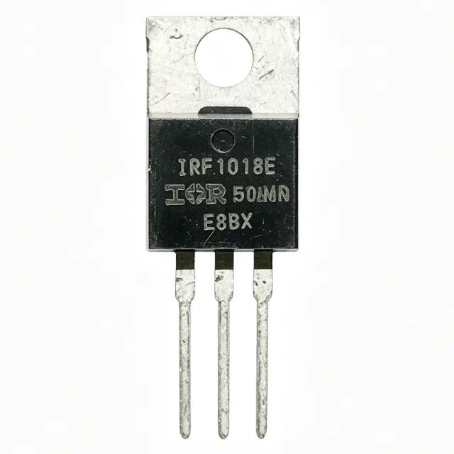
IRF1018EPBF - 60V 79A 8.4mOhm N-Ch HEXFET MOSFET | Infineon
부품 번호: IRF1018EPBF ✓ 활성| 수량 | 단가 | 합계 |
|---|---|---|
| 1 | $0.85 | $0.85 |
| 10 | $0.72 | $7.20 |
| 100 | $0.58 | $58.00 |
| 500 | $0.46 | $230.00 |
| 1,000 | $0.38 | $380.00 |
IRF1018EPBF 개요
A power MOSFET (Metal-Oxide-Semiconductor Field-Effect Transistor) is a voltage-controlled semiconductor switch used to efficiently commutate current between the drain and source terminals. Power MOSFETs belong to the broader family of discrete transistors, which sit under discrete semiconductors and ultimately the semiconductor device hierarchy. N-channel enhancement-mode MOSFETs like the IRF1018EPBF are the dominant switch choice for low-voltage (<=100 V) synchronous rectification, low-side buck switches, and DC motor control because they offer fast switching, simple gate drive (10 V typical), and low conduction loss. Compared with P-channel MOSFETs and bipolar junction transistors (BJTs), N-channel MOSFETs deliver lower Rds(on) per unit silicon area and require only a positive gate-source voltage to turn on.
Key features include 8.4 mOhm Rds(on) at Vgs=10 V, 46 nC total gate charge (Qg), and a maximum continuous drain current of 79 A at 25 C case temperature. The TO-220AB package is rated for 110 W power dissipation at Tc=25 C and provides a thermal resistance (junction-to-case) suitable for attaching a clip-on or PCB-mounted heatsink. The device is optimized for 10 V Vgs drive, which simplifies interface to standard gate-driver ICs and most microcontrollers with logic-level PWM outputs.
Technically, the IRF1018EPBF uses Infineon's proprietary HEXFET silicon trench technology, which achieves low specific on-resistance (Rds(on) x area) and high avalanche ruggedness. Its low Qg (46 nC) and Qgd values reduce switching losses and enable operation above 100 kHz in synchronous-rectifier positions. The optimized body diode supports continuous-conduction-mode (CCM) PFC and synchronous-buck topologies without requiring an external anti-parallel diode.
Typical applications include high-efficiency synchronous rectification in server and telecom SMPS, low-side switch in DC-DC buck converters, brushless DC (BLDC) motor drives, Class-D audio output stages, industrial PWM motor control, and battery protection/load switching in 12 V/24 V systems. The 60 V rating also provides ample margin for 48 V telecom rails and transient-prone automotive 24 V environments.
When designing with the IRF1018EPBF, ensure adequate heatsinking at high continuous current: at 79 A the device dissipates roughly 52 W (I^2 * Rds(on)) and the TO-220AB junction-to-ambient thermal resistance typically forces a clip-on heatsink for sustained operation above 30 A. A 10 V gate drive is required; logic-level (4.5 V) gate drive will substantially raise Rds(on) and is not recommended.
This page synthesizes distributor pricing, drop-in alternatives from same-brand and cross-brand sources, and practical design notes not found in the manufacturer datasheet alone.
드롭인 대체품: IRF1018EPBF — 동일 패키지, 핀 호환. PCB 재작업이 필요한 다른 패키지 부품은 제외됩니다.
이 시리즈의 변형
다음과 드롭인 호환되는 동일 시리즈 모델: IRF1018EPBF (동일 폼 팩터 및 풋프린트) — 차이점: Mounting Type, RoHS Status, FET Type, Package, Technology.
빠른 비교 도구 — 나란히 비교할 대체 부품을 선택하십시오:
IRFB3207ZPBF
✓ 재고 있음
$1.62 / 개
데이터시트 보기 →IRF1407PBF
✓ 재고 있음
$0.86 / 개
데이터시트 보기 →IRL3705NPBF
✓ 재고 있음
$0.92 / 개
데이터시트 보기 →IRFB3077PBF
📋 참조 대체품 (카탈로그에 없음)
IRF3205PBF
📋 참조 대체품 (카탈로그에 없음)
STP55NF06L
📋 참조 대체품 (카탈로그에 없음)
IRF1018EPBF 최대 정격 & 전기적 특성
| FET Type | N-Channel |
| Technology | HEXFET (Power MOSFET) |
| Drain-Source Voltage (Vdss) | 60 V |
| Continuous Drain Current (Id) at Tc=25C | 79 A |
| Rds(on) max at Vgs=10V | 8.4 mOhm |
| Total Gate Charge (Qg) | 46 nC |
| Gate Drive Voltage (Vgs) | 10 V (optimized; +/-20 V max) |
| Power Dissipation (Pd) at Tc=25C | 110 W |
| 동작 온도 범위 | -55 C to +175 C (Tj) |
| 패키지 | TO-220AB (through-hole, 3-lead) |
| 실장 유형 | Through Hole |
| Qualification | JEDEC (Industrial market) |
| RoHS 상태 | Compliant |
| Lead-Free (PBF suffix) | Yes |
| 핀 수 | 3 (Gate, Drain, Source) |
IRF1018EPBF 핀 구성
| 핀 1 | Gate — Gate drive input; 10V Vgs typical for full enhancement |
| 핀 2 | Drain — Drain terminal; also connected to the metal tab |
| 핀 3 | Source — Source terminal; power-ground return |
안전 동작 영역 (DC, Tj=25C)
일반적인 애플리케이션
IRF1018EPBF 적합 용도: 7 애플리케이션s: Synchronous Rectification in SMPS, Low-Side Switch in DC-DC Buck Converters, Brushless DC (BLDC) Motor Drive, Class-D Audio Output Stage, Industrial PWM Motor Control, Battery Protection and Load Switching, Solar Charge Controller / MPPT Switch.
Synchronous Rectification in SMPS
The IRF1018EPBF is engineered for synchronous-rectifier positions in switched-mode power supplies where it replaces lossy Schottky diodes on the secondary side of an isolated converter. Its 8.4 mOhm Rds(on) at Vgs=10V and 46 nC total gate charge reduce both conduction and switching losses, delivering 1-3% efficiency gains over Schottky-only designs at full load. In a typical 12V/30A server SMPS, two IRF1018EPBF devices in a center-tapped rectifier dissipate substantially less heat than the equivalent Schottky pair, allowing smaller heatsinks or eliminating forced-air cooling. The 60V Vds provides ample margin for 48V-input telecom rails and reflected voltage transients.
추천
Low-Side Switch in DC-DC Buck Converters
As a low-side (ground-referenced) switch in buck converters, the IRF1018EPBF benefits from its N-channel construction, 60V Vds rating, and 8.4 mOhm Rds(on). In a 24V-to-12V/20A buck stage the device sees only Vds=VIN plus ringing, well within its 60V envelope. Its 46 nC Qg is low enough to support 200-500 kHz switching with IR2104 or IR2117 gate drivers, keeping switching losses under 2W at full load. Compared with a Schottky catch diode, a synchronous IRF1018EPBF boosts efficiency by 5-8 percentage points and improves thermal performance in compact industrial supplies.
추천
Brushless DC (BLDC) Motor Drive
The IRF1018EPBF serves well as the low-side or high-side switch in BLDC motor drive inverters rated up to 60V bus and 50-60A continuous phase current. Its 8.4 mOhm Rds(on) minimizes I^2R losses during PWM commutation, while its 175C maximum junction temperature supports sustained high-current operation with a clip-on heatsink. In a 48V/3kW e-bike or industrial pump drive, three half-bridges using IRF1018EPBF deliver >96% inverter efficiency. The TO-220AB package simplifies PCB layout and heatsink attachment compared with D2PAK surface-mount alternatives.
추천
Class-D Audio Output Stage
In half-bridge Class-D audio amplifiers, the IRF1018EPBF functions as a switching output device delivering high current transients to a low-pass LC filter and loudspeaker load. Its 46 nC Qg and fast body-diode recovery support 250-500 kHz PWM switching with low dead-time distortion. A pair of IRF1018EPBF in a 200W mono amplifier module provides ample current headroom for 4-ohm loads while maintaining low THD+N. Designers should add gate-source Zener clamps to protect against Miller-induced Vgs spikes during bridge switching.
추천
Industrial PWM Motor Control
The IRF1018EPBF is well-suited to industrial PWM motor speed controllers operating from 24V/36V/48V DC buses. Its 60V Vds rating tolerates voltage spikes from motor inductance and provides headroom for 48V industrial bus systems. With 79A continuous current capability and 8.4 mOhm Rds(on), it handles motor stall currents of 150-200A (pulsed) without failure. The HEXFET silicon ensures avalanche ruggedness during regenerative braking events. Its through-hole TO-220AB package enables screw-attached heatsinks for harsh industrial environments.
추천
Battery Protection and Load Switching
The IRF1018EPBF operates as a low-side disconnect switch in 12V/24V battery management systems (BMS) and load-switching applications. With 8.4 mOhm Rds(on), the voltage drop at 30A continuous load is only 0.25V, minimizing parasitic losses in e-scooter, solar, and telecom battery systems. Its 60V Vds provides generous margin for transient voltages on automotive 24V or solar MPPT buses. The TO-220AB package is field-replaceable and accepts standard insulated thermal pads for chassis-mount heatsinking in outdoor enclosures.
추천
Solar Charge Controller / MPPT Switch
In MPPT solar charge controllers, the IRF1018EPBF operates as the main buck or buck-boost switching element between the PV panel and battery bus. Its 60V Vds handles 24V-panel Voc transients with safety margin, while 8.4 mOhm Rds(on) maximizes conversion efficiency (>97%) in 20-40A charge controllers. The TO-220AB package dissipates switching and conduction losses into a clip-on heatsink without forced-air cooling. Combined with a microcontroller-driven MPPT algorithm, two IRF1018EPBF devices (high-side and low-side) implement a complete synchronous buck stage.
추천
추천 제품 요약
엔지니어링 참조 데이터: IRF1018EPBF — 비교, 설계 지침 및 규정 준수 정보.
선택 가이드
대체품과의 비교
| 파라미터 | 이 제품 | IRFB3207ZPBF | IRFB3077PBF | IRF1407PBF | IRF3205PBF | IRL3705NPBF | STP55NF06L |
|---|---|---|---|---|---|---|---|
| Package | TO-220AB | TO-220AB - same | TO-220AB - same | TO-220AB - same | TO-220AB - same | TO-220AB - same | TO-220AB - same |
| Brand | Infineon | Infineon (same brand) | Infineon (same brand) | Infineon (same brand) | Infineon (same brand) | Infineon (same brand) | STMicroelectronics (cross-brand) |
| Drain-Source Voltage (Vdss) | 60 V | 75 V | 75 V | 75 V | 55 V | 55 V | 60 V |
| Continuous Drain Current (Id) | 79 A | 75 A | 210 A (pulsed) | 130 A (pulsed) | 110 A (pulsed) | 89 A | 50 A |
| Rds(on) at Vgs=10V | 8.4 mOhm | 8.3 mOhm | 3.3 mOhm | 7.8 mOhm | 8.0 mOhm | 10 mOhm | 18 mOhm |
| Gate Drive Type | Standard (10V Vgs) | Standard (10V Vgs) | Standard (10V Vgs) | Standard (10V Vgs) | Standard (10V Vgs) | Logic-level (4V Vgs) | Logic-level (5V Vgs) |
주요 차별점
- Lower Rds(on) than IRF3205 within the same TO-220AB family (vs IRF3205PBF)
- Lower Vds thresh and cleaner drive than logic-level IRL3705 (vs IRL3705NPBF)
- Significantly lower Rds(on) than STP55NF06L cross-brand (vs STP55NF06L)
설계 노트
Estimated: At continuous 79 A load with Rds(on) = 8.4 mOhm, conduction loss is approximately 79^2 * 0.0084 = 52 W. The TO-220AB junction-to-ambient thermal resistance (theta_JA) without heatsink is around 62 C/W, which would push Tj well past the 175 C maximum. A clip-on heatsink with theta_SA <= 5 C/W (for example, an Aavid 577202B00000G with 100 LFM airflow) is mandatory for sustained full-current operation. Always size the heatsink so that Tc stays below 100 C in the worst-case ambient.
Use a single-side copper pour of at least 2 square inches connected to the drain tab to spread heat to the PCB. Keep gate-drive traces short and add a 10 ohm gate resistor to dampen ringing from the gate-source capacitance combined with package lead inductance. Place a 100 ohm resistor plus 10 kohm pull-down between gate and source to ensure the MOSFET stays off when the gate driver is tri-stated during power-up. Add a TVS diode across drain-source for inductive load switching (e.g., 5.0SMDJ60CA for 60 V clamp).
Do NOT drive the IRF1018EPBF with logic-level 3.3V or 5V GPIO - the threshold voltage is typically 2-4V and the device is only partially enhanced at 5V, which causes high Rds(on) and thermal runaway. Use a dedicated gate driver (e.g., IR2104STRPBF) that produces a clean 10V Vgs signal. Also avoid operating continuously at the absolute maximum Id of 79A - derate to 50-60A continuous for reliable long-term operation. Watch for Vds ringing above 60V in hard-switched inductive applications; use snubber or TVS.
Minimize the high-current loop area between the MOSFET, the input capacitor, and the freewheeling diode (or low-side synchronous FET). This loop carries di/dt of hundreds of amps per microsecond during switching and parasitic inductance of even 10 nH will create Vds overshoot spikes that may exceed 60V. Use a ground-return plane directly under the loop. For through-hole TO-220AB, bend the leads vertically and place the input capacitor on the same side of the PCB to minimize lead length.
규정 준수 정보
PBF suffix indicates lead-free, RoHS-compliant. Qualified to JEDEC standards for the Industrial market per Infineon datasheet. Not AEC-Q100 qualified - for automotive designs, use Infineon IRF1018E (automotive grade) variants or dedicated automotive MOSFETs.

