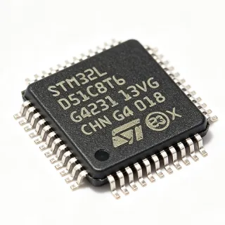
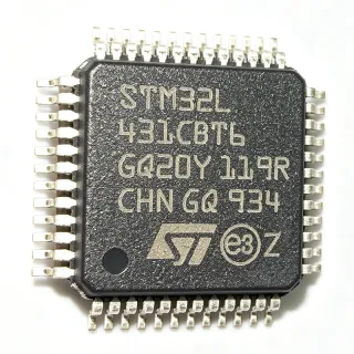
STM32G491CET6 - 170MHz ARM Cortex-M4F MCU | STMicroelectronics
MPN: STM32G491CET6 ✓ Active| Qty | Unit Price | Extended |
|---|---|---|
| 1 | $6.5 | $6.50 |
| 10 | $5.85 | $58.50 |
| 100 | $5.2 | $520.00 |
| 500 | $4.68 | $2,340.00 |
| 1,000 | $4.16 | $4,160.00 |
STM32G491CET6 Overview
What is a microcontroller? A microcontroller (MCU) is a compact integrated circuit designed to govern a specific operation in an embedded system. It contains a processor core, memory (Flash and RAM), and programmable input/output peripherals on a single chip. Microcontrollers are the brains of countless electronic devices, from automotive engine control units to home appliances and IoT sensors. In the system hierarchy, a microcontroller sits between a microprocessor (which requires external memory and peripherals) and a system-on-chip (SoC, which integrates more complex functions like graphics or wireless). The STM32G491CET6 is a mid-range MCU that balances performance, power efficiency, and peripheral integration.
Key features of the STM32G491CET6 include a 170 MHz ARM Cortex-M4F core with DSP instructions and FPU, 512 KB of Flash memory, 112 KB of SRAM, and a comprehensive set of peripherals. It features a high-resolution timer (HRTIM) capable of generating PWM signals with sub-nanosecond resolution, essential for digital power conversion. The device also includes a 12-bit ADC with hardware oversampling, multiple 12-bit DACs, comparators, and operational amplifiers, making it suitable for analog-intensive applications. Communication interfaces include SPI, I2C, USART, and CAN FD, providing robust connectivity options.
From a technical depth perspective, the STM32G491CET6 leverages the ARM Cortex-M4F architecture with a single-precision FPU and DSP instructions, enabling efficient execution of complex algorithms such as FFT and motor control loops. The high-resolution timer (HRTIM) is a standout feature, offering up to 184 picoseconds resolution, which is critical for high-frequency switching power supplies. The device also integrates a CORDIC hardware accelerator for trigonometric functions and a filter math accelerator (FMAC) for digital filtering, offloading the CPU for real-time control tasks.
Typical applications include field-oriented control (FOC) of brushless DC motors, digital power supplies (buck, boost, flyback), solar inverters, and industrial automation. The combination of high-speed ADC, comparators, and HRTIM makes it ideal for closed-loop control systems requiring precise timing and fast response. Additionally, its CAN FD interface supports robust communication in automotive and industrial networks.
When designing with the STM32G491CET6, ensure proper decoupling of the power supply pins with 100 nF capacitors placed close to each VDD pin. The VDDA analog supply should be filtered with a ferrite bead and a 1 uF capacitor to minimize noise on analog peripherals. For high-resolution timer applications, use a clean clock source and minimize PCB trace inductance in the power stage.
Drop-in alternatives for STM32G491CET6 — same package, pin-to-pin compatible. Different-package parts requiring PCB rework are excluded.
Variants in this series
Same-series models that are drop-in compatible with STM32G491CET6 (same form factor and footprint) — differing in ADC, DAC, High-Resolution Timer, Package, SRAM.
Quick Comparison Tool — Select alternative parts for side-by-side comparison:
STM32G491CCT6
✅ Drop-In ⚠️ Specs Unverified📋 Reference alternative (not in catalog)
STM32G431CET6
✅ Drop-In ⚠️ Specs Unverified📋 Reference alternative (not in catalog)
STM32G474CET6
✅ Drop-In ⚠️ Specs Unverified✓ In Stock
$5.94 / Unit
View Datasheet →STM32G491CET6 Maximum Ratings & Electrical Characteristics
| Core | ARM Cortex-M4F with FPU |
| Maximum Clock Speed | 170 MHz |
| Flash Memory | 512 KB |
| SRAM | 112 KB |
| Package | LQFP-48 (7x7 mm) |
| Supply Voltage | 1.71 V to 3.6 V |
| Operating Temperature | -40C to +85C |
| GPIO Pins | 36 |
| ADC | 2x 12-bit, 5 MSPS |
| DAC | 3x 12-bit |
| High-Resolution Timer | 1x 184 ps resolution |
| Advanced Timers | 4x 16-bit |
| Communication Interfaces | SPI, I2C, USART, CAN FD |
| DMA | 2x 8-channel |
| RoHS Status | Compliant |
STM32G491CET6 Pin Configuration
| Pin 1 | VBAT — Battery backup supply for RTC |
| Pin 2 | PC13 — GPIO or RTC output |
| Pin 3 | PC14 — GPIO or OSC32_IN |
| Pin 4 | PC15 — GPIO or OSC32_OUT |
| Pin 5 | PF0 — GPIO |
| Pin 6 | PF1 — GPIO |
| Pin 7 | NRST — Reset (active low) |
| Pin 8 | VSSA — Analog ground |
| Pin 9 | VDDA — Analog power supply |
| Pin 10 | PA0 — GPIO/ADC |
| Pin 11 | PA1 — GPIO/ADC |
| Pin 12 | PA2 — GPIO/USART2_TX |
| Pin 13 | PA3 — GPIO/USART2_RX |
| Pin 14 | PA4 — GPIO/SPI1_NSS |
| Pin 15 | PA5 — GPIO/SPI1_SCK |
| Pin 16 | PA6 — GPIO/SPI1_MISO |
| Pin 17 | PA7 — GPIO/SPI1_MOSI |
| Pin 18 | PB0 — GPIO/ADC |
| Pin 19 | PB1 — GPIO/ADC |
| Pin 20 | PB2 — GPIO |
| Pin 21 | PB10 — GPIO/I2C2_SCL |
| Pin 22 | PB11 — GPIO/I2C2_SDA |
| Pin 23 | PB12 — GPIO/SPI2_NSS |
| Pin 24 | PB13 — GPIO/SPI2_SCK |
| Pin 25 | PB14 — GPIO/SPI2_MISO |
| Pin 26 | PB15 — GPIO/SPI2_MOSI |
| Pin 27 | PC6 — GPIO/TIM3_CH1 |
| Pin 28 | PC7 — GPIO/TIM3_CH2 |
| Pin 29 | PC8 — GPIO/TIM3_CH3 |
| Pin 30 | PC9 — GPIO/TIM3_CH4 |
| Pin 31 | PA8 — GPIO/TIM1_CH1 |
| Pin 32 | PA9 — GPIO/USART1_TX |
| Pin 33 | PA10 — GPIO/USART1_RX |
| Pin 34 | PA11 — GPIO/USB_DM |
| Pin 35 | PA12 — GPIO/USB_DP |
| Pin 36 | PA13 — SWDIO |
| Pin 37 | PA14 — SWCLK |
| Pin 38 | PA15 — GPIO/JTDI |
| Pin 39 | PB3 — GPIO/JTDO |
| Pin 40 | PB4 — GPIO/NJTRST |
| Pin 41 | PB5 — GPIO |
| Pin 42 | PB6 — GPIO/I2C1_SCL |
| Pin 43 | PB7 — GPIO/I2C1_SDA |
| Pin 44 | BOOT0 — Boot mode selection |
| Pin 45 | PB8 — GPIO/CAN_RX |
| Pin 46 | PB9 — GPIO/CAN_TX |
| Pin 47 | VSS — Ground |
| Pin 48 | VDD — Power supply |
Typical Applications
STM32G491CET6 is suitable for 6 applications: Field-Oriented Control (FOC) of Brushless DC Motors, Digital Power Supplies (Buck, Boost, Flyback), Solar Inverters, Industrial Automation and Control, Electric Vehicle (EV) Charging Stations, Robotics and Drones.
Field-Oriented Control (FOC) of Brushless DC Motors
The STM32G491CET6 is ideal for FOC of BLDC motors due to its high-resolution timer (HRTIM) with 184 ps resolution, enabling precise PWM generation. The 12-bit ADCs with 5 MSPS sampling rate allow fast and accurate current sensing. The Cortex-M4F core with FPU accelerates the complex mathematical computations required for FOC algorithms, such as Clarke and Park transforms. In a typical application, the MCU reads phase currents via shunt resistors, processes them through the ADC, and generates PWM signals to drive the inverter. The HRTIM's high resolution minimizes torque ripple and improves efficiency. Additionally, the built-in comparators can be used for overcurrent protection, ensuring safe operation. The device's 170 MHz clock speed ensures real-time control loop execution at high switching frequencies, making it suitable for applications like drones, electric vehicles, and industrial servo drives.
Recommended
Digital Power Supplies (Buck, Boost, Flyback)
The STM32G491CET6 excels in digital power conversion due to its high-resolution timer (HRTIM) with 184 ps resolution, which is essential for precise PWM control in switching power supplies. The fast ADC (5 MSPS) enables real-time voltage and current monitoring, allowing implementation of advanced control algorithms like peak current mode control or voltage mode control with digital compensation. The device's comparators can be used for cycle-by-cycle current limiting, protecting the power stage. In a typical digital power supply, the MCU reads the output voltage and inductor current, computes the duty cycle using a PID controller, and updates the HRTIM registers. The 170 MHz clock ensures fast loop response, improving transient performance. The STM32G491CET6 also includes a CORDIC accelerator for trigonometric functions, which can be used in power factor correction (PFC) algorithms. This makes it suitable for applications like server power supplies, LED drivers, and battery chargers.
Recommended
Solar Inverters
The STM32G491CET6 is well-suited for solar inverters, where it manages maximum power point tracking (MPPT) and DC-AC conversion. The high-resolution timer (HRTIM) generates high-frequency PWM signals for the inverter bridge, while the fast ADC monitors solar panel voltage and current to optimize power extraction. The Cortex-M4F core with FPU handles complex MPPT algorithms, such as perturb and observe or incremental conductance. The device's multiple ADCs allow simultaneous sampling of multiple channels, improving accuracy. In a typical solar inverter, the MCU controls the boost converter to step up the panel voltage and the H-bridge inverter to produce AC output. The HRTIM's 184 ps resolution ensures low total harmonic distortion (THD) in the output waveform. The STM32G491CET6's robust communication interfaces, including CAN FD, enable integration with monitoring systems. This makes it ideal for residential and commercial solar power systems.
Recommended
Industrial Automation and Control
The STM32G491CET6 is a versatile MCU for industrial automation, offering a rich set of peripherals including multiple timers, ADCs, DACs, and communication interfaces. It can be used in PLCs, motor drives, and robotic controllers. The 170 MHz Cortex-M4F core provides ample processing power for real-time control and communication protocols. The device's CAN FD interface supports high-speed industrial networks, while the UART, SPI, and I2C interfaces enable connectivity to sensors, actuators, and displays. The high-resolution timer can generate precise PWM for controlling valves or heaters. The multiple ADCs allow simultaneous monitoring of various analog signals, such as temperature and pressure. In a typical industrial controller, the MCU reads sensor data, executes control algorithms, and drives outputs via PWM or digital I/O. The STM32G491CET6's robust design, with operating temperature range of -40C to +85C, ensures reliable operation in harsh environments.
Recommended
Electric Vehicle (EV) Charging Stations
The STM32G491CET6 is suitable for EV charging stations, where it manages power conversion and communication. The high-resolution timer (HRTIM) enables precise control of the AC-DC and DC-DC converters, ensuring efficient charging. The fast ADC monitors voltage and current to implement safety features like overcurrent and overvoltage protection. The device's CAN FD interface allows communication with the vehicle's battery management system (BMS) and the charging network. In a typical charging station, the MCU controls the power stage to deliver the required charging profile (e.g., CC-CV), while monitoring the charging process. The Cortex-M4F core with FPU handles complex control algorithms and communication protocols. The STM32G491CET6's multiple communication interfaces (UART, SPI, I2C, CAN) enable integration with user interfaces and remote monitoring. Its robust design and wide operating temperature range make it ideal for outdoor installations.
Recommended
Robotics and Drones
The STM32G491CET6 is an excellent choice for robotics and drones, providing high-performance processing and precise motor control. The 170 MHz Cortex-M4F core with FPU handles complex algorithms like sensor fusion and path planning. The high-resolution timer (HRTIM) generates precise PWM signals for brushless DC motors, enabling smooth and efficient flight. The multiple ADCs allow simultaneous sampling of accelerometer, gyroscope, and current sensors, improving control accuracy. In a typical drone, the MCU reads IMU data, computes orientation using a Kalman filter, and adjusts motor speeds via PWM. The device's compact LQFP-48 package saves space, and its low power consumption extends battery life. The STM32G491CET6 also includes a CORDIC accelerator for trigonometric functions, which can be used in attitude estimation. Its robust communication interfaces (UART, SPI, I2C) enable connection to GPS modules, telemetry radios, and cameras.
Recommended
Recommended Products Summary
Engineering reference data for STM32G491CET6 — comparison, design guidance, and compliance information.
Selection Guide
Comparison with Alternatives
| Parameter | This Product | STM32G491CCT6 | STM32G431CET6 | STM32G474CET6 |
|---|---|---|---|---|
| Package | LQFP-48 | LQFP-48 | LQFP-48 | LQFP-48 |
| Brand | STMicroelectronics | STMicroelectronics | STMicroelectronics | STMicroelectronics |
| Core | ARM Cortex-M4F | ARM Cortex-M4F | ARM Cortex-M4F | ARM Cortex-M4F |
| Max Clock Speed | 170 MHz | 170 MHz | 170 MHz | 170 MHz |
| Flash Memory | 512 KB | 256 KB | 128 KB | 512 KB |
| SRAM | 112 KB | 96 KB | 32 KB | 128 KB |
| High-Resolution Timer | Yes (184 ps) | Yes (184 ps) | Yes (184 ps) | Yes (184 ps) |
| CAN FD | Yes | Yes | Yes | Yes |
Key Differentiators
- High-resolution timer with 184 ps resolution (vs STM32G431CET6)
- Larger Flash and SRAM (512 KB/112 KB) (vs STM32G431CET6)
- CAN FD support (vs STM32G431CET6)
Design Notes
Decouple each VDD pin with a 100 nF ceramic capacitor placed as close to the pin as possible. Additionally, use a 4.7 uF capacitor on the main power rail. For VDDA, use a ferrite bead in series and a 1 uF capacitor to ground to filter high-frequency noise, ensuring stable ADC readings.
For high-resolution timer (HRTIM) applications, minimize parasitic inductance in the PCB layout. Keep the power stage components close to the MCU and use short, wide traces for high-current paths. Place the crystal oscillator close to the OSC_IN/OSC_OUT pins and ensure a solid ground plane underneath.
Ensure the BOOT0 pin is properly configured to select the desired boot mode. If using SWD debugging, do not disable the SWD pins (PA13/PA14) in firmware, as this will lock out the debugger. Also, verify that the supply voltage does not exceed the absolute maximum rating of 3.6 V to prevent damage.
Compliance Information
RoHS compliant per STMicroelectronics. Not AEC-Q100 qualified; for automotive, consider STM32G491CET6Q or similar.