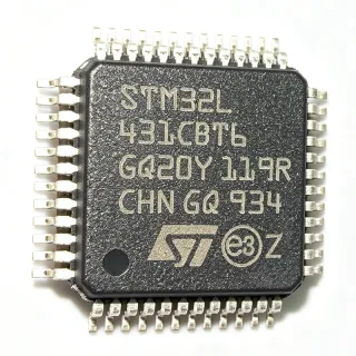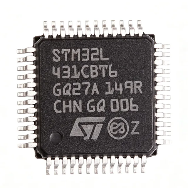
STM32L431CBT6 - ARM Cortex-M4 80MHz MCU | STMicroelectronics
MPN: STM32L431CBT6 ✓ Active| Qty | Unit Price | Extended |
|---|---|---|
| 1 | $4.0768 | $4.08 |
STM32L431CBT6 Overview
What is a microcontroller? A microcontroller (MCU) is a compact integrated circuit designed to govern a specific operation in an embedded system. It contains a processor core, memory (flash and SRAM), and programmable input/output peripherals on a single chip. Microcontrollers are the brains of countless electronic devices, from automotive engine control units to IoT sensors and wearable health monitors. The STM32L431CBT6 belongs to the STM32L4 family, which is optimized for low power consumption without compromising performance, making it ideal for battery-powered and energy-harvesting applications.
Key features of the STM32L431CBT6 include an ARM Cortex-M4 core with FPU, 80 MHz maximum clock speed, 128 KB flash, 64 KB SRAM, and a comprehensive set of peripherals such as multiple USARTs, SPIs, I2Cs, ADCs, DACs, timers, and a real-time clock. It also integrates a true random number generator (RNG), a CRC calculation unit, and a memory protection unit (MPU). The device supports a wide supply voltage range from 1.71V to 3.6V and operates over a temperature range of -40°C to +85°C.
Technically, the STM32L431CBT6 leverages the ARM Cortex-M4 architecture with DSP instructions and a single-precision FPU, enabling efficient digital signal processing. The STM32L4 series is built on a low-power process technology, achieving ultra-low power consumption in run, sleep, and standby modes. The device includes multiple low-power modes, such as Sleep, Low-power run, Low-power sleep, Stop 0/1/2, and Standby, allowing designers to optimize energy usage based on application requirements.
Typical applications include industrial sensors, IoT devices, smart home controllers, portable medical devices, and battery management systems. The combination of low power, high performance, and rich peripherals makes it suitable for applications requiring both computational capability and energy efficiency.
When designing with this MCU, pay attention to power supply decoupling and proper grounding. Use a 100nF capacitor close to each VDD pin and a 4.7uF bulk capacitor. For low-power modes, configure the clock system and peripheral clocks appropriately to minimize current consumption. The STM32L431CBT6 supports in-circuit programming and debugging via SWD, facilitating firmware development.
This page synthesizes distributor pricing, drop-in alternatives, and practical design notes not found in the ST datasheet, providing a comprehensive resource for engineers evaluating the STM32L431CBT6.
Drop-in alternatives for STM32L431CBT6 — same package, pin-to-pin compatible. Different-package parts requiring PCB rework are excluded.
Quick Comparison Tool — Select alternative parts for side-by-side comparison:
STM32L431CBT6TR
📋 Reference alternative (not in catalog)
STM32L431CCT6
📋 Reference alternative (not in catalog)
STM32L431RBT6
📋 Reference alternative (not in catalog)
STM32L431CBT6 Maximum Ratings & Electrical Characteristics
| Core | ARM Cortex-M4 with FPU |
| Maximum Clock Frequency | 80 MHz |
| Flash Memory | 128 KB |
| SRAM | 64 KB |
| Supply Voltage Range | 1.71 V to 3.6 V |
| Operating Temperature Range | -40°C to +85°C |
| Package | LQFP-48 (7x7 mm) |
| Mounting Type | Surface Mount |
| Number of I/O Pins | 38 |
| ADC Resolution | 12-bit |
| Number of ADC Channels | 16 |
| DAC Resolution | 12-bit |
| Number of DAC Channels | 2 |
| USART Interfaces | 3 |
| SPI Interfaces | 3 |
| I2C Interfaces | 3 |
| Timers | 8 (16-bit and 32-bit) |
| Real-Time Clock | Yes |
| Random Number Generator | Yes |
| CRC Calculation Unit | Yes |
| Memory Protection Unit | Yes |
| Low-Power Modes | Sleep, Low-power run, Low-power sleep, Stop 0/1/2, Standby |
| RoHS Status | Compliant |
STM32L431CBT6 Pin Configuration
| Pin 1 | VBAT — Battery backup supply for RTC and backup registers |
| Pin 2 | PC13 — GPIO or RTC tamper pin |
| Pin 3 | PC14 — GPIO or OSC32_IN |
| Pin 4 | PC15 — GPIO or OSC32_OUT |
| Pin 5 | PF0 — GPIO or OSC_IN |
| Pin 6 | PF1 — GPIO or OSC_OUT |
| Pin 7 | NRST — Reset (active low) |
| Pin 8 | VDD — Digital power supply |
| Pin 9 | VSS — Ground |
| Pin 10 | PA0 — GPIO/ADC_IN0/WKUP1 |
| Pin 11 | PA1 — GPIO/ADC_IN1 |
| Pin 12 | PA2 — GPIO/ADC_IN2/USART2_TX |
| Pin 13 | PA3 — GPIO/ADC_IN3/USART2_RX |
| Pin 14 | PA4 — GPIO/ADC_IN4/DAC_OUT1 |
| Pin 15 | PA5 — GPIO/ADC_IN5/DAC_OUT2 |
| Pin 16 | PA6 — GPIO/ADC_IN6/SPI1_MISO |
| Pin 17 | PA7 — GPIO/ADC_IN7/SPI1_MOSI |
| Pin 18 | PB0 — GPIO/ADC_IN8 |
| Pin 19 | PB1 — GPIO/ADC_IN9 |
| Pin 20 | PB2 — GPIO/BOOT1 |
| Pin 21 | PB10 — GPIO/I2C2_SCL/USART3_TX |
| Pin 22 | PB11 — GPIO/I2C2_SDA/USART3_RX |
| Pin 23 | PB12 — GPIO/SPI2_NSS |
| Pin 24 | PB13 — GPIO/SPI2_SCK |
| Pin 25 | PB14 — GPIO/SPI2_MISO |
| Pin 26 | PB15 — GPIO/SPI2_MOSI |
| Pin 27 | PA8 — GPIO/MCO1 |
| Pin 28 | PA9 — GPIO/USART1_TX |
| Pin 29 | PA10 — GPIO/USART1_RX |
| Pin 30 | PA11 — GPIO/USART1_CTS/USB_DM |
| Pin 31 | PA12 — GPIO/USART1_RTS/USB_DP |
| Pin 32 | PA13 — GPIO/SWDIO |
| Pin 33 | PA14 — GPIO/SWCLK |
| Pin 34 | PA15 — GPIO/JTDI |
| Pin 35 | PB3 — GPIO/JTDO/TRACESWO |
| Pin 36 | PB4 — GPIO/NJTRST |
| Pin 37 | PB5 — GPIO/I2C1_SMBA |
| Pin 38 | PB6 — GPIO/I2C1_SCL |
| Pin 39 | PB7 — GPIO/I2C1_SDA |
| Pin 40 | BOOT0 — Boot mode selection |
| Pin 41 | PB8 — GPIO/I2C1_SCL/CAN_RX |
| Pin 42 | PB9 — GPIO/I2C1_SDA/CAN_TX |
| Pin 43 | VDD — Digital power supply |
| Pin 44 | VSS — Ground |
| Pin 45 | PC14 — GPIO/OSC32_IN |
| Pin 46 | PC15 — GPIO/OSC32_OUT |
| Pin 47 | PC13 — GPIO/RTC_TAMP1 |
| Pin 48 | VBAT — Battery backup supply |
Typical Applications
STM32L431CBT6 is suitable for 6 applications: Industrial Sensors, IoT Devices, Portable Medical Devices, Smart Home Controllers, Battery Management Systems, Test and Measurement Equipment.
Industrial Sensors
The STM32L431CBT6 is ideal for industrial sensors due to its ultra-low-power consumption and high-performance ARM Cortex-M4 core. It can process sensor data in real-time while maintaining low energy usage, making it suitable for battery-powered or energy-harvesting sensor nodes. The MCU's multiple ADC channels (up to 16) allow direct interfacing with analog sensors, while its USART, SPI, and I2C interfaces enable communication with digital sensors and industrial networks. The wide operating temperature range (-40°C to +85°C) ensures reliable operation in harsh industrial environments. Additionally, the STM32L431CBT6's low-power modes, such as Stop 2 with 1.2 µA current consumption, extend battery life in remote monitoring applications. The FPU accelerates floating-point calculations for sensor calibration and signal conditioning, improving measurement accuracy. Designers can use the STM32CubeMX tool to configure peripherals and generate initialization code, reducing development time. The MCU's robust security features, including a true random number generator and memory protection unit, enhance system reliability and data integrity.
Recommended
IoT Devices
The STM32L431CBT6 is an excellent choice for IoT devices, offering a balance of performance and power efficiency. Its 80 MHz Cortex-M4 core with FPU can handle complex protocols like MQTT and TLS, while its ultra-low-power modes enable long battery life for wireless sensors and smart home devices. The MCU supports various communication interfaces, including USART, SPI, and I2C, allowing seamless integration with Wi-Fi, Bluetooth, and LoRa modules. The 128 KB flash and 64 KB SRAM provide ample space for application code and data buffering. The STM32L431CBT6's multiple timers and ADC channels facilitate sensor reading and actuator control. In IoT applications, the MCU can wake from Stop mode periodically to read sensors and transmit data, consuming only microamps in sleep. The device's security features, such as a true random number generator and CRC unit, support secure communication and data integrity. With STM32CubeMX and STM32CubeIDE, developers can quickly prototype and deploy IoT solutions. The wide supply voltage range (1.71V to 3.6V) allows direct battery operation, simplifying power supply design.
Recommended
Portable Medical Devices
The STM32L431CBT6 is well-suited for portable medical devices such as glucose monitors, pulse oximeters, and wearable health trackers. Its ultra-low-power consumption extends battery life, which is critical for continuous health monitoring. The MCU's high-performance Cortex-M4 core with FPU enables real-time signal processing for biosignals like ECG and PPG. The integrated 12-bit ADC with up to 16 channels can acquire analog signals from sensors, while the DAC can generate analog outputs for stimulation or calibration. The device's low-power modes allow the MCU to operate in sleep mode between measurements, reducing average current consumption to microamps. The STM32L431CBT6's rich peripheral set includes timers for precise timing of measurements and communication interfaces for data transfer to a smartphone or cloud. The wide operating temperature range and supply voltage range make it suitable for body-worn devices. Additionally, the MCU's security features, including a memory protection unit, help protect patient data. With STM32CubeMX, developers can configure the MCU for specific medical applications, ensuring compliance with medical device standards.
Recommended
Smart Home Controllers
The STM32L431CBT6 is an ideal microcontroller for smart home controllers, providing the processing power and connectivity needed to manage lighting, HVAC, security, and appliances. Its 80 MHz Cortex-M4 core can handle complex automation algorithms and user interfaces, while its low-power modes ensure energy efficiency when the system is idle. The MCU's multiple USART, SPI, and I2C interfaces allow connection to various sensors, actuators, and communication modules (e.g., Zigbee, Z-Wave, Wi-Fi). The integrated ADC and DAC enable analog sensor reading and control of analog actuators. The STM32L431CBT6's real-time clock (RTC) supports scheduling and time-based automation. With 128 KB flash and 64 KB SRAM, it can store configuration data and run a real-time operating system (RTOS) for multitasking. The device's wide supply voltage range (1.71V to 3.6V) allows direct connection to battery or USB power. The STM32L431CBT6 also supports secure boot and firmware updates, enhancing system security. Using STM32CubeMX, developers can quickly configure the MCU for smart home applications, reducing time-to-market.
Recommended
Battery Management Systems
The STM32L431CBT6 is well-suited for battery management systems (BMS) in electric vehicles, portable electronics, and energy storage systems. Its high-performance Cortex-M4 core with FPU can execute complex battery state-of-charge (SoC) and state-of-health (SoH) algorithms. The MCU's multiple ADC channels can monitor cell voltages, currents, and temperatures with high precision. The integrated DAC can be used for calibration or to control analog front-ends. The STM32L431CBT6's communication interfaces (USART, SPI, I2C) enable connection to battery monitoring ICs, such as the BQ76940, and to a host controller. The device's low-power modes are beneficial for BMS in standby, reducing quiescent current. The wide operating temperature range (-40°C to +85°C) ensures reliable operation in automotive and industrial environments. The MCU's security features, including a memory protection unit and true random number generator, enhance system safety and data integrity. With STM32CubeMX, developers can configure the MCU for specific BMS topologies, and the FPU accelerates floating-point calculations for accurate SoC estimation. The STM32L431CBT6's 128 KB flash provides ample space for BMS firmware and calibration data.
Recommended
Test and Measurement Equipment
The STM32L431CBT6 is an excellent choice for test and measurement equipment such as data loggers, multimeters, and oscilloscopes. Its high-speed 80 MHz Cortex-M4 core with FPU enables fast data acquisition and processing. The MCU's multiple 12-bit ADC channels (up to 16) can sample analog signals with high resolution, while the DAC can generate analog test signals. The device's timers provide precise timebase for measurements, and its communication interfaces (USART, SPI, I2C) allow data transfer to a PC or display. The STM32L431CBT6's low-power modes are beneficial for portable instruments, extending battery life. The wide operating temperature range ensures reliable operation in various environments. The MCU's large flash and SRAM allow storing measurement data and running complex algorithms. The FPU accelerates mathematical computations for signal analysis, such as FFT. With STM32CubeMX, developers can configure the MCU for specific measurement applications, and the STM32L431CBT6's rich peripheral set supports various sensor interfaces. The device's security features, including a true random number generator, can be used for calibration and authentication.
Recommended
Recommended Products Summary
Engineering reference data for STM32L431CBT6 — comparison, design guidance, and compliance information.
Selection Guide
Comparison with Alternatives
| Parameter | This Product | STM32L431CBT6TR | STM32L431CCT6 | STM32L431RBT6 |
|---|---|---|---|---|
| Package | LQFP-48 (7x7 mm) | LQFP-48 (7x7 mm) - same | LQFP-48 (7x7 mm) - same | LQFP-64 (10x10 mm) - different |
| Flash Memory | 128 KB | 128 KB | 256 KB | 128 KB |
| SRAM | 64 KB | 64 KB | 64 KB | 64 KB |
| Maximum Clock Frequency | 80 MHz | 80 MHz | 80 MHz | 80 MHz |
| Number of I/O Pins | 38 | 38 | 38 | 51 |
| ADC Channels | 16 | 16 | 16 | 16 |
| DAC Channels | 2 | 2 | 2 | 2 |
| Supply Voltage Range | 1.71V to 3.6V | 1.71V to 3.6V | 1.71V to 3.6V | 1.71V to 3.6V |
| Operating Temperature Range | -40°C to +85°C | -40°C to +85°C | -40°C to +85°C | -40°C to +85°C |
Key Differentiators
- Ultra-low-power consumption with 1.2 µA in Stop 2 mode (vs STM32L431CCT6)
- 128 KB flash and 64 KB SRAM in a compact LQFP-48 package (vs STM32L431RBT6)
- Pin-to-pin compatible with STM32L431CCT6 for easy upgrade path (vs STM32L431CCT6)
Design Notes
Decouple each VDD pin with a 100nF ceramic capacitor placed as close as possible to the pin, and add a 4.7uF bulk capacitor. For the VDDA pin, use a 1uF capacitor and a ferrite bead to isolate analog noise. Ensure the VBAT pin is connected to a backup battery or tied to VDD through a diode to maintain RTC operation during power loss.
For the LQFP-48 package, ensure proper solder paste stencil design to avoid bridging between pins. Use a 0.5mm pitch land pattern with appropriate solder mask expansion. Provide a solid ground plane under the MCU to reduce EMI and improve thermal performance. Route high-speed signals away from the crystal oscillator pins to minimize noise coupling.
When using low-power modes, ensure all unused GPIOs are configured to analog mode to avoid floating inputs and excessive leakage. Also, disable the MCO output if not needed, as it can consume significant current. For the RTC, use a 32.768kHz crystal with proper load capacitors (typically 6-12pF) to ensure accurate timekeeping.
Compliance Information
RoHS compliant per STMicroelectronics product page. Not AEC-Q100 qualified - this is a standard grade device.