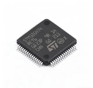
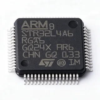
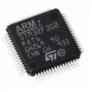
STM8AF52AATCY - 8-bit Automotive MCU, 128KB Flash, LQFP64 | STMicroelectronics
MPN: STM8AF52AATCY ✓ Active| Qty | Unit Price | Extended |
|---|---|---|
| 1 | $4.32 | $4.32 |
| 10 | $3.89 | $38.90 |
| 100 | $3.46 | $346.00 |
| 500 | $3.11 | $1,555.00 |
| 1,000 | $2.77 | $2,770.00 |
STM8AF52AATCY Overview
An 8-bit microcontroller (MCU) is a single-chip computer with an 8-bit data bus, typically used for embedded control applications where cost, power, and simplicity are prioritized over raw processing power. The STM8A core is an enhanced 8-bit architecture with a three-stage pipeline, allowing most instructions to execute in a single clock cycle. This places the STM8AF52AATCY in the hierarchy: 8-bit MCU -> microcontroller -> embedded processor -> semiconductor, and it competes with other 8-bit automotive MCUs like the Renesas RL78 and Microchip PIC18 families.
Key features include a wide operating voltage range of 3.0V to 5.5V, an operating temperature range of -40°C to +150°C (AEC-Q100 Grade 0), and a rich set of communication interfaces. The integrated CAN 2.0B controller and LIN support make it ideal for automotive networking. The 10-bit ADC with up to 16 channels enables precise sensor monitoring, while the advanced timer peripherals support PWM generation for motor control. The device also includes a true EEPROM with up to 300k write/erase cycles, eliminating the need for external EEPROM in many designs.
Architecturally, the STM8AF52AATCY uses a Harvard architecture with separate program and data memory buses, allowing simultaneous instruction fetch and data access. The core includes a 24-bit program counter, 16-bit stack pointer, and a rich instruction set optimized for control applications. The Flash memory is organized into 128 KB with read-while-write capability, enabling firmware updates without halting the system. The device also features a flexible clock system with internal and external oscillators, including a low-power RC oscillator for standby modes.
Typical applications include automotive body control modules (BCM), power window and seat control, HVAC systems, and motor control for pumps and fans. The CAN interface allows seamless integration into vehicle networks, while the LIN interface supports low-cost sub-networks. The wide temperature range and AEC-Q100 qualification ensure reliable operation in harsh automotive environments.
When designing with this MCU, pay attention to the power supply decoupling: place a 100nF capacitor close to each VDD pin and a 4.7uF bulk capacitor on the main supply. The STM8A core is 5V tolerant, but ensure the ADC reference voltage is stable for accurate conversions. Also, configure the option bytes correctly for the desired clock source and watchdog settings before production.
Drop-in alternatives for STM8AF52AATCY — same package, pin-to-pin compatible. Different-package parts requiring PCB rework are excluded.
Quick Comparison Tool — Select alternative parts for side-by-side comparison:
STM8AF52A8TCY
✅ Drop-In ⚠️ Specs Unverified📋 Reference alternative (not in catalog)
STM8AF51AATCY
✅ Drop-In ⚠️ Specs Unverified📋 Reference alternative (not in catalog)
STM8AF53AATCY
✅ Drop-In ⚠️ Specs Unverified📋 Reference alternative (not in catalog)
STM8AF52A9TCY
✅ Drop-In ⚠️ Specs Unverified📋 Reference alternative (not in catalog)
STM8AF52AATCX
✅ Drop-In ⚠️ Specs Unverified📋 Reference alternative (not in catalog)
STM8AF52AATCY Maximum Ratings & Electrical Characteristics
| Core | STM8A 8-bit |
| Maximum Clock Frequency | 24 MHz |
| Flash Memory | 128 KB |
| RAM | 6 KB |
| EEPROM | 2 KB |
| Operating Voltage | 3.0 V to 5.5 V |
| Operating Temperature | -40C to +150C |
| Package | LQFP-64 (10x10 mm) |
| Mounting Type | Surface Mount |
| Number of I/O Pins | 52 |
| ADC Resolution | 10-bit |
| ADC Channels | 16 |
| CAN Interface | 1x CAN 2.0B |
| LIN/UART | 2x LIN/UART |
| SPI | 1x SPI |
| I2C | 1x I2C |
| Timers | 2x 16-bit advanced, 2x 16-bit general purpose, 1x 8-bit basic |
| AEC-Q100 | Grade 0 |
| RoHS | Compliant |
STM8AF52AATCY Pin Configuration
| Pin 1 | PE2 — Port E2, general purpose I/O |
| Pin 2 | PE3 — Port E3, general purpose I/O |
| Pin 3 | PE4 — Port E4, general purpose I/O |
| Pin 4 | PE5 — Port E5, general purpose I/O |
| Pin 5 | VSS — Ground |
| Pin 6 | VDD — Power supply |
| Pin 7 | PE6 — Port E6, general purpose I/O |
| Pin 8 | PE7 — Port E7, general purpose I/O |
| Pin 9 | PD0 — Port D0, general purpose I/O |
| Pin 10 | PD1 — Port D1, general purpose I/O |
| Pin 11 | PD2 — Port D2, general purpose I/O |
| Pin 12 | PD3 — Port D3, general purpose I/O |
| Pin 13 | PD4 — Port D4, general purpose I/O |
| Pin 14 | PD5 — Port D5, general purpose I/O |
| Pin 15 | PD6 — Port D6, general purpose I/O |
| Pin 16 | PD7 — Port D7, general purpose I/O |
| Pin 17 | VSS — Ground |
| Pin 18 | VDD — Power supply |
| Pin 19 | PC0 — Port C0, general purpose I/O |
| Pin 20 | PC1 — Port C1, general purpose I/O |
| Pin 21 | PC2 — Port C2, general purpose I/O |
| Pin 22 | PC3 — Port C3, general purpose I/O |
| Pin 23 | PC4 — Port C4, general purpose I/O |
| Pin 24 | PC5 — Port C5, general purpose I/O |
| Pin 25 | PC6 — Port C6, general purpose I/O |
| Pin 26 | PC7 — Port C7, general purpose I/O |
| Pin 27 | PB0 — Port B0, general purpose I/O |
| Pin 28 | PB1 — Port B1, general purpose I/O |
| Pin 29 | PB2 — Port B2, general purpose I/O |
| Pin 30 | PB3 — Port B3, general purpose I/O |
| Pin 31 | PB4 — Port B4, general purpose I/O |
| Pin 32 | PB5 — Port B5, general purpose I/O |
| Pin 33 | PB6 — Port B6, general purpose I/O |
| Pin 34 | PB7 — Port B7, general purpose I/O |
| Pin 35 | VSS — Ground |
| Pin 36 | VDD — Power supply |
| Pin 37 | PA0 — Port A0, general purpose I/O |
| Pin 38 | PA1 — Port A1, general purpose I/O |
| Pin 39 | PA2 — Port A2, general purpose I/O |
| Pin 40 | PA3 — Port A3, general purpose I/O |
| Pin 41 | PA4 — Port A4, general purpose I/O |
| Pin 42 | PA5 — Port A5, general purpose I/O |
| Pin 43 | PA6 — Port A6, general purpose I/O |
| Pin 44 | PA7 — Port A7, general purpose I/O |
| Pin 45 | VREF+ — ADC reference voltage |
| Pin 46 | VSS — Ground |
| Pin 47 | VDD — Power supply |
| Pin 48 | PE0 — Port E0, general purpose I/O |
| Pin 49 | PE1 — Port E1, general purpose I/O |
| Pin 50 | NRST — Reset (active low) |
| Pin 51 | PF0 — Port F0, general purpose I/O |
| Pin 52 | PF1 — Port F1, general purpose I/O |
| Pin 53 | PF2 — Port F2, general purpose I/O |
| Pin 54 | PF3 — Port F3, general purpose I/O |
| Pin 55 | PF4 — Port F4, general purpose I/O |
| Pin 56 | PF5 — Port F5, general purpose I/O |
| Pin 57 | PF6 — Port F6, general purpose I/O |
| Pin 58 | PF7 — Port F7, general purpose I/O |
| Pin 59 | VSS — Ground |
| Pin 60 | VDD — Power supply |
| Pin 61 | OSCIN — External oscillator input |
| Pin 62 | OSCOUT — External oscillator output |
| Pin 63 | PG0 — Port G0, general purpose I/O |
| Pin 64 | PG1 — Port G1, general purpose I/O |
Typical Applications
STM8AF52AATCY is suitable for 6 applications: Automotive Body Control Module, Motor Control for Pumps and Fans, Automotive Lighting Control, HVAC Control System, Electric Power Steering (EPS), Industrial Automation and Control.
Automotive Body Control Module
The STM8AF52AATCY is ideal for body control modules (BCM) that manage lighting, windows, locks, and wipers. Its CAN interface allows communication with the vehicle network, while the 128 KB Flash provides ample space for complex control algorithms and diagnostics. The wide operating voltage (3.0V-5.5V) and AEC-Q100 Grade 0 temperature range (-40°C to +150°C) ensure reliable operation in harsh automotive environments. The 10-bit ADC monitors switch inputs and sensor signals, and the advanced timers generate PWM for dimming and motor control. The LIN interface supports low-cost sub-networks for door modules and seat control. With 52 I/O pins, it can handle multiple inputs and outputs, making it a versatile choice for BCM designs.
Recommended
Motor Control for Pumps and Fans
The STM8AF52AATCY excels in motor control applications such as electric water pumps, cooling fans, and HVAC blowers. Its two advanced 16-bit timers generate complementary PWM signals with dead-time insertion, essential for driving H-bridges or 3-phase inverters. The 10-bit ADC with up to 16 channels samples motor phase currents and rotor position sensors, enabling sensorless or sensored field-oriented control (FOC). The CAN interface allows coordination with the engine control unit (ECU) for demand-based operation. The 24 MHz core provides sufficient processing power for real-time control loops, while the 128 KB Flash stores complex control algorithms and calibration data. The wide temperature range and AEC-Q100 qualification ensure reliable operation under hood, where temperatures can exceed 125°C.
Recommended
Automotive Lighting Control
The STM8AF52AATCY is well-suited for automotive lighting control, including headlamps, tail lamps, and interior lighting. Its advanced timers can generate PWM signals for dimming and intensity control, while the 10-bit ADC monitors ambient light sensors and switch inputs. The CAN interface allows communication with the body control module for adaptive lighting functions. The 128 KB Flash stores lighting patterns and diagnostic routines, and the 2 KB EEPROM retains calibration data and fault codes. The wide operating voltage range (3.0V-5.5V) accommodates battery voltage variations, and the AEC-Q100 Grade 0 temperature range ensures operation in extreme conditions. The 52 I/O pins provide ample connectivity for multiple LED drivers and switches.
Recommended
HVAC Control System
The STM8AF52AATCY is ideal for automotive HVAC control systems, managing temperature, airflow, and compressor operation. Its multiple communication interfaces (CAN, LIN, UART) allow integration with the vehicle network and sensor modules. The 10-bit ADC reads temperature sensors and potentiometers for user controls, while the advanced timers generate PWM for blower motor speed control and actuator positioning. The 128 KB Flash stores complex control algorithms for automatic climate control, and the 2 KB EEPROM retains user preferences and diagnostic data. The wide operating temperature range (-40°C to +150°C) ensures reliable operation in both cold and hot climates, and the AEC-Q100 qualification guarantees long-term reliability.
Recommended
Electric Power Steering (EPS)
The STM8AF52AATCY can be used in electric power steering systems, where it processes torque sensor signals and controls the assist motor. The 10-bit ADC with high resolution samples torque and angle sensors, while the advanced timers generate PWM for the motor drive. The CAN interface communicates with the vehicle stability control system for coordinated steering assistance. The 24 MHz core provides fast response times for safety-critical control loops, and the 128 KB Flash stores complex control algorithms and safety diagnostics. The AEC-Q100 Grade 0 qualification ensures operation in the harsh under-hood environment, and the wide voltage range (3.0V-5.5V) accommodates battery voltage fluctuations. The 52 I/O pins allow connection to multiple sensors and actuators.
Recommended
Industrial Automation and Control
Beyond automotive, the STM8AF52AATCY is suitable for industrial automation and control applications such as PLCs, motor drives, and sensor interfaces. Its robust communication interfaces (CAN, SPI, I2C, UART) enable connection to industrial networks and peripherals. The 10-bit ADC monitors analog sensors, and the advanced timers generate precise PWM for motor control and actuator positioning. The wide operating voltage range (3.0V-5.5V) and industrial temperature range (-40°C to +150°C) make it suitable for harsh industrial environments. The 128 KB Flash provides ample space for control algorithms and data logging, and the 2 KB EEPROM stores configuration parameters. The 52 I/O pins offer flexibility for various input/output configurations.
Recommended
Recommended Products Summary
Engineering reference data for STM8AF52AATCY — comparison, design guidance, and compliance information.
Selection Guide
Comparison with Alternatives
| Parameter | This Product | STM8AF52A8TCY | STM8AF51AATCY | STM8AF53AATCY |
|---|---|---|---|---|
| Package | LQFP-64 | LQFP-64 | LQFP-64 | LQFP-64 |
| Brand | STMicroelectronics | STMicroelectronics | STMicroelectronics | STMicroelectronics |
| Flash Memory | 128 KB | 128 KB | 64 KB | 256 KB |
| RAM | 6 KB | 6 KB | 4 KB | 8 KB |
| EEPROM | 2 KB | 2 KB | 2 KB | 2 KB |
| Maximum Clock Frequency | 24 MHz | 24 MHz | 24 MHz | 24 MHz |
| Operating Temperature | -40C to +150C | -40C to +150C | -40C to +150C | -40C to +150C |
| AEC-Q100 Grade | Grade 0 | Grade 0 | Grade 0 | Grade 0 |
| CAN Interface | 1x CAN 2.0B | 1x CAN 2.0B | 1x CAN 2.0B | 1x CAN 2.0B |
| Number of I/O Pins | 52 | 52 | 52 | 52 |
Key Differentiators
- AEC-Q100 Grade 0 qualification (vs STM8AF52A9TCY)
- 128 KB Flash memory (vs STM8AF51AATCY)
- Cost-effective 8-bit architecture (vs STM8AF53AATCY)
Design Notes
The STM8AF52AATCY operates from 3.0V to 5.5V. For automotive applications, use a low-dropout regulator (LDO) to step down the battery voltage (12V) to 5V. Place a 100nF ceramic capacitor close to each VDD pin and a 4.7uF bulk capacitor on the main supply. Ensure the VREF+ pin is connected to a stable reference voltage for accurate ADC conversions, typically the same as VDD with a 100nF decoupling capacitor.
For the LQFP-64 package, ensure proper soldering with a stencil thickness of 0.125mm. Place decoupling capacitors as close as possible to the power pins to minimize inductance. For the crystal oscillator (if used), keep traces short and shield them with ground planes to reduce noise. Follow STMicroelectronics' layout guidelines in the datasheet for optimal EMC performance.
A common pitfall is forgetting to configure the option bytes for the clock source and watchdog. The STM8AF52AATCY defaults to an internal RC oscillator, but for precise timing, use an external crystal. Also, ensure the NRST pin is properly pulled up with a 100nF capacitor to ground for reliable reset. Do not leave unused I/O pins floating; configure them as inputs with pull-ups or outputs to avoid excessive current consumption.
Compliance Information
AEC-Q100 Grade 0 qualified. RoHS compliant per STMicroelectronics product page. Halogen-free status not explicitly stated in provided data.