STM32F413RHT6 - 1.5MB Flash ARM Cortex-M4F MCU | STMicroelectronics
MPN: STM32F413RHT6 ✓ Active| Qty | Unit Price | Extended |
|---|---|---|
| 1 | $8.4101 | $8.41 |
STM32F413RHT6 Overview
What is an ARM Cortex-M4F microcontroller? It is a 32-bit processor core designed for embedded systems, combining the efficient ARM Cortex-M4 core with a hardware floating-point unit (FPU) that accelerates single-precision floating-point arithmetic. This makes it ideal for digital signal processing (DSP) and control applications. In the system hierarchy, a microcontroller (MCU) integrates a processor core, memory, and peripherals on a single chip, serving as the 'brain' of embedded systems. The STM32F413 series sits in the mid-to-high performance range of ST's STM32 portfolio, offering a balance of performance, memory, and peripheral integration.
Key features include a rich set of communication interfaces: 6x SPI, 3x I2C, 4x USART, 2x UART, 2x CAN, 1x SDMMC, 1x USB OTG FS, and 1x SAI. It also integrates a 12-bit ADC with up to 16 channels, a 12-bit DAC with 2 channels, advanced timers, and a true random number generator (TRNG). The device supports a wide range of power-saving modes, including Sleep, Stop, and Standby, with typical power consumption as low as 1.8 uA in Standby mode. The operating temperature range is -40C to +85C, making it suitable for industrial environments.
Technically, the STM32F413RHT6 is built on a 90nm process technology, offering a good balance of performance and power efficiency. The Cortex-M4F core with FPU and DSP instructions enables efficient execution of complex algorithms, such as FFTs and control loops. The memory architecture includes a 1.5MB Flash with read-while-write support and 320KB SRAM, allowing for large data buffers and multitasking. The device also features a memory protection unit (MPU) for enhanced security and reliability.
Typical applications include industrial control systems, motor control, medical devices, consumer electronics, and IoT gateways. The rich peripheral set and high memory capacity make it suitable for applications requiring connectivity, such as smart home hubs and industrial automation. The USB OTG FS interface enables direct connection to PCs or mobile devices for data transfer and firmware updates.
When designing with this MCU, ensure proper decoupling of the power supply pins with 100nF capacitors placed close to each VDD pin. The VDDA pin should be connected to a clean analog supply, and the VREF+ pin should be decoupled with a 1uF capacitor. For reliable operation, the NRST pin should have a 100nF capacitor to ground. The device supports SWD and JTAG debugging, with SWD recommended for production to save pins.
Drop-in alternatives for STM32F413RHT6 — same package, pin-to-pin compatible. Different-package parts requiring PCB rework are excluded.
Variants in this series
Same-series models that are drop-in compatible with STM32F413RHT6 (same form factor and footprint) — differing in ADC Resolution, Communication Interfaces, Flash Memory, Package, SRAM.
Quick Comparison Tool — Select alternative parts for side-by-side comparison:
STM32F413RGT6
✅ Drop-In ⚠️ Specs Unverified📋 Reference alternative (not in catalog)
STM32F423RHT6
✅ Drop-In ⚠️ Specs Unverified📋 Reference alternative (not in catalog)
STM32F413RHT6TR
✅ Drop-In ⚠️ Specs Unverified📋 Reference alternative (not in catalog)
STM32F411RET6
✅ Drop-In ⚠️ Specs Unverified✓ In Stock
$4.02 / Unit
View Datasheet →STM32F446RET6
⚡ Same Package ⚠️ Specs Unverified✓ In Stock
$8.94 / Unit
View Datasheet →LPC4327FBD208
✅ Drop-In ⚠️ Specs Unverified📋 Reference alternative (not in catalog)
R5F565NEDFP
✅ Drop-In ⚠️ Specs Unverified📋 Reference alternative (not in catalog)
STM32F413RHT6 Maximum Ratings & Electrical Characteristics
| Core | ARM Cortex-M4F with FPU |
| Maximum Clock Frequency | 100 MHz |
| Flash Memory | 1.5 MB |
| SRAM | 320 KB |
| Supply Voltage Range | 1.7 V to 3.6 V |
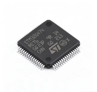
| Package | LQFP-64 (10x10 mm) |
| Operating Temperature Range | -40C to +85C |
| Number of I/O Pins | 50 |
| ADC Resolution | 12-bit |
| Number of ADC Channels | 16 |
| DAC Resolution | 12-bit |
| Number of DAC Channels | 2 |
| Communication Interfaces | 6x SPI, 3x I2C, 4x USART, 2x UART, 2x CAN, 1x SDMMC, 1x USB OTG FS, 1x SAI |
| Timers | Advanced-control, general-purpose, basic, and low-power timers |
| DMA Channels | 16 |
| Standby Current | 1.8 uA |
| RoHS Status | Compliant |
STM32F413RHT6 Pin Configuration
| Pin 1 | VBAT — Backup battery supply |
| Pin 2 | PC13 — GPIO or RTC tamper |
| Pin 3 | PC14 — GPIO or OSC32_IN |
| Pin 4 | PC15 — GPIO or OSC32_OUT |
| Pin 5 | PF0 — GPIO |
| Pin 6 | PF1 — GPIO |
| Pin 7 | NRST — Reset (active low) |
| Pin 8 | VSSA — Analog ground |
| Pin 9 | VDDA — Analog power supply |
| Pin 10 | PA0 — GPIO/ADC |
| Pin 11 | PA1 — GPIO/ADC |
| Pin 12 | PA2 — GPIO/USART2_TX |
| Pin 13 | PA3 — GPIO/USART2_RX |
| Pin 14 | PA4 — GPIO/SPI1_NSS |
| Pin 15 | PA5 — GPIO/SPI1_SCK |
| Pin 16 | PA6 — GPIO/SPI1_MISO |
| Pin 17 | PA7 — GPIO/SPI1_MOSI |
| Pin 18 | PC4 — GPIO/ADC |
| Pin 19 | PC5 — GPIO/ADC |
| Pin 20 | PB0 — GPIO/ADC |
| Pin 21 | PB1 — GPIO/ADC |
| Pin 22 | PB2 — GPIO |
| Pin 23 | PF7 — GPIO |
| Pin 24 | PF8 — GPIO |
| Pin 25 | PF9 — GPIO |
| Pin 26 | PF10 — GPIO |
| Pin 27 | VSS — Ground |
| Pin 28 | VDD — Power supply |
| Pin 29 | PB10 — GPIO/I2C2_SCL |
| Pin 30 | PB11 — GPIO/I2C2_SDA |
| Pin 31 | PB12 — GPIO/SPI2_NSS |
| Pin 32 | PB13 — GPIO/SPI2_SCK |
| Pin 33 | PB14 — GPIO/SPI2_MISO |
| Pin 34 | PB15 — GPIO/SPI2_MOSI |
| Pin 35 | PC6 — GPIO/TIM3_CH1 |
| Pin 36 | PC7 — GPIO/TIM3_CH2 |
| Pin 37 | PC8 — GPIO/TIM3_CH3 |
| Pin 38 | PC9 — GPIO/TIM3_CH4 |
| Pin 39 | PA8 — GPIO/USB_OTG_FS_SOF |
| Pin 40 | PA9 — GPIO/USB_OTG_FS_VBUS |
| Pin 41 | PA10 — GPIO/USB_OTG_FS_ID |
| Pin 42 | PA11 — GPIO/USB_OTG_FS_DM |
| Pin 43 | PA12 — GPIO/USB_OTG_FS_DP |
| Pin 44 | PA13 — SWDIO |
| Pin 45 | PA14 — SWCLK |
| Pin 46 | PA15 — GPIO/JTDI |
| Pin 47 | PC10 — GPIO |
| Pin 48 | PC11 — GPIO |
| Pin 49 | PC12 — GPIO |
| Pin 50 | PD2 — GPIO |
| Pin 51 | PB3 — GPIO/JTDO |
| Pin 52 | PB4 — GPIO/NJTRST |
| Pin 53 | PB5 — GPIO |
| Pin 54 | PB6 — GPIO/I2C1_SCL |
| Pin 55 | PB7 — GPIO/I2C1_SDA |
| Pin 56 | BOOT0 — Boot mode selection |
| Pin 57 | PB8 — GPIO/CAN1_RX |
| Pin 58 | PB9 — GPIO/CAN1_TX |
| Pin 59 | VSS — Ground |
| Pin 60 | VDD — Power supply |
| Pin 61 | PC0 — GPIO/ADC |
| Pin 62 | PC1 — GPIO/ADC |
| Pin 63 | PC2 — GPIO/ADC |
| Pin 64 | PC3 — GPIO/ADC |
Typical Applications
STM32F413RHT6 is suitable for 6 applications: Industrial Control Systems, Motor Control, Medical Devices, Consumer Electronics, IoT Gateways, Audio Processing.
Industrial Control Systems
The STM32F413RHT6 is ideal for industrial control systems due to its 100 MHz Cortex-M4F core, advanced timers, and multiple communication interfaces. It can handle real-time control loops, PLCs, and motor control with high precision. The device's 12-bit ADC with 16 channels enables accurate sensor reading, while the CAN interface supports robust industrial networking. Its wide operating temperature range (-40C to +85C) ensures reliability in harsh factory environments. The large Flash and SRAM allow for complex control algorithms and data logging. In a typical PLC, the MCU reads inputs, executes logic, and drives outputs with minimal latency. The FPU accelerates floating-point calculations for PID controllers, improving response time. The low-power modes help reduce energy consumption in always-on systems. Overall, the STM32F413RHT6 provides the performance and connectivity needed for modern industrial automation.
Recommended
Motor Control
The STM32F413RHT6 excels in motor control applications, such as brushless DC (BLDC) and permanent magnet synchronous motors (PMSM). Its advanced timers generate high-resolution PWM signals, while the 12-bit ADC samples phase currents and rotor position with high accuracy. The Cortex-M4F FPU accelerates field-oriented control (FOC) algorithms, enabling smooth and efficient motor operation. The device supports sensorless control using back-EMF detection, reducing system cost. With multiple communication interfaces, it can interface with encoders, drivers, and host controllers. The large SRAM allows for complex control loops and data buffering. In a typical motor drive, the MCU reads current sensors, computes the FOC algorithm, and updates PWM duty cycles in real-time. The low-latency interrupt handling ensures precise timing. The STM32F413RHT6's robust design and industrial temperature range make it suitable for pumps, fans, and robotics.
Recommended
Medical Devices
The STM32F413RHT6 is well-suited for medical devices such as patient monitors, infusion pumps, and diagnostic equipment. Its high processing power enables real-time signal processing for ECG, EEG, and blood pressure monitoring. The 12-bit ADC with 16 channels can acquire multiple physiological signals simultaneously. The device's low-power modes extend battery life in portable devices. The USB OTG FS interface allows data transfer to PCs for analysis and firmware updates. The large Flash memory stores patient data and firmware. The FPU accelerates digital filtering and feature extraction algorithms. In a patient monitor, the MCU samples ECG signals, filters noise, and displays waveforms on an LCD. The CAN interface can connect to hospital networks for centralized monitoring. The STM32F413RHT6's reliability and long-term availability make it a trusted choice for medical applications.
Recommended
Consumer Electronics
The STM32F413RHT6 is used in consumer electronics like smart home hubs, wearable devices, and audio equipment. Its rich peripheral set includes USB OTG FS for connectivity, SAI for audio interfaces, and multiple I2C/SPI for sensors and displays. The 100 MHz core handles user interfaces and communication protocols efficiently. The low-power modes are crucial for battery-powered wearables. The large Flash memory supports complex applications and over-the-air updates. In a smart home hub, the MCU manages Zigbee, Wi-Fi, and Bluetooth modules via UART/SPI, processes sensor data, and controls actuators. The FPU accelerates audio processing for voice commands. The STM32F413RHT6's small LQFP-64 package fits compact designs. Its wide operating temperature range ensures reliable operation in various environments.
Recommended
IoT Gateways
The STM32F413RHT6 is an excellent choice for IoT gateways that aggregate data from multiple sensors and devices. Its multiple communication interfaces (UART, SPI, I2C, CAN, USB) allow connection to various wireless modules (Wi-Fi, Zigbee, LoRa) and wired sensors. The 1.5 MB Flash and 320 KB SRAM provide ample space for protocol stacks and data buffering. The Cortex-M4F core with FPU handles encryption and data processing efficiently. The device supports secure boot and firmware updates via USB or UART. In a typical IoT gateway, the MCU collects data from sensors, processes it, and forwards it to the cloud via Ethernet or Wi-Fi. The low-power modes enable battery-powered gateways. The STM32F413RHT6's robust design and long-term availability make it suitable for industrial IoT deployments.
Recommended
Audio Processing
The STM32F413RHT6 is used in audio processing applications such as audio interfaces, voice recognition, and sound synthesis. Its SAI (Serial Audio Interface) supports I2S and TDM formats, enabling connection to audio codecs and DACs. The Cortex-M4F FPU accelerates audio DSP algorithms like filtering, equalization, and FFT. The large SRAM allows for audio buffering and effects processing. The USB OTG FS can stream audio to and from a host. In a typical audio interface, the MCU receives digital audio via SAI, processes it (e.g., noise reduction), and outputs via USB or SAI. The 12-bit ADC can sample analog audio for voice recognition. The STM32F413RHT6's high performance and low latency make it suitable for real-time audio applications. Its low-power modes are beneficial for portable audio devices.
Recommended
Recommended Products Summary
Engineering reference data for STM32F413RHT6 — comparison, design guidance, and compliance information.
Selection Guide
Comparison with Alternatives
| Parameter | This Product | STM32F413RGT6 | STM32F423RHT6 | STM32F411RET6 | LPC4327FBD208 |
|---|---|---|---|---|---|
| Package | LQFP-64 | LQFP-64 - same | LQFP-64 - same | LQFP-64 - same | LQFP-64 - same |
| Brand | STMicroelectronics | STMicroelectronics | STMicroelectronics | STMicroelectronics | NXP Semiconductors |
| Core | ARM Cortex-M4F @ 100 MHz | ARM Cortex-M4F @ 100 MHz | ARM Cortex-M4F @ 100 MHz | ARM Cortex-M4F @ 100 MHz | ARM Cortex-M4F @ 204 MHz |
| Flash Memory | 1.5 MB | 1 MB | 1.5 MB | 512 KB | 1 MB |
| SRAM | 320 KB | 320 KB | 320 KB | 128 KB | 136 KB |
| Communication Interfaces | 6x SPI, 3x I2C, 4x USART, 2x UART, 2x CAN, 1x SDMMC, 1x USB OTG FS, 1x SAI | Same as this product | Same as this product | 5x SPI, 3x I2C, 3x USART, 1x SDMMC, 1x USB OTG FS | 4x SPI, 3x I2C, 4x UART, 2x CAN, 1x USB OTG HS |
| ADC Channels | 16 | 16 | 16 | 16 | 8 |
| DAC Channels | 2 | 2 | 2 | 0 | 1 |
| Operating Temperature Range | -40C to +85C | -40C to +85C | -40C to +85C | -40C to +85C | -40C to +85C |
Key Differentiators
- Largest Flash memory in the STM32F4 LQFP-64 family (vs STM32F411RET6)
- Includes SAI and CAN interfaces (vs STM32F411RET6)
- Higher SRAM capacity (vs LPC4327FBD208)
Design Notes
Decouple each VDD pin with a 100nF ceramic capacitor placed as close as possible to the pin. Additionally, use a 4.7uF capacitor on the main power rail. The VDDA pin should be connected to a clean analog supply, and VREF+ should be decoupled with a 1uF capacitor. For battery-powered designs, the VBAT pin can be connected to a backup battery to maintain RTC and backup registers when main power is off.
For the LQFP-64 package, ensure proper solder paste stencil design to avoid bridging. Use a 0.5mm pitch land pattern. Place the crystal oscillator (if used) close to the OSC_IN/OSC_OUT pins with proper grounding. For USB OTG, route the DM/DP lines as a differential pair with 90-ohm impedance. Keep the SWD interface pins accessible for programming and debugging.
Do not leave the BOOT0 pin floating; connect it to ground through a 10k resistor for normal boot from Flash. Ensure the NRST pin has a 100nF capacitor to ground to prevent noise-induced resets. When using the ADC, avoid digital switching noise on the VDDA supply; use an LC filter if necessary. Also, verify that the maximum junction temperature is not exceeded; for high clock speeds and heavy loads, consider thermal relief.
Compliance Information
RoHS compliant per STMicroelectronics product page. Not AEC-Q100 qualified; for automotive, consider STM32F413RHT6Q or similar.