TMS320F280021-Q1 - Automotive C2000 MCU, 100MHz | TI
MPN: TMS320F280021-Q1 ✓ Active| Qty | Unit Price | Extended |
|---|---|---|
| 1 | $0 | $0.00 |
| 10 | $0 | $0.00 |
| 100 | $0 | $0.00 |
| 500 | $0 | $0.00 |
| 1,000 | $0 | $0.00 |
TMS320F280021-Q1 Overview
The C2000 family of microcontrollers is specifically designed for real-time control applications in power electronics, offering ultra-low latency and high performance. The TMS320F280021-Q1 belongs to the TMS320F28002x series, which supports high power density, high switching frequencies, and is optimized for use with GaN and SiC technologies.
Key features include 100 MHz CPU speed, FPU for efficient floating-point computation, and TMU for fast trigonometric calculations, essential for complex control algorithms. The automotive qualification (-Q1) ensures operation in harsh environments and compliance with AEC-Q100 requirements, making it suitable for automotive applications such as motor control, DC-DC converters, and onboard chargers.
The device is designed to deliver deterministic, low-latency performance for closed-loop control systems. The C2000 architecture includes specialized hardware for real-time control, enabling precise PWM generation, high-resolution ADC sampling, and fast interrupt handling. The TMU accelerates trigonometric operations used in space vector modulation (SVM) and other motor control algorithms, reducing CPU load.
Typical applications include industrial motor drives, automotive HEV/EV power electronics, solar inverters, server power supplies, and other power conversion systems. The TMS320F280021-Q1's combination of real-time performance, automotive-grade quality, and support for wide-bandgap semiconductors (SiC and GaN) makes it a robust choice for modern power electronics.
When designing with this MCU, ensure proper power supply decoupling and consider thermal management for high-frequency switching applications. The C28x core requires careful handling of the boot mode pins to configure the startup sequence. Additionally, the TMU and FPU enable efficient implementation of advanced control algorithms, but memory constraints (32 KB flash) should be planned accordingly.
Drop-in alternatives for TMS320F280021-Q1 — same package, pin-to-pin compatible. Different-package parts requiring PCB rework are excluded.
Variants in this series
Same-series models that are drop-in compatible with TMS320F280021-Q1 (same form factor and footprint) — differing in Automotive Qualification, Core Processor, Flash Memory Size.
Quick Comparison Tool — Select alternative parts for side-by-side comparison:
TMS320F280021
✅ Drop-In📋 Reference alternative (not in catalog)
TMS320F280023-Q1
✅ Drop-In✓ In Stock
Contact for price
View Datasheet →TMS320F280023
✅ Drop-In ⚠️ Specs Unverified📋 Reference alternative (not in catalog)
TMS320F280025-Q1
✅ Drop-In ⚠️ Specs Unverified📋 Reference alternative (not in catalog)
TMS320F280025
✅ Drop-In ⚠️ Specs Unverified📋 Reference alternative (not in catalog)
TMS320F280021-Q1 Maximum Ratings & Electrical Characteristics
| Core Processor | C28x |
| Core Size | 32-Bit |
| Speed | 100 MHz |
| Flash Memory Size | 32 KB |
| FPU | Yes |
| TMU | Yes |
| Series | TMS320F28002x |
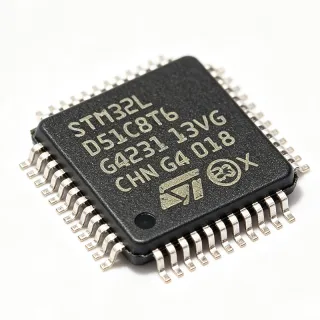
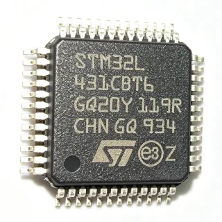
| Package | LQFP-48 (7x7 mm) |
| Mounting Type | Surface Mount |
| Automotive Qualification | AEC-Q100 Qualified |
TMS320F280021-Q1 Pin Configuration
| Pin 1 | VDD — Digital supply voltage |
| Pin 2 | VSS — Digital ground |
| Pin 3 | VDDA — Analog supply voltage |
| Pin 4 | VSSA — Analog ground |
| Pin 5 | GPIO0 — General-purpose I/O, PWM output |
| Pin 6 | GPIO1 — General-purpose I/O |
| Pin 7 | GPIO2 — General-purpose I/O |
| Pin 8 | GPIO3 — General-purpose I/O |
| Pin 9 | GPIO4 — General-purpose I/O, ADC input |
| Pin 10 | GPIO5 — General-purpose I/O |
| Pin 11 | GPIO6 — General-purpose I/O |
| Pin 12 | GPIO7 — General-purpose I/O |
| Pin 13 | GPIO8 — General-purpose I/O |
| Pin 14 | GPIO9 — General-purpose I/O |
| Pin 15 | GPIO10 — General-purpose I/O, SCI RX |
| Pin 16 | GPIO11 — General-purpose I/O, SCI TX |
| Pin 17 | GPIO12 — General-purpose I/O |
| Pin 18 | GPIO13 — General-purpose I/O |
| Pin 19 | GPIO14 — General-purpose I/O |
| Pin 20 | GPIO15 — General-purpose I/O |
| Pin 21 | GPIO16 — General-purpose I/O |
| Pin 22 | GPIO17 — General-purpose I/O |
| Pin 23 | GPIO18 — General-purpose I/O |
| Pin 24 | GPIO19 — General-purpose I/O |
| Pin 25 | GPIO20 — General-purpose I/O |
| Pin 26 | GPIO21 — General-purpose I/O |
| Pin 27 | GPIO22 — General-purpose I/O |
| Pin 28 | GPIO23 — General-purpose I/O |
| Pin 29 | GPIO24 — General-purpose I/O |
| Pin 30 | GPIO25 — General-purpose I/O |
| Pin 31 | GPIO26 — General-purpose I/O |
| Pin 32 | GPIO27 — General-purpose I/O |
| Pin 33 | GPIO28 — General-purpose I/O |
| Pin 34 | GPIO29 — General-purpose I/O |
| Pin 35 | GPIO30 — General-purpose I/O, CAN RX |
| Pin 36 | GPIO31 — General-purpose I/O, CAN TX |
| Pin 37 | GPIO32 — General-purpose I/O |
| Pin 38 | GPIO33 — General-purpose I/O |
| Pin 39 | GPIO34 — General-purpose I/O |
| Pin 40 | GPIO35 — General-purpose I/O |
| Pin 41 | GPIO36 — General-purpose I/O |
| Pin 42 | GPIO37 — General-purpose I/O |
| Pin 43 | GPIO38 — General-purpose I/O |
| Pin 44 | GPIO39 — General-purpose I/O |
| Pin 45 | GPIO40 — General-purpose I/O, ADC input |
| Pin 46 | GPIO41 — General-purpose I/O, ADC input |
| Pin 47 | GPIO42 — General-purpose I/O, ADC input |
| Pin 48 | GPIO43 — General-purpose I/O, ADC input |
Typical Applications
TMS320F280021-Q1 is suitable for 6 applications: Motor Control, Digital Power Supply, Solar Inverters, Automotive HEV/EV Power Electronics, GaN/SiC Power Conversion, Industrial Drives and PFC.
Motor Control
The TMS320F280021-Q1's 100 MHz C28x core with FPU and TMU enables precise real-time motor control algorithms such as FOC and SVM. Its automotive qualification makes it suitable for BLDC and PMSM drives in HEV/EV and industrial automation. The TMU accelerates trigonometric computations, reducing CPU load and enabling faster control loops. Design around the 32 KB flash for code that fits; use 64KB+ variants for more complex algorithms.
Recommended
Digital Power Supply
The TMS320F280021-Q1 is ideal for digital power supplies, offering high PWM resolution and synchronous sampling for PID control loops. Its 100 MHz clock allows fast compensation, while the FPU handles floating-point math for precision. Used in AC-DC and DC-DC converters, the MCU supports GaN/SiC driving with low latency. The automotive grade ensures reliability in power converters for EV chargers and server PSUs.
Recommended
Solar Inverters
For solar inverters, the TMS320F280021-Q1 handles MPPT algorithms and grid-tie control with its fast 100 MHz core and TMU. The FPU simplifies computation of sine references and PLL loops, while the high-resolution PWMs output clean switching waveforms to IGBTs or SiC MOSFETs. Its automotive-grade qualification also enables use in vehicle-integrated PV systems. The device's real-time capabilities ensure efficient energy conversion with low total harmonic distortion.
Recommended
Automotive HEV/EV Power Electronics
The TMS320F280021-Q1 is AEC-Q100 qualified, making it suitable for onboard chargers, DC-DC converters, and traction inverters in HEV/EV. Its 100 MHz core with TMU enables fast space-vector control, while the FPU handles array math for torque and flux estimation. The MCU's low latency and deterministic response ensure reliable operation in high-temperature automotive environments. It supports GaN/SiC power stages, reducing system size and losses.
Recommended
GaN/SiC Power Conversion
The TMS320F280021-Q1 is optimized for power conversion using wide-bandgap semiconductors like GaN and SiC. Its 100 MHz clock combined with the TMU provides sub-microsecond control loops for ultra-high-frequency converters, minimizing switching losses. The FPU supports complex control algorithms such as phase-shifted LLC or totem-pole PFC. Automotive qualification and support for high switching frequencies make it a preferred choice for EV chargers and industrial power supplies using GaN/SiC.
Recommended
Industrial Drives and PFC
The TMS320F280021-Q1 serves industrial variable-frequency drives and power factor correction (PFC) circuits. Its 100 MHz C28x core with FPU/TMU delivers the real-time performance needed for PWM generation and PFC control at high switching frequencies. The device supports three-phase PFC topologies and motor drive applications, with a 32 KB flash suitable for common drive firmware. Automotive-grade options available for harsh environments, and the package is compact for space-constrained controllers.
Recommended
Recommended Products Summary
Engineering reference data for TMS320F280021-Q1 — comparison, design guidance, and compliance information.
Selection Guide
Comparison with Alternatives
| Parameter | This Product | TMS320F280021 | TMS320F280023-Q1 | TMS320F280025-Q1 |
|---|---|---|---|---|
| Package | LQFP-48 | LQFP-48 | LQFP-48 | LQFP-48 |
| Brand | Texas Instruments | Texas Instruments | Texas Instruments | Texas Instruments |
| Core Frequency | 100 MHz | 100 MHz | 100 MHz | 100 MHz |
| Flash Memory | 32 KB | 32 KB | 64 KB | 128 KB |
| FPU | Yes | Yes | Yes | Yes |
| TMU | Yes | Yes | Yes | Yes |
| Automotive Grade | Yes (AEC-Q100) | No | Yes (AEC-Q100) | Yes (AEC-Q100) |
Key Differentiators
- Automotive AEC-Q100 qualification (vs TMS320F280021 (non-Q1))
- Lower flash, lower cost (vs TMS320F280023-Q1)
- High-frequency OP optimization (vs TMS320F280025-Q1)
Design Notes
Place 0.1uF and 1uF ceramic capacitors close to each VDD and VDDA pin. Use a 10uF bulk capacitor on the 3.3V supply. Ensure the analog supply (VDDA) is properly filtered with a ferrite bead to reduce noise from digital switching. Follow the datasheet's recommended decoupling scheme to maintain stable operation at 100 MHz.
The boot mode pins (GPIO72, GPIO73, GPIO74, or similar) must be configured correctly at reset to select the desired boot source (e.g., SCI, SPLASH). Incorrect boot configuration can prevent the MCU from starting. Consult the datasheet's Boot ROM chapter. Also, avoid drawing large currents from GPIO pins directly; use external drivers for high-load peripherals.
At 100 MHz operation, the TMS320F280021-Q1 dissipates power based on supply voltage and activity. Ensure adequate copper pour and thermal vias under the LQFP-48 package to keep the junction temperature within the recommended range. For automotive applications, consider ambient temperatures up to 125°C; calculate power dissipation using the datasheet's power consumption tables.
Use a four-layer PCB with a solid ground plane. Route analog and digital grounds separately and join at a single point to minimize noise. Keep the crystal oscillator circuit short and away from high-current traces. For high-frequency switching, maintain short trace lengths for PWM outputs to reduce EMI and ensure signal integrity.
Compliance Information
AEC-Q100 qualification inferred from -Q1 suffix. Other compliance values not provided in verified data.