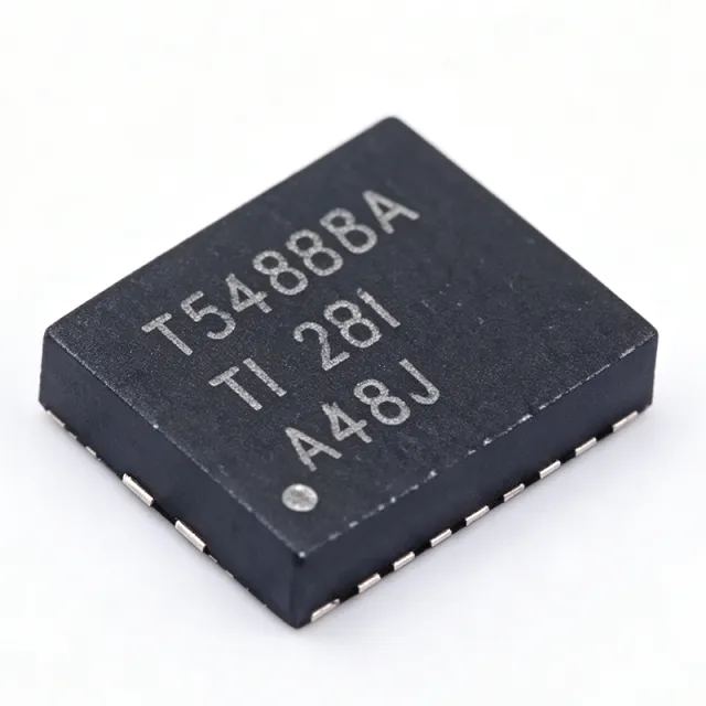
TPS548B28RWWR - 20A 16V Sync Buck Converter | TI | Datacenter
MPN: TPS548B28RWWR ✓ Active| Qty | Unit Price | Extended |
|---|---|---|
| 1 | $1 | $1.00 |
TPS548B28RWWR Overview
A synchronous buck converter is a DC-DC switching regulator that steps a higher input voltage down to a lower output voltage using two integrated switches (high-side and low-side MOSFETs) plus an external inductor. Within the power management hierarchy, the TPS548B28 belongs to the switching regulator family, positioned as a single-channel point-of-load (POL) solution between simple low-current bucks and multi-phase controllers.
Key features include a 4V to 16V input range supporting 20A continuous output without external bias, extended 2.7V operation with a 3.13V to 3.6V external bias, an output voltage range of 0.6V to 5.5V, and integrated 7.7-mΩ high-side and 2.4-mΩ low-side MOSFETs. The device offers fast load-transient response, accurate load and line regulation, Skip-mode or forced-CCM (FCCM) operation for light-load efficiency trade-offs, programmable soft start, and hiccup current limit for fault robustness.
The D-CAP3-style control architecture enables a small external component count and fast transient response with low output capacitance, well suited to space-constrained boards. The internal 3V LDO can be overridden by an external bias rail to improve efficiency at lower input voltages. Differential remote sense compensates for PCB IR drop, maintaining ±1% regulation at the load point.
Typical applications include server and storage point-of-load rails (DSP, FPGA, ASIC, and processor cores), datacenter and networking card power, and general industrial 20A-class low-voltage supplies. Reference design support is available via the TPS548B28EVM-023 evaluation module.
Design consideration: at 20A loads, minimize the SW-node copper area and optimize the input capacitor loop to control EMI; verify thermal performance since total MOSFET conduction plus switching losses concentrate in the small QFN footprint.
Drop-in alternatives for TPS548B28RWWR — same package, pin-to-pin compatible. Different-package parts requiring PCB rework are excluded.
Quick Comparison Tool — Select alternative parts for side-by-side comparison:
No drop-in alternatives available for this product.
Request AlternativesTPS548B28RWWR Maximum Ratings & Electrical Characteristics
| Topology | Synchronous Step-Down (Buck) Converter |
| Input Voltage Range (no external bias) | 4 V to 16 V |
| Input Voltage Range (with external bias) | 2.7 V to 16 V |
| External Bias Range | 3.13 V to 3.6 V |
| Maximum Output Current | 20 A |
| Output Voltage Range | 0.6 V to 5.5 V |
| Reference Voltage | 0.6 V ±1% over junction temperature |
| High-Side MOSFET RDS(on) | 7.7 mΩ |
| Low-Side MOSFET RDS(on) | 2.4 mΩ |
| Remote Sense | Differential remote sense |
| Light Load Mode | Skip-mode or FCCM (selectable) |
| Current Limit | Hiccup mode current limit |
| Soft-Start | Programmable |
| Internal LDO | 3 V internal LDO |
| Package | 21-PowerVFQFN (RWW) |
| Mounting Type | Surface Mount |
TPS548B28RWWR Pin Configuration
| Pin 20 | SW — Switch node - connects to output inductor; per TI E2E forum, SW sends PWM to the inductor which maintains steady output current |
| Pin [DATA_NEEDED] | VIN — Input supply |
| Pin [DATA_NEEDED] | GND — Ground |
| Pin [DATA_NEEDED] | VOUT/SENSE — Differential remote sense inputs |
| Pin [DATA_NEEDED] | BOOT — High-side gate drive bootstrap |
| Pin [DATA_NEEDED] | EN — Enable |
| Pin [DATA_NEEDED] | SS/VSEL — Soft start / mode configuration |
| Pin [DATA_NEEDED] | BIAS/VDD — External bias input for internal LDO bypass |
Typical Applications
TPS548B28RWWR is suitable for 3 applications: Power Management, Motor Control, LED Lighting.
Power Management
Switching and regulation in power supply circuits using TPS548B28RWWR.
Motor Control
Driving and controlling DC/BLDC motors with TPS548B28RWWR.
LED Lighting
Driving LED strings and arrays with TPS548B28RWWR.
No FAQ available for this product.
Engineering reference data for TPS548B28RWWR — comparison, design guidance, and compliance information.
Selection Guide
Key Differentiators
- Differential remote sense for ±1% load-point accuracy (vs TPS53622RSBT)
- Integrated 7.7 mΩ / 2.4 mΩ MOSFETs (vs TPS53355)
- Internal 3V LDO with external bias override (vs TPS548B28EVM-023 reference configuration)
Design Notes
Keep the input capacitor to VIN/GND loop as small as possible; the 20A pulsed currents in this loop dominate EMI. Per the TI datasheet layout section, place ceramic input capacitors directly at the VIN pins and use the PowerVFQFN thermal pad with a multi-layer via array to the ground plane for heat spreading.
Conduction losses are roughly I^2 x (RDSon_HS x D + RDSon_LS x (1-D)); with 7.7 mΩ and 2.4 mΩ MOSFETs, duty cycle strongly affects thermals. At 12V-to-1V, 20A designs, evaluate switching loss and consider Skip-mode only at light load, since FCCM improves transient response for processor cores.
Do not attempt to parallel multiple TPS548B28 outputs - per TI E2E forum, the device does not support paralleling; for higher current use a controller such as TPS53355. The 4V minimum input applies without external bias; below 4V, supply a 3.13V-3.6V bias to extend operation down to 2.7V.
Compliance Information
Compliance data not present in provided verified web data; check TI product page for RoHS/REACH status.







