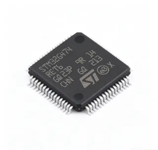
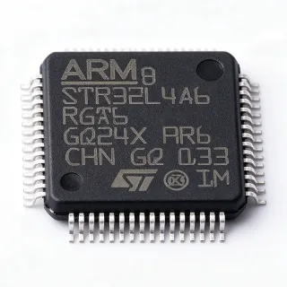
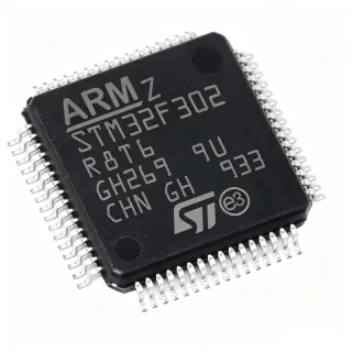
STM32G4A1RET6 - 170MHz Arm Cortex-M4F MCU | STMicroelectronics
MPN: STM32G4A1RET6 ✓ Active| Qty | Unit Price | Extended |
|---|---|---|
| 1 | $8.5 | $8.50 |
| 10 | $7.65 | $76.50 |
| 100 | $6.8 | $680.00 |
| 500 | $6.12 | $3,060.00 |
| 1,000 | $5.44 | $5,440.00 |
STM32G4A1RET6 Overview
A microcontroller (MCU) is a compact integrated circuit designed to govern a specific operation in an embedded system. It contains a processor core, memory, and programmable input/output peripherals on a single chip. The STM32G4A1RET6 belongs to the STM32G4 family, which is optimized for mixed-signal applications requiring high-resolution timers, fast ADCs, and advanced analog features. This MCU sits within the broader hierarchy of embedded processors, bridging general-purpose microcontrollers and digital signal processors (DSPs) with its FPU and DSP instructions.
Key features include a 170 MHz Arm Cortex-M4F core with DSP instructions and FPU, 512 KB of flash memory, and 96 KB of SRAM. It integrates a 12-bit ADC with hardware oversampling (up to 16-bit resolution), two 12-bit DACs, three fast comparators, and operational amplifiers. The device also includes advanced motor-control timers, a USB Type-C Power Delivery controller, and a CAN-FD interface. These features enable precise real-time control and efficient signal processing in demanding applications.
The STM32G4A1RET6 is built on a high-performance architecture with a nested vectored interrupt controller (NVIC) and a memory protection unit (MPU). It supports a wide supply voltage range of 1.71V to 3.6V and operates over a temperature range of -40°C to +85°C. The device includes multiple low-power modes, including Sleep, Stop, and Standby, to optimize energy consumption. Its advanced analog peripherals are designed to work seamlessly with the digital core, reducing external component count and system cost.
Typical applications include field-oriented control (FOC) of brushless DC motors, digital power supplies (e.g., LLC converters), solar inverters, and industrial sensors. The high-resolution timers (up to 184 ps resolution) and fast ADCs make it ideal for power conversion loops requiring high bandwidth. The USB Type-C PD controller simplifies implementation of power delivery in consumer and industrial devices.
When designing with this MCU, pay attention to the power supply decoupling: place a 100 nF capacitor close to each VDD pin and a 4.7 uF bulk capacitor. For analog performance, use a separate VDDA supply with a ferrite bead to isolate digital noise. The internal reference voltage (VREFINT) can be used for ADC calibration, but for higher accuracy, an external reference is recommended.
Drop-in alternatives for STM32G4A1RET6 — same package, pin-to-pin compatible. Different-package parts requiring PCB rework are excluded.
Variants in this series
Same-series models that are drop-in compatible with STM32G4A1RET6 (same form factor and footprint) — differing in Core, ADC Resolution, Communication Interfaces, Flash Memory, SRAM.
Quick Comparison Tool — Select alternative parts for side-by-side comparison:
STM32G4A1REI6
✅ Drop-In ⚠️ Specs Unverified📋 Reference alternative (not in catalog)
STM32G4A1REJ6
✅ Drop-In ⚠️ Specs Unverified📋 Reference alternative (not in catalog)
STM32G431RET6
⚡ Same Package ⚠️ Specs Unverified📋 Reference alternative (not in catalog)
STM32G474RET6
✅ Drop-In ⚠️ Specs Unverified✓ In Stock
$6.95 / Unit
View Datasheet →STM32G4A1RET6 Maximum Ratings & Electrical Characteristics
| Core | Arm Cortex-M4F with FPU |
| Maximum Clock Frequency | 170 MHz |
| Flash Memory | 512 KB |
| SRAM | 96 KB |
| Supply Voltage Range | 1.71 V to 3.6 V |
| Operating Temperature Range | -40C to +85C |
| Package | LQFP-64 (10x10 mm) |
| GPIO Pins | 51 |
| ADC Resolution | 12-bit (up to 16-bit with oversampling) |
| ADC Channels | 23 |
| DAC Resolution | 12-bit |
| DAC Channels | 2 |
| Timers | Advanced motor-control timers, high-resolution timers |
| Communication Interfaces | I2C, SPI, UART, CAN-FD, USB Type-C PD |
| DMA Channels | 16 |
| RoHS Status | Compliant |
STM32G4A1RET6 Pin Configuration
| Pin 1 | VBAT — Battery backup supply |
| Pin 2 | PC13 — GPIO / RTC |
| Pin 3 | PC14 — GPIO / OSC32_IN |
| Pin 4 | PC15 — GPIO / OSC32_OUT |
| Pin 5 | PF0 — GPIO |
| Pin 6 | PF1 — GPIO |
| Pin 7 | NRST — Reset |
| Pin 8 | VDD — Digital power supply |
| Pin 9 | VSS — Ground |
| Pin 10 | VDDA — Analog power supply |
| Pin 11 | PA0 — GPIO / ADC |
| Pin 12 | PA1 — GPIO / ADC |
| Pin 13 | PA2 — GPIO / USART |
| Pin 14 | PA3 — GPIO / USART |
| Pin 15 | PA4 — GPIO / DAC |
| Pin 16 | PA5 — GPIO / DAC |
| Pin 17 | PA6 — GPIO / TIM |
| Pin 18 | PA7 — GPIO / TIM |
| Pin 19 | PA8 — GPIO / USB |
| Pin 20 | PA9 — GPIO / USB |
| Pin 21 | PA10 — GPIO / USART |
| Pin 22 | PA11 — GPIO / USB |
| Pin 23 | PA12 — GPIO / USB |
| Pin 24 | PA13 — SWDIO |
| Pin 25 | PA14 — SWCLK |
| Pin 26 | PA15 — GPIO / JTDI |
| Pin 27 | PB0 — GPIO / ADC |
| Pin 28 | PB1 — GPIO / ADC |
| Pin 29 | PB2 — GPIO / BOOT1 |
| Pin 30 | PB3 — GPIO / JTDO |
| Pin 31 | PB4 — GPIO / NJTRST |
| Pin 32 | PB5 — GPIO / I2C |
| Pin 33 | PB6 — GPIO / I2C |
| Pin 34 | PB7 — GPIO / I2C |
| Pin 35 | PB8 — GPIO / CAN |
| Pin 36 | PB9 — GPIO / CAN |
| Pin 37 | PB10 — GPIO / SPI |
| Pin 38 | PB11 — GPIO / SPI |
| Pin 39 | PB12 — GPIO / SPI |
| Pin 40 | PB13 — GPIO / SPI |
| Pin 41 | PB14 — GPIO / TIM |
| Pin 42 | PB15 — GPIO / TIM |
| Pin 43 | PC0 — GPIO / ADC |
| Pin 44 | PC1 — GPIO / ADC |
| Pin 45 | PC2 — GPIO / ADC |
| Pin 46 | PC3 — GPIO / ADC |
| Pin 47 | PC4 — GPIO / ADC |
| Pin 48 | PC5 — GPIO / ADC |
| Pin 49 | PC6 — GPIO / TIM |
| Pin 50 | PC7 — GPIO / TIM |
| Pin 51 | PC8 — GPIO / TIM |
| Pin 52 | PC9 — GPIO / TIM |
| Pin 53 | PD0 — GPIO / OSC_IN |
| Pin 54 | PD1 — GPIO / OSC_OUT |
| Pin 55 | PD2 — GPIO |
| Pin 56 | PD3 — GPIO |
| Pin 57 | PD4 — GPIO |
| Pin 58 | PD5 — GPIO |
| Pin 59 | PD6 — GPIO |
| Pin 60 | PD7 — GPIO |
| Pin 61 | VDD — Digital power supply |
| Pin 62 | VSS — Ground |
| Pin 63 | PE0 — GPIO |
| Pin 64 | PE1 — GPIO |
Typical Applications
STM32G4A1RET6 is suitable for 6 applications: Field-Oriented Control (FOC) of Brushless DC Motors, Digital Power Supplies (LLC Converters), Solar Inverters, Industrial Sensors and Condition Monitoring, USB Type-C Power Delivery Adapters, Robotics and Drones.
Field-Oriented Control (FOC) of Brushless DC Motors
The STM32G4A1RET6 is ideal for FOC of BLDC motors due to its high-resolution timers (up to 184 ps) and fast 12-bit ADCs (up to 16-bit with oversampling). The advanced motor-control timers generate PWM signals with precise duty cycles, while the ADCs sample phase currents synchronously. The FPU accelerates the Clarke/Park transforms and PI controllers, enabling efficient, low-torque-ripple motor drives. In a typical application, the MCU reads current sensors via the ADC, computes the rotor position using Hall sensors or encoders, and updates PWM outputs at a 20 kHz loop rate. The integrated comparators provide overcurrent protection with minimal latency. Compared to general-purpose MCUs, the STM32G4A1RET6 reduces BOM cost by integrating analog peripherals and offers deterministic timing for high-bandwidth control loops.
Recommended
Digital Power Supplies (LLC Converters)
The STM32G4A1RET6 excels in digital power conversion, particularly LLC resonant converters. Its high-resolution timers generate PWM with up to 184 ps resolution, enabling precise frequency modulation for zero-voltage switching (ZVS). The fast ADCs sample output voltage and current at high rates, allowing the control loop to respond quickly to load transients. The FPU handles complex control algorithms, such as PID and state-space averaging, in real time. In a typical LLC converter, the MCU reads the output voltage via a resistor divider, compares it to a reference, and adjusts the switching frequency to maintain regulation. The integrated comparators can implement burst-mode protection. Compared to analog controllers, the STM32G4A1RET6 offers flexibility in firmware updates and advanced monitoring features, such as telemetry and fault logging.
Recommended
Solar Inverters
The STM32G4A1RET6 is well-suited for solar inverters, where it manages maximum power point tracking (MPPT) and grid synchronization. The high-resolution timers generate PWM for the DC-DC boost converter and the DC-AC inverter stage. The fast ADCs sample solar panel voltage and current to implement MPPT algorithms, such as perturb and observe. The FPU accelerates the computation of power and duty cycles. The CAN-FD interface allows communication with other system components, such as battery management systems. In a typical solar inverter, the MCU runs a control loop at 20 kHz, adjusting the duty cycle to extract maximum power from the panels. The integrated comparators provide overcurrent protection. Compared to other MCUs, the STM32G4A1RET6 offers a good balance of performance, analog integration, and cost for residential and commercial inverters.
Recommended
Industrial Sensors and Condition Monitoring
The STM32G4A1RET6 is used in industrial sensors for condition monitoring, such as vibration analysis and temperature sensing. Its 12-bit ADC with oversampling can achieve 16-bit resolution, enabling precise measurement of analog signals. The FPU processes FFT algorithms for vibration analysis, detecting anomalies in rotating machinery. The multiple communication interfaces (I2C, SPI, UART, CAN-FD) allow the sensor to interface with PLCs and industrial networks. In a typical application, the MCU samples an accelerometer via the ADC, performs FFT in real time, and transmits the spectrum over CAN-FD. The low-power modes extend battery life in wireless sensors. Compared to discrete solutions, the STM32G4A1RET6 integrates signal conditioning and processing, reducing board space and cost.
Recommended
USB Type-C Power Delivery Adapters
The STM32G4A1RET6 integrates a USB Type-C Power Delivery (PD) controller, making it ideal for USB-C adapters and chargers. The MCU handles the PD negotiation protocol, managing voltage and current requests from the sink device. The high-resolution timers can control the power stage for efficient conversion. The integrated DAC and comparators enable voltage and current monitoring. In a typical USB-C adapter, the MCU communicates with the sink over the CC lines, negotiates a power profile (e.g., 20V/5A), and adjusts the output accordingly. The USB PD controller simplifies the design by eliminating the need for an external PD chip. Compared to dedicated PD controllers, the STM32G4A1RET6 offers flexibility for custom power profiles and additional features like telemetry.
Recommended
Robotics and Drones
The STM32G4A1RET6 is used in robotics and drones for motor control, sensor fusion, and flight control. Its high-resolution timers drive brushless motors with precise speed control, while the FPU processes sensor data from IMUs and encoders. The multiple communication interfaces allow connection to GPS modules, radio transceivers, and other peripherals. In a typical drone, the MCU runs a control loop at 1 kHz, reading gyroscope and accelerometer data, computing attitude, and adjusting motor speeds. The low-power modes extend flight time. Compared to other MCUs, the STM32G4A1RET6 offers a good balance of performance, analog integration, and size, making it suitable for compact designs.
Recommended
Recommended Products Summary
Engineering reference data for STM32G4A1RET6 — comparison, design guidance, and compliance information.
Selection Guide
Comparison with Alternatives
| Parameter | This Product | STM32G4A1REI6 | STM32G4A1REJ6 | STM32G431RET6 | STM32G474RET6 |
|---|---|---|---|---|---|
| Package | LQFP-64 | UFBGA-64 | LQFP-64 | LQFP-64 | LQFP-64 |
| Brand | STMicroelectronics | STMicroelectronics | STMicroelectronics | STMicroelectronics | STMicroelectronics |
| Core | Cortex-M4F @ 170 MHz | Cortex-M4F @ 170 MHz | Cortex-M4F @ 170 MHz | Cortex-M4F @ 170 MHz | Cortex-M4F @ 170 MHz |
| Flash Memory | 512 KB | 512 KB | 512 KB | 128 KB | 512 KB |
| SRAM | 96 KB | 96 KB | 96 KB | 32 KB | 128 KB |
| USB Type-C PD | Yes | Yes | Yes | No | No |
| Number of Comparators | 3 | 3 | 3 | 3 | 6 |
| Operating Temperature Range | -40C to +85C | -40C to +85C | -40C to +125C | -40C to +85C | -40C to +85C |
Key Differentiators
- Integrated USB Type-C Power Delivery controller (vs STM32G431RET6)
- 512 KB flash memory (vs STM32G431RET6)
- High-resolution timers with 184 ps resolution (vs STM32G474RET6)
Design Notes
Decouple each VDD pin with a 100 nF ceramic capacitor placed as close as possible to the pin. Add a 4.7 uF bulk capacitor on the main supply. For VDDA, use a ferrite bead in series with the analog supply and a 1 uF capacitor to ground to reduce digital noise coupling into the ADC.
For the LQFP-64 package, ensure a solid ground plane under the MCU. Route high-speed signals (e.g., SPI, USB) with controlled impedance if needed. Keep analog traces short and away from digital switching signals. Use separate analog and digital ground planes connected at a single point.
Do not exceed the absolute maximum ratings: VDD max 3.6V, and any pin voltage must be within -0.3V to VDD+0.3V. Ensure the BOOT0 pin is properly configured to avoid accidental boot from system memory. For ADC accuracy, use an external voltage reference if the internal VREFINT is not sufficient.
Compliance Information
RoHS and REACH compliant per STMicroelectronics. Not AEC-Q100 qualified; for automotive, consider STM32G4A1REJ6 with extended temperature range.